
1.2: Book Outline
- Page ID
- 41000

\( \newcommand{\vecs}[1]{\overset { \scriptstyle \rightharpoonup} {\mathbf{#1}} } \)
\( \newcommand{\vecd}[1]{\overset{-\!-\!\rightharpoonup}{\vphantom{a}\smash {#1}}} \)
\( \newcommand{\id}{\mathrm{id}}\) \( \newcommand{\Span}{\mathrm{span}}\)
( \newcommand{\kernel}{\mathrm{null}\,}\) \( \newcommand{\range}{\mathrm{range}\,}\)
\( \newcommand{\RealPart}{\mathrm{Re}}\) \( \newcommand{\ImaginaryPart}{\mathrm{Im}}\)
\( \newcommand{\Argument}{\mathrm{Arg}}\) \( \newcommand{\norm}[1]{\| #1 \|}\)
\( \newcommand{\inner}[2]{\langle #1, #2 \rangle}\)
\( \newcommand{\Span}{\mathrm{span}}\)
\( \newcommand{\id}{\mathrm{id}}\)
\( \newcommand{\Span}{\mathrm{span}}\)
\( \newcommand{\kernel}{\mathrm{null}\,}\)
\( \newcommand{\range}{\mathrm{range}\,}\)
\( \newcommand{\RealPart}{\mathrm{Re}}\)
\( \newcommand{\ImaginaryPart}{\mathrm{Im}}\)
\( \newcommand{\Argument}{\mathrm{Arg}}\)
\( \newcommand{\norm}[1]{\| #1 \|}\)
\( \newcommand{\inner}[2]{\langle #1, #2 \rangle}\)
\( \newcommand{\Span}{\mathrm{span}}\) \( \newcommand{\AA}{\unicode[.8,0]{x212B}}\)
\( \newcommand{\vectorA}[1]{\vec{#1}} % arrow\)
\( \newcommand{\vectorAt}[1]{\vec{\text{#1}}} % arrow\)
\( \newcommand{\vectorB}[1]{\overset { \scriptstyle \rightharpoonup} {\mathbf{#1}} } \)
\( \newcommand{\vectorC}[1]{\textbf{#1}} \)
\( \newcommand{\vectorD}[1]{\overrightarrow{#1}} \)
\( \newcommand{\vectorDt}[1]{\overrightarrow{\text{#1}}} \)
\( \newcommand{\vectE}[1]{\overset{-\!-\!\rightharpoonup}{\vphantom{a}\smash{\mathbf {#1}}}} \)
\( \newcommand{\vecs}[1]{\overset { \scriptstyle \rightharpoonup} {\mathbf{#1}} } \)
\( \newcommand{\vecd}[1]{\overset{-\!-\!\rightharpoonup}{\vphantom{a}\smash {#1}}} \)
\(\newcommand{\avec}{\mathbf a}\) \(\newcommand{\bvec}{\mathbf b}\) \(\newcommand{\cvec}{\mathbf c}\) \(\newcommand{\dvec}{\mathbf d}\) \(\newcommand{\dtil}{\widetilde{\mathbf d}}\) \(\newcommand{\evec}{\mathbf e}\) \(\newcommand{\fvec}{\mathbf f}\) \(\newcommand{\nvec}{\mathbf n}\) \(\newcommand{\pvec}{\mathbf p}\) \(\newcommand{\qvec}{\mathbf q}\) \(\newcommand{\svec}{\mathbf s}\) \(\newcommand{\tvec}{\mathbf t}\) \(\newcommand{\uvec}{\mathbf u}\) \(\newcommand{\vvec}{\mathbf v}\) \(\newcommand{\wvec}{\mathbf w}\) \(\newcommand{\xvec}{\mathbf x}\) \(\newcommand{\yvec}{\mathbf y}\) \(\newcommand{\zvec}{\mathbf z}\) \(\newcommand{\rvec}{\mathbf r}\) \(\newcommand{\mvec}{\mathbf m}\) \(\newcommand{\zerovec}{\mathbf 0}\) \(\newcommand{\onevec}{\mathbf 1}\) \(\newcommand{\real}{\mathbb R}\) \(\newcommand{\twovec}[2]{\left[\begin{array}{r}#1 \\ #2 \end{array}\right]}\) \(\newcommand{\ctwovec}[2]{\left[\begin{array}{c}#1 \\ #2 \end{array}\right]}\) \(\newcommand{\threevec}[3]{\left[\begin{array}{r}#1 \\ #2 \\ #3 \end{array}\right]}\) \(\newcommand{\cthreevec}[3]{\left[\begin{array}{c}#1 \\ #2 \\ #3 \end{array}\right]}\) \(\newcommand{\fourvec}[4]{\left[\begin{array}{r}#1 \\ #2 \\ #3 \\ #4 \end{array}\right]}\) \(\newcommand{\cfourvec}[4]{\left[\begin{array}{c}#1 \\ #2 \\ #3 \\ #4 \end{array}\right]}\) \(\newcommand{\fivevec}[5]{\left[\begin{array}{r}#1 \\ #2 \\ #3 \\ #4 \\ #5 \\ \end{array}\right]}\) \(\newcommand{\cfivevec}[5]{\left[\begin{array}{c}#1 \\ #2 \\ #3 \\ #4 \\ #5 \\ \end{array}\right]}\) \(\newcommand{\mattwo}[4]{\left[\begin{array}{rr}#1 \amp #2 \\ #3 \amp #4 \\ \end{array}\right]}\) \(\newcommand{\laspan}[1]{\text{Span}\{#1\}}\) \(\newcommand{\bcal}{\cal B}\) \(\newcommand{\ccal}{\cal C}\) \(\newcommand{\scal}{\cal S}\) \(\newcommand{\wcal}{\cal W}\) \(\newcommand{\ecal}{\cal E}\) \(\newcommand{\coords}[2]{\left\{#1\right\}_{#2}}\) \(\newcommand{\gray}[1]{\color{gray}{#1}}\) \(\newcommand{\lgray}[1]{\color{lightgray}{#1}}\) \(\newcommand{\rank}{\operatorname{rank}}\) \(\newcommand{\row}{\text{Row}}\) \(\newcommand{\col}{\text{Col}}\) \(\renewcommand{\row}{\text{Row}}\) \(\newcommand{\nul}{\text{Nul}}\) \(\newcommand{\var}{\text{Var}}\) \(\newcommand{\corr}{\text{corr}}\) \(\newcommand{\len}[1]{\left|#1\right|}\) \(\newcommand{\bbar}{\overline{\bvec}}\) \(\newcommand{\bhat}{\widehat{\bvec}}\) \(\newcommand{\bperp}{\bvec^\perp}\) \(\newcommand{\xhat}{\widehat{\xvec}}\) \(\newcommand{\vhat}{\widehat{\vvec}}\) \(\newcommand{\uhat}{\widehat{\uvec}}\) \(\newcommand{\what}{\widehat{\wvec}}\) \(\newcommand{\Sighat}{\widehat{\Sigma}}\) \(\newcommand{\lt}{<}\) \(\newcommand{\gt}{>}\) \(\newcommand{\amp}{&}\) \(\definecolor{fillinmathshade}{gray}{0.9}\)The telegraphist’s equations, used to analyze transmission lines, and their interpretations are presented in Chapter 2 where transmission line theory is presented. This leads to the analysis of terminated transmission lines with key results being how these can be used as circuit elements to realize narrow-band inductors and capacitors. The chapter concludes by developing circuit models of transmission lines that are suitable for use in circuit simulators and in designing circuits using transmission lines.
Chapters 2–6 describe transmission lines and the exploitation of transmission effects that are used in RF and microwave engineering. One of the aspects that distinguishes design at a few tens of megahertz and below from design above a few megahertz up to a terahertz is that at low frequencies design proceeds with the assumption that circuit elements and indeed whole circuits exist at a point and there is no time-of-flight, e.g. speed-of-light, limitation to a voltage and current at one point in a circuit instantaneously impacting the voltage and current anywhere else in the circuit. As the frequency of operation of a circuit increases, the effect of the finite speed of light becomes significant and distributed effects often need to be considered.
Chapter 3 focuses on a class of transmission lines called planar lines which are lines usually fabricated starting with a low loss dielectric substrate with metal sheets on both sides. The most important planar transmission line is the microstrip line shown in Figure \(\PageIndex{1}\). This is the most widely used
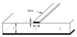
Figure \(\PageIndex{1}\): Microstrip transmission line.
interconnect at microwave frequencies. The strip of the line is formed by patterning the top conductor and etching away the unwanted metal. The defining distinction between a microstrip line, and any planar transmission line, and a trace on a printed circuit board is that at microwave frequencies attention must be given to providing a signal return path and maintaining as uniform an environment as possible for the electric and magnetic fields. Any discontinuity will introduce reflections of EM energy. This may actually be desired when implementing circuit elements but if not it is important that geometrical uniformity be maintained. Considering the microstrip line, see Figure \(\PageIndex{1}\), the width, \(w\), of the strip and the thickness, \(h\), of the substrate define the ratio of the voltage and current signals traveling along the microstrip line. This ratio is called the characteristic impedance of the line and it is critical for reliable signal transmission, i.e., good signal integrity, that the cross-sectional geometry be the same along the line as then the characteristic impedance of the line is constant.
While simple in concept, planar transmission lines needed to be invented. As well as conceptualizing a transmission line that can be realized by etching a planar metallic conductor on the printed circuit board, it is essential to provide the analytic tools that enable the propagation characteristics of the line to be calculated and enable structures such as couplers and filters to be synthesized using planar transmission lines. The origins of microstrip trace back to developments in the early 1940s, beginning with a coaxial line with a flat center conductor forming a rectangular coaxial line [5]. At that time printed circuit boards were being used for low-frequency circuits. In 1949 these came together when Barrett reasoned that the thick center conductor of the rectangular coaxial transmission line could be very thin with little effect on the properties of the line. This then meant that low-frequency printed circuit board techniques could be employed in microwave circuits and the transmission line system became known as stripline [5, 6].
The conceptual evolution of stripline is shown in Figure \(\PageIndex{2}\). The stripline configuration is developed by sandwiching a metallic strip between two metal-clad dielectric sheets. As initially envisioned, the strip could be stamped out or silk-screened using silver ink. Today it is most common to begin with a continuous metallic sheet bonded to one or both sides of a dielectric sheet. A pattern of an etch resistant material is then photolithographically defined on the sheet and the strip pattern appears after etching. The next advance in 1952 when Grieg and Engelmann removed one of stripline’s ground planes thus becoming microstrip [7]. With an invention it is not sufficient to simply describe a structure, in this case understanding had to be provided as evidenced by presenting design equations for the electrical properties of the line. The essential electrical properties of a transmission line are its characteristic impedance, the ratio of the traveling voltage and current waves on the line, and its propagation constant, which relates to the speed of propagation of the voltage and current
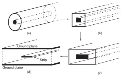
Figure \(\PageIndex{2}\): Evolution of the stripline transmission line: (a) coaxial line with a round center conductor; (b) square coaxial line with a square flat center conductor; (c) rectangular coaxial line with a flat center conductor; and (d) stripline.
waves on the lines.
Planar lines are not ideal transmission lines and undesired effects must be anticipated and design adjusted to reduce their occurrence or impact. These extraordinary effects are considered in Chapter 4. Understanding and anticipating these effects is really where the art of microwave design comes into play. Many of the effects occur when dimensions are too large but at the same time manufacturability improves when dimensions are large, so a design trade-off is required. Rarely is a design successful on the first pass. Thus it is important for a microwave engineer to interpret undesirable results and know what to modify in a design. It is difficult to do measurements at microwave frequencies as anything that is introduced in a measurement, e.g. a probe, will have significant impact on a circuit. Often a few indirect measurements, some analysis, and great intuition is required to correctly identify and hence resolve design issues.
Chapter 4 begins by considering frequency-dependent characteristics of planar lines and then moves on to developing analysis equations and design concepts for microstrip lines at high frequencies. As the transverse dimensions of a planar line approach a wavelength, say greater than a tenth of a wavelength, it is possible for the EM signal to travel down the line in two (or more field) orientations called modes and these travel at different velocities and corrupt a signal. Multimoding is nearly always undesirable so understanding the origins of multiple modes and designing to avoid multiple modes is an important consideration. However in some situations these modes is exploited, e.g. in realizing a small area inductor on an RFIC.
When two planar lines are close to each other the fields of one line can be in the vicinity of the other line and the lines are coupled. A portion of the energy of a signal traveling on one of the lines can appear on the other line. Many circuit elements can be developed by exploiting parallel coupled lines (PCLs). Chapter 5 begins by presenting the physics of coupling and then a generalization of the telegraphist’s equations for coupled transmission lines. Design approaches and circuit models are developed and the circuit models enable the synthesis of microwave designs using parallel coupled lines Several PCL circuit elements are presented but many more will be described in other volumes of this book series.
The final chapter of this volume, Chapter 6, discusses rectangular waveguides. Instead of ‘rectangular waveguide’ just the term ‘waveguide’ is usually used with the understanding that reference is being made to a rectangular waveguide. This is a little confusing because really all transmission lines guide waves and so are waveguides. A rectangular waveguide is a very different type of transmission line that confines the EM fields inside a rectangular metal pipe. These are important elements starting at low microwave frequencies, \(1\text{ GHz}\) and above, as they can carry very powerful signals with very little loss. They are almost always used in radar and similar high power applications. Waveguides are also very important at higher frequencies even when power levels are relatively low. They are often used at \(15\text{ GHz}\) and above as they have very little loss while the loss of coaxial lines grows tremendously with frequency. With waveguides it is very difficult to use voltage and current concepts except over very narrow fractional bandwidths, a few percent at most. This means that it is very difficult to do circuit design using waveguides.