
6.6: Phase Detector
- Page ID
- 46144
\( \newcommand{\vecs}[1]{\overset { \scriptstyle \rightharpoonup} {\mathbf{#1}} } \)
\( \newcommand{\vecd}[1]{\overset{-\!-\!\rightharpoonup}{\vphantom{a}\smash {#1}}} \)
\( \newcommand{\id}{\mathrm{id}}\) \( \newcommand{\Span}{\mathrm{span}}\)
( \newcommand{\kernel}{\mathrm{null}\,}\) \( \newcommand{\range}{\mathrm{range}\,}\)
\( \newcommand{\RealPart}{\mathrm{Re}}\) \( \newcommand{\ImaginaryPart}{\mathrm{Im}}\)
\( \newcommand{\Argument}{\mathrm{Arg}}\) \( \newcommand{\norm}[1]{\| #1 \|}\)
\( \newcommand{\inner}[2]{\langle #1, #2 \rangle}\)
\( \newcommand{\Span}{\mathrm{span}}\)
\( \newcommand{\id}{\mathrm{id}}\)
\( \newcommand{\Span}{\mathrm{span}}\)
\( \newcommand{\kernel}{\mathrm{null}\,}\)
\( \newcommand{\range}{\mathrm{range}\,}\)
\( \newcommand{\RealPart}{\mathrm{Re}}\)
\( \newcommand{\ImaginaryPart}{\mathrm{Im}}\)
\( \newcommand{\Argument}{\mathrm{Arg}}\)
\( \newcommand{\norm}[1]{\| #1 \|}\)
\( \newcommand{\inner}[2]{\langle #1, #2 \rangle}\)
\( \newcommand{\Span}{\mathrm{span}}\) \( \newcommand{\AA}{\unicode[.8,0]{x212B}}\)
\( \newcommand{\vectorA}[1]{\vec{#1}} % arrow\)
\( \newcommand{\vectorAt}[1]{\vec{\text{#1}}} % arrow\)
\( \newcommand{\vectorB}[1]{\overset { \scriptstyle \rightharpoonup} {\mathbf{#1}} } \)
\( \newcommand{\vectorC}[1]{\textbf{#1}} \)
\( \newcommand{\vectorD}[1]{\overrightarrow{#1}} \)
\( \newcommand{\vectorDt}[1]{\overrightarrow{\text{#1}}} \)
\( \newcommand{\vectE}[1]{\overset{-\!-\!\rightharpoonup}{\vphantom{a}\smash{\mathbf {#1}}}} \)
\( \newcommand{\vecs}[1]{\overset { \scriptstyle \rightharpoonup} {\mathbf{#1}} } \)
\( \newcommand{\vecd}[1]{\overset{-\!-\!\rightharpoonup}{\vphantom{a}\smash {#1}}} \)
\(\newcommand{\avec}{\mathbf a}\) \(\newcommand{\bvec}{\mathbf b}\) \(\newcommand{\cvec}{\mathbf c}\) \(\newcommand{\dvec}{\mathbf d}\) \(\newcommand{\dtil}{\widetilde{\mathbf d}}\) \(\newcommand{\evec}{\mathbf e}\) \(\newcommand{\fvec}{\mathbf f}\) \(\newcommand{\nvec}{\mathbf n}\) \(\newcommand{\pvec}{\mathbf p}\) \(\newcommand{\qvec}{\mathbf q}\) \(\newcommand{\svec}{\mathbf s}\) \(\newcommand{\tvec}{\mathbf t}\) \(\newcommand{\uvec}{\mathbf u}\) \(\newcommand{\vvec}{\mathbf v}\) \(\newcommand{\wvec}{\mathbf w}\) \(\newcommand{\xvec}{\mathbf x}\) \(\newcommand{\yvec}{\mathbf y}\) \(\newcommand{\zvec}{\mathbf z}\) \(\newcommand{\rvec}{\mathbf r}\) \(\newcommand{\mvec}{\mathbf m}\) \(\newcommand{\zerovec}{\mathbf 0}\) \(\newcommand{\onevec}{\mathbf 1}\) \(\newcommand{\real}{\mathbb R}\) \(\newcommand{\twovec}[2]{\left[\begin{array}{r}#1 \\ #2 \end{array}\right]}\) \(\newcommand{\ctwovec}[2]{\left[\begin{array}{c}#1 \\ #2 \end{array}\right]}\) \(\newcommand{\threevec}[3]{\left[\begin{array}{r}#1 \\ #2 \\ #3 \end{array}\right]}\) \(\newcommand{\cthreevec}[3]{\left[\begin{array}{c}#1 \\ #2 \\ #3 \end{array}\right]}\) \(\newcommand{\fourvec}[4]{\left[\begin{array}{r}#1 \\ #2 \\ #3 \\ #4 \end{array}\right]}\) \(\newcommand{\cfourvec}[4]{\left[\begin{array}{c}#1 \\ #2 \\ #3 \\ #4 \end{array}\right]}\) \(\newcommand{\fivevec}[5]{\left[\begin{array}{r}#1 \\ #2 \\ #3 \\ #4 \\ #5 \\ \end{array}\right]}\) \(\newcommand{\cfivevec}[5]{\left[\begin{array}{c}#1 \\ #2 \\ #3 \\ #4 \\ #5 \\ \end{array}\right]}\) \(\newcommand{\mattwo}[4]{\left[\begin{array}{rr}#1 \amp #2 \\ #3 \amp #4 \\ \end{array}\right]}\) \(\newcommand{\laspan}[1]{\text{Span}\{#1\}}\) \(\newcommand{\bcal}{\cal B}\) \(\newcommand{\ccal}{\cal C}\) \(\newcommand{\scal}{\cal S}\) \(\newcommand{\wcal}{\cal W}\) \(\newcommand{\ecal}{\cal E}\) \(\newcommand{\coords}[2]{\left\{#1\right\}_{#2}}\) \(\newcommand{\gray}[1]{\color{gray}{#1}}\) \(\newcommand{\lgray}[1]{\color{lightgray}{#1}}\) \(\newcommand{\rank}{\operatorname{rank}}\) \(\newcommand{\row}{\text{Row}}\) \(\newcommand{\col}{\text{Col}}\) \(\renewcommand{\row}{\text{Row}}\) \(\newcommand{\nul}{\text{Nul}}\) \(\newcommand{\var}{\text{Var}}\) \(\newcommand{\corr}{\text{corr}}\) \(\newcommand{\len}[1]{\left|#1\right|}\) \(\newcommand{\bbar}{\overline{\bvec}}\) \(\newcommand{\bhat}{\widehat{\bvec}}\) \(\newcommand{\bperp}{\bvec^\perp}\) \(\newcommand{\xhat}{\widehat{\xvec}}\) \(\newcommand{\vhat}{\widehat{\vvec}}\) \(\newcommand{\uhat}{\widehat{\uvec}}\) \(\newcommand{\what}{\widehat{\wvec}}\) \(\newcommand{\Sighat}{\widehat{\Sigma}}\) \(\newcommand{\lt}{<}\) \(\newcommand{\gt}{>}\) \(\newcommand{\amp}{&}\) \(\definecolor{fillinmathshade}{gray}{0.9}\)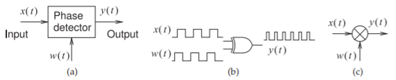
Figure \(\PageIndex{1}\): A phase detector: (a) block diagram; (b) a digital phase detector using an XOR gate; and (c) analog phase detector using a multiplier and filtering (not shown).
A phase detector, also called a phase comparator, compares two waveforms and the output of the phase detector is a representation of the phase difference of the signals. There are two basic types of phase detectors: sinusoidal phase detectors and square signal phase detectors, which operate either in binary mode or by detecting zero crossings. The block diagram of a phase detector is shown in Figure \(\PageIndex{1}\)(a) with the output \(y(t)\) related to the difference of the phase of the input signals \(x(t)\) and \(w(t)\).
A square wave detector is based on a logic circuit producing a signal that is averaged (or integrated) over time. An example is the XOR gate shown in Figure \(\PageIndex{1}\)(b), which compares two digital signals that here have the same frequency but are shifted in phase. The output of the XOR gate, \(y(t)\), is also a pulse train, and the average value of \(y(t)\) is proportional to the phase difference of \(x(t)\) and \(w(t)\). This average value can be obtained by passing \(y(t)\) through a lowpass filter to obtain a DC value. If \(x(t)\) and \(w(t)\) have different but close frequencies, the output of the lowpass filter will be a slowly varying signal. This circuit could be used to detect the phase difference of analog signals, but the signals first need to be converted to digital signals. This can be obtained through saturating amplification of the signals or by circuitry that responds to zero-crossings and produces a binary signal. Other digital phase comparators can be realized using charge-pumps, flip-flops, and sample-and-hold circuits.
Sinusoidal phase detectors can use a mixer or an analog multiplier, as shown in Figure \(\PageIndex{1}\)(c). The inputs could be two sinusoids with one of them adjusted in phase either externally or within the detector itself. So consider the inputs to the phase detector to be
\[\label{eq:1}x(t)=A_{x}\sin(\omega_{x}t+\phi_{x})\quad\text{and}\quad w(t)=A_{w}\cos(\omega_{w}t+\phi_{w}) \]
Then the output of the multiplier is
\[\begin{align}y(t)&=A_{x}\sin(\omega_{x}t+\phi_{x})A_{w}\cos(\omega_{w}t+\phi_{w})\nonumber \\ \label{eq:2}&=\frac{1}{2}A_{x}A_{w}[\sin(\omega_{x}t+\omega_{w}t+\phi_{x}+\phi_{w})+\sin(\omega_{x}t-\omega_{w}t+\phi_{x}-\phi_{w})]\end{align} \]
Typically the frequencies of the two input signals are close so that \(\omega_{x} = \omega +\frac{1}{2}\Delta\omega\) and \(\omega_{w} =\omega −\frac{1}{2}\Delta\omega\), where \(\Delta\omega\) is small and in most phase detector applications either \(\Delta\omega = 0\) or a feedback loop attempts to set \(\Delta\omega\) to zero so there is little frequency error. So, following lowpass filtering, the output of
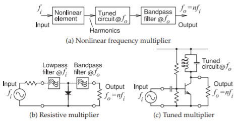
Figure \(\PageIndex{2}\): Frequency multipliers.
the phase detector is
\[\label{eq:3}y(t)=\frac{1}{2}A_{x}A_{w}\sin(\Delta\omega t+\phi_{x}-\phi_{w}) \]
Now \(\Delta\omega t\) can be considered to be a phase error and incorporated in effective phases of the input signals, \(\psi_{x}(t) = \frac{1}{2}\Delta\omega t+\phi_{x}\) and \(\psi_{w}(t) = −\frac{1}{2}\Delta\omega t + \phi_{w}\). Then
\[\label{eq:4}y(t)=\frac{1}{2}A_{x}A_{w}\sin[\psi_{x}(t)-\psi_{w}(t)] \]
This is a functional phase detector provided that the difference in the phases of the input signals is between \(−\pi /2\) and \(\pi /2\).
A variation of the sinusoidal detector is called a phase-frequency detector (PFD) which has an extended range and the effective phase difference of the input signals can have a magnitude greater than \(\pi /2\) [31, 32].
The output signal, \(y(t)\), is proportional to the amplitudes of the input signals and to their phase difference. In practice the amplitudes of both input signals are scaled to a constant amplitude so that the output only depends on the phase difference.
When a mixer is used in a phase detector, it operates much the same way as a multiplier. With a switching mixer one of the input signals becomes the drive of the switching part of the mixer and the other signal is the sinusoidal drive. Now only the second input need be scaled to have a constant amplitude.