
11.5: Filter Class or Alignment
- Page ID
- 3618

\( \newcommand{\vecs}[1]{\overset { \scriptstyle \rightharpoonup} {\mathbf{#1}} } \)
\( \newcommand{\vecd}[1]{\overset{-\!-\!\rightharpoonup}{\vphantom{a}\smash {#1}}} \)
\( \newcommand{\dsum}{\displaystyle\sum\limits} \)
\( \newcommand{\dint}{\displaystyle\int\limits} \)
\( \newcommand{\dlim}{\displaystyle\lim\limits} \)
\( \newcommand{\id}{\mathrm{id}}\) \( \newcommand{\Span}{\mathrm{span}}\)
( \newcommand{\kernel}{\mathrm{null}\,}\) \( \newcommand{\range}{\mathrm{range}\,}\)
\( \newcommand{\RealPart}{\mathrm{Re}}\) \( \newcommand{\ImaginaryPart}{\mathrm{Im}}\)
\( \newcommand{\Argument}{\mathrm{Arg}}\) \( \newcommand{\norm}[1]{\| #1 \|}\)
\( \newcommand{\inner}[2]{\langle #1, #2 \rangle}\)
\( \newcommand{\Span}{\mathrm{span}}\)
\( \newcommand{\id}{\mathrm{id}}\)
\( \newcommand{\Span}{\mathrm{span}}\)
\( \newcommand{\kernel}{\mathrm{null}\,}\)
\( \newcommand{\range}{\mathrm{range}\,}\)
\( \newcommand{\RealPart}{\mathrm{Re}}\)
\( \newcommand{\ImaginaryPart}{\mathrm{Im}}\)
\( \newcommand{\Argument}{\mathrm{Arg}}\)
\( \newcommand{\norm}[1]{\| #1 \|}\)
\( \newcommand{\inner}[2]{\langle #1, #2 \rangle}\)
\( \newcommand{\Span}{\mathrm{span}}\) \( \newcommand{\AA}{\unicode[.8,0]{x212B}}\)
\( \newcommand{\vectorA}[1]{\vec{#1}} % arrow\)
\( \newcommand{\vectorAt}[1]{\vec{\text{#1}}} % arrow\)
\( \newcommand{\vectorB}[1]{\overset { \scriptstyle \rightharpoonup} {\mathbf{#1}} } \)
\( \newcommand{\vectorC}[1]{\textbf{#1}} \)
\( \newcommand{\vectorD}[1]{\overrightarrow{#1}} \)
\( \newcommand{\vectorDt}[1]{\overrightarrow{\text{#1}}} \)
\( \newcommand{\vectE}[1]{\overset{-\!-\!\rightharpoonup}{\vphantom{a}\smash{\mathbf {#1}}}} \)
\( \newcommand{\vecs}[1]{\overset { \scriptstyle \rightharpoonup} {\mathbf{#1}} } \)
\(\newcommand{\longvect}{\overrightarrow}\)
\( \newcommand{\vecd}[1]{\overset{-\!-\!\rightharpoonup}{\vphantom{a}\smash {#1}}} \)
\(\newcommand{\avec}{\mathbf a}\) \(\newcommand{\bvec}{\mathbf b}\) \(\newcommand{\cvec}{\mathbf c}\) \(\newcommand{\dvec}{\mathbf d}\) \(\newcommand{\dtil}{\widetilde{\mathbf d}}\) \(\newcommand{\evec}{\mathbf e}\) \(\newcommand{\fvec}{\mathbf f}\) \(\newcommand{\nvec}{\mathbf n}\) \(\newcommand{\pvec}{\mathbf p}\) \(\newcommand{\qvec}{\mathbf q}\) \(\newcommand{\svec}{\mathbf s}\) \(\newcommand{\tvec}{\mathbf t}\) \(\newcommand{\uvec}{\mathbf u}\) \(\newcommand{\vvec}{\mathbf v}\) \(\newcommand{\wvec}{\mathbf w}\) \(\newcommand{\xvec}{\mathbf x}\) \(\newcommand{\yvec}{\mathbf y}\) \(\newcommand{\zvec}{\mathbf z}\) \(\newcommand{\rvec}{\mathbf r}\) \(\newcommand{\mvec}{\mathbf m}\) \(\newcommand{\zerovec}{\mathbf 0}\) \(\newcommand{\onevec}{\mathbf 1}\) \(\newcommand{\real}{\mathbb R}\) \(\newcommand{\twovec}[2]{\left[\begin{array}{r}#1 \\ #2 \end{array}\right]}\) \(\newcommand{\ctwovec}[2]{\left[\begin{array}{c}#1 \\ #2 \end{array}\right]}\) \(\newcommand{\threevec}[3]{\left[\begin{array}{r}#1 \\ #2 \\ #3 \end{array}\right]}\) \(\newcommand{\cthreevec}[3]{\left[\begin{array}{c}#1 \\ #2 \\ #3 \end{array}\right]}\) \(\newcommand{\fourvec}[4]{\left[\begin{array}{r}#1 \\ #2 \\ #3 \\ #4 \end{array}\right]}\) \(\newcommand{\cfourvec}[4]{\left[\begin{array}{c}#1 \\ #2 \\ #3 \\ #4 \end{array}\right]}\) \(\newcommand{\fivevec}[5]{\left[\begin{array}{r}#1 \\ #2 \\ #3 \\ #4 \\ #5 \\ \end{array}\right]}\) \(\newcommand{\cfivevec}[5]{\left[\begin{array}{c}#1 \\ #2 \\ #3 \\ #4 \\ #5 \\ \end{array}\right]}\) \(\newcommand{\mattwo}[4]{\left[\begin{array}{rr}#1 \amp #2 \\ #3 \amp #4 \\ \end{array}\right]}\) \(\newcommand{\laspan}[1]{\text{Span}\{#1\}}\) \(\newcommand{\bcal}{\cal B}\) \(\newcommand{\ccal}{\cal C}\) \(\newcommand{\scal}{\cal S}\) \(\newcommand{\wcal}{\cal W}\) \(\newcommand{\ecal}{\cal E}\) \(\newcommand{\coords}[2]{\left\{#1\right\}_{#2}}\) \(\newcommand{\gray}[1]{\color{gray}{#1}}\) \(\newcommand{\lgray}[1]{\color{lightgray}{#1}}\) \(\newcommand{\rank}{\operatorname{rank}}\) \(\newcommand{\row}{\text{Row}}\) \(\newcommand{\col}{\text{Col}}\) \(\renewcommand{\row}{\text{Row}}\) \(\newcommand{\nul}{\text{Nul}}\) \(\newcommand{\var}{\text{Var}}\) \(\newcommand{\corr}{\text{corr}}\) \(\newcommand{\len}[1]{\left|#1\right|}\) \(\newcommand{\bbar}{\overline{\bvec}}\) \(\newcommand{\bhat}{\widehat{\bvec}}\) \(\newcommand{\bperp}{\bvec^\perp}\) \(\newcommand{\xhat}{\widehat{\xvec}}\) \(\newcommand{\vhat}{\widehat{\vvec}}\) \(\newcommand{\uhat}{\widehat{\uvec}}\) \(\newcommand{\what}{\widehat{\wvec}}\) \(\newcommand{\Sighat}{\widehat{\Sigma}}\) \(\newcommand{\lt}{<}\) \(\newcommand{\gt}{>}\) \(\newcommand{\amp}{&}\) \(\definecolor{fillinmathshade}{gray}{0.9}\)Besides order, the shape of the transition band is determined by a filter's class, or alignment. These terms are synonymous and reflect the filter's damping factor. Damping factor is the reciprocal of \(Q\), the quality factor. You should be familiar with \(Q\) from earlier work with inductors and resonant circuits. The symbol for damping factor is alpha, \(\alpha\). Alignment plays a key role in determining the shape of the transition region and, in some cases, the pass-band or stop-band shape also. There are a great number of possible filter alignments. We will look at a few of the more popular types. A graph comparing the relative responses of the major types is shown in Figure \(\PageIndex{1}\). For simplicity, only second-order types are shown. Figure \(\PageIndex{1a}\) shows filters with the same critical frequency and identical DC gains. In Figure \(\PageIndex{1b}\) the responses have been adjusted for a peak gain of 0 dB and identical break frequencies \((f_{3dB})\).
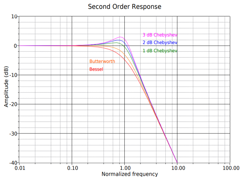
Figure \(\PageIndex{1a}\): A comparison of the major filter alignments: second order response.
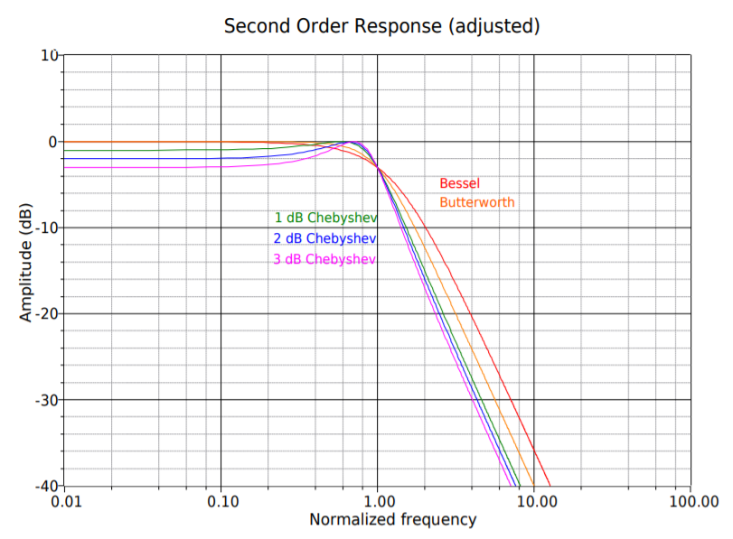
Figure \(\PageIndex{1b}\): A comparison of the major filter alignments: second order response (adjusted).
11.5.1: Butterworth
Perhaps the most popular alignment type is the Butterworth. The Butterworth is characterized by its moderate amplitude and phase response. It exhibits the fastest rolloff of any monotonic (i.e., single slope or smooth) filter. In the time-domain, moderate ringing on pulses may be observed. This is also the only filter whose 3 dB down frequency equals its critical frequency \((f_{3dB} = f_c)\). The Butterworth makes an excellent general-purpose filter and is widely used.
11.5.2: Bessel
Like the Butterworth, the Bessel is also monotonic, so it shows a smooth pass-band response. The transition region is somewhat elongated though, and the initial rolloff is less than 6 dB per octave per pole. The Bessel does exhibit a linear phase response that produces little ringing in the time domain. It is therefore a good choice for filtering pulses when the overall shape of the pulse must remain coherent (i.e., smooth and undistorted in time).
11.5.3: Chebyshev
The Chebyshev is actually a class of filters all its own. They are based on Chebyshev polynomials. There are many possible variations on this theme. In general, the Chebyshev exhibits initial rolloff rates in excess of 6 dB per octave per pole. This extra-fast transition is paid for in two ways: first, the phase response tends to be rather poor, resulting in a great deal of ringing when filtering pulses or other fast transients. The second effect is that the Chebyshev is non-monotonic. The passband response is not smooth; instead, ripples may be noticed. In fact, the height of the ripples defines a particular Chebyshev response. It is possible to design an infinite number of variations from less than 0.1 dB ripple to more than 3 dB ripple. Generally, the more ripple you can tolerate, the greater the rolloff will be, and the worse the phase response will be. The choice is obviously one of compromise. The basic differences between the various Chebyshev types are characterized in Figure \(\PageIndex{2}\). Figure \(\PageIndex{2a}\) compares two different low-pass Chebyshev filters of the same order. Note that only the height of the ripples is different. Figure \(\PageIndex{2b}\) compares equal ripple Chebyshevs, but of different orders. Note that the higher-order filter exhibits a greater number of ripples. Also, note that even-order Chebyshevs exhibit a dip at DC whereas odd-order units show a crest at DC. The number of ripples in the passband is equal to the order of the filter divided by 2. When compared to the Butterworth and Bessel alignments in Figure \(\PageIndex{1}\), it is apparent that heavy damping produces the smoothest curves. The final note on the Chebyshev concerns, of all things, its spelling. You will often see “Chebyshev” spelled in a variety of ways, including “Chebycheff” and “Tschebycheff”. It merely depends on how the name of the Russian mathematician is transliterated from Russian Cyrillic into English. The spellings all refer to the same filter.
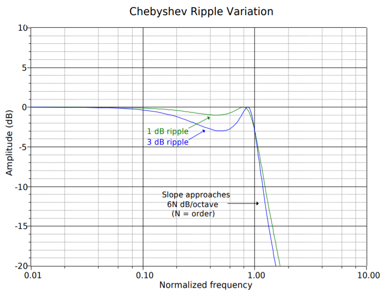
Figure \(\PageIndex{2a}\): Variation of Chebyshev ripple parameter.
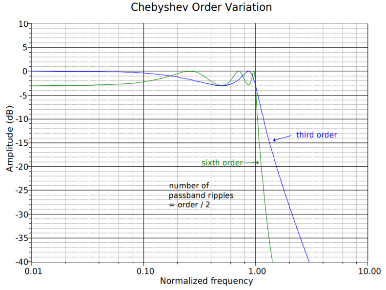
Figure \(\PageIndex{2b}\): Variation of Chebyshev order parameter.
11.5.4: Elliptic
The elliptic is also known as the Cauer alignment. It is a somewhat more advanced filter. It achieves very fast initial rolloff rates. Unlike the other alignments noted above, the elliptic does not “roll off forever”. After its initial transition, the response rises back up, exhibiting ripples in the stop band. A typical response is shown in Figure \(\PageIndex{3}\). The design of elliptics is an advanced topic and will not be considered further. It should be noted, though, that they are popular in analog-todigital conversion systems that require very narrow transition bands.
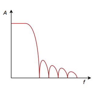
Figure \(\PageIndex{3}\): Elliptic response
11.5.5: Other Possibilities
In order to optimize the time-domain and frequency-domain characteristics for specific applications, a number of other alignments may be used. These include such alignments as Paynter and Linkwitz-Reilly and are often treated as being midway between Bessel and Butterworth, or Butterworth and Chebyshev.