11.1: Introduction
- Page ID
- 31005

Cellular manufacturing systems provide an alternative organization to serial lines and job shops for producing products. Manufacturing is reorganized into cells that provide the operational benefits of a serial line. Each cell performs all of the processing needed on one, or at most a few, similar part types. Each part is processed in the same sequence through a series of machines or manual operations. Cellular manufacturing is effective whenever production volumes are sufficiently high to justify dedicated equipment and only a short series of production steps are required.
For example, the job shop discussed in chapters 8 and 10 could be reorganized into 3 cells, one for each of the three part types. Each cell would behave like the serial line discussed in chapter 7. Each cell would have a sufficient number of each kind of machine to process the type of part for which it was responsible.
Notice that the cellular manufacturing approach eliminates, or at least reduces, the need for setups, since only one part or a small number of similar parts are processed in a particular cell.
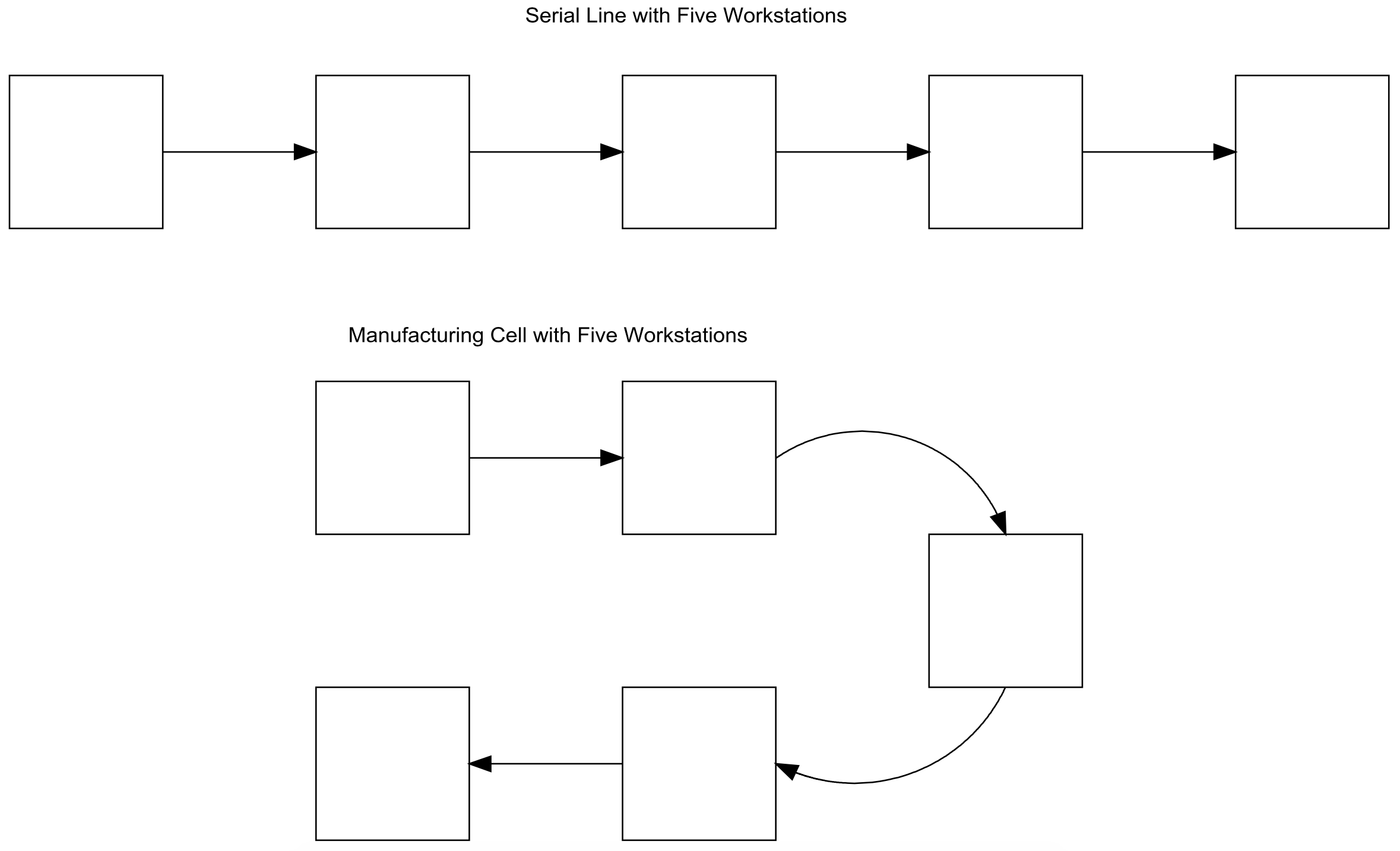
Cellular manufacturing seeks to minimize the movement distance of parts within a cell. In addition, each worker in a cell may support multiple operations at several workstations. Thus, each workstation and its machines must be placed in close proximity with all other workstations. A straight line layout results in the first workstation being too distant from the last workstation. Alternative, a U-shaped layout is often used to meet the workstations close together requirement. This is illustrated in Figure 11-1.
Figure 11-1: Comparison between Serial Line and Manufacturing Cell Layouts
Some companies, such as Innotech, organize all production into cells. Each cell is operated by its workers as an independent business. The businesses share some common resources such as shipping docks and material handling equipment. Rubich and Watson (1998) give some advantages of this approach.
- Improved communication and teamwork - operators are close enough to talk and help each other if necessary.
- An understanding of the entire manufacturing process from raw material to finished product
- An opportunity to meet and discuss issues with customers if any customer concerns develop
- An environment where cell operators have a greater sense of control in how their business (cell) is run
- Responsibility and ownership for producing high quality products on time
- Higher job satisfaction through increased job responsibility and variety
Another goal of cellular manufacturing is to minimize the work-in-process inventory. This is accomplished using the principle of one piece flow that seeks to move individual parts through a work cell as quickly as possible. A worker seeks to keep one piece or part moving through the entire cell. This is the opposite approach to processing multiple parts (a batch) at one workstation and then moving the entire batch to the next workstation for processing. In other words, one piece flow uses a batch size of one.
One piece flow can be used to minimize WIP which results in shorter lead time according to Little's Law. Required manufacturing space is reduced through better layouts and WIP reduction, which also simplifies material handling.
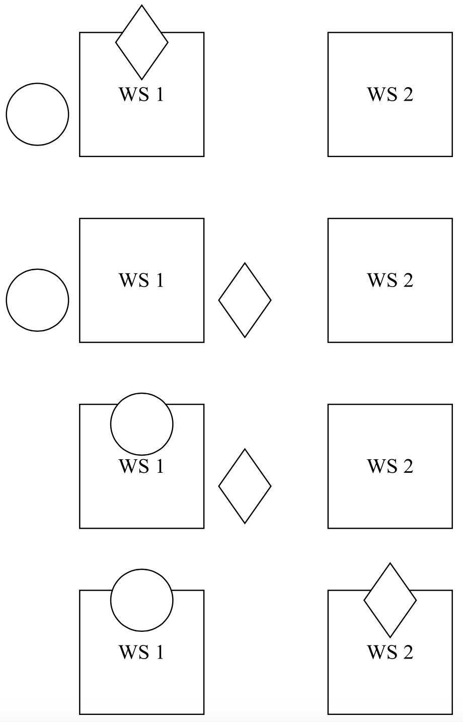
One piece flow works as shown for two stations in Figure 11-2. Initially, the diamond part has completed processing at WS1 and the circle part is waiting in the buffer. The worker arrives to WS1. First the worker removes the diamond part from the machine. Next the worker initiates the circle part on the machine. Finally, the worker moves the diamond part to WS2 and then initiates that part on the machine.
Cellular manufacturing employs a pull strategy. The number of parts the cell must produce per day (or week or month) is established based on the known or forecasted demand for parts. The number of available work hours is set. Then the takt time is computed using equation 11-1.
\(\ \begin{align} \text{takt time}=\frac{\text{available work hours per day}}{\text{demand per day}}\tag{11-1}\end{align}\)
The takt time is the maximum time between parts completed by the work cell if demand is to be met. It is also in a sense the mimimum time. If the cell completes parts faster than the takt time, too many parts are made.
The time between completion of parts at the slowest workstation in the cell should not exceed the takt time. This means that the operation time at that workstation should be less than the takt time. Furthermore, one piece flow is assisted greatly by making the operation time at each workstation as close to the same as possible.
This application study presents the use of simulation in determining the staffing for a manufacturing cell. Alternative assignments of workers to machines in the cell are considered. The effect of variation on cell operations is assessed. The use of simulation to evaluate and enhance the original cell staffing plan developed using standard cellular manufacturing computations is shown.
Figure 11-2: One Piece Flow Sequence for Two Parts and Two Stations