
18.3: The Case Study
- Page ID
- 31036

\( \newcommand{\vecs}[1]{\overset { \scriptstyle \rightharpoonup} {\mathbf{#1}} } \)
\( \newcommand{\vecd}[1]{\overset{-\!-\!\rightharpoonup}{\vphantom{a}\smash {#1}}} \)
\( \newcommand{\dsum}{\displaystyle\sum\limits} \)
\( \newcommand{\dint}{\displaystyle\int\limits} \)
\( \newcommand{\dlim}{\displaystyle\lim\limits} \)
\( \newcommand{\id}{\mathrm{id}}\) \( \newcommand{\Span}{\mathrm{span}}\)
( \newcommand{\kernel}{\mathrm{null}\,}\) \( \newcommand{\range}{\mathrm{range}\,}\)
\( \newcommand{\RealPart}{\mathrm{Re}}\) \( \newcommand{\ImaginaryPart}{\mathrm{Im}}\)
\( \newcommand{\Argument}{\mathrm{Arg}}\) \( \newcommand{\norm}[1]{\| #1 \|}\)
\( \newcommand{\inner}[2]{\langle #1, #2 \rangle}\)
\( \newcommand{\Span}{\mathrm{span}}\)
\( \newcommand{\id}{\mathrm{id}}\)
\( \newcommand{\Span}{\mathrm{span}}\)
\( \newcommand{\kernel}{\mathrm{null}\,}\)
\( \newcommand{\range}{\mathrm{range}\,}\)
\( \newcommand{\RealPart}{\mathrm{Re}}\)
\( \newcommand{\ImaginaryPart}{\mathrm{Im}}\)
\( \newcommand{\Argument}{\mathrm{Arg}}\)
\( \newcommand{\norm}[1]{\| #1 \|}\)
\( \newcommand{\inner}[2]{\langle #1, #2 \rangle}\)
\( \newcommand{\Span}{\mathrm{span}}\) \( \newcommand{\AA}{\unicode[.8,0]{x212B}}\)
\( \newcommand{\vectorA}[1]{\vec{#1}} % arrow\)
\( \newcommand{\vectorAt}[1]{\vec{\text{#1}}} % arrow\)
\( \newcommand{\vectorB}[1]{\overset { \scriptstyle \rightharpoonup} {\mathbf{#1}} } \)
\( \newcommand{\vectorC}[1]{\textbf{#1}} \)
\( \newcommand{\vectorD}[1]{\overrightarrow{#1}} \)
\( \newcommand{\vectorDt}[1]{\overrightarrow{\text{#1}}} \)
\( \newcommand{\vectE}[1]{\overset{-\!-\!\rightharpoonup}{\vphantom{a}\smash{\mathbf {#1}}}} \)
\( \newcommand{\vecs}[1]{\overset { \scriptstyle \rightharpoonup} {\mathbf{#1}} } \)
\(\newcommand{\longvect}{\overrightarrow}\)
\( \newcommand{\vecd}[1]{\overset{-\!-\!\rightharpoonup}{\vphantom{a}\smash {#1}}} \)
\(\newcommand{\avec}{\mathbf a}\) \(\newcommand{\bvec}{\mathbf b}\) \(\newcommand{\cvec}{\mathbf c}\) \(\newcommand{\dvec}{\mathbf d}\) \(\newcommand{\dtil}{\widetilde{\mathbf d}}\) \(\newcommand{\evec}{\mathbf e}\) \(\newcommand{\fvec}{\mathbf f}\) \(\newcommand{\nvec}{\mathbf n}\) \(\newcommand{\pvec}{\mathbf p}\) \(\newcommand{\qvec}{\mathbf q}\) \(\newcommand{\svec}{\mathbf s}\) \(\newcommand{\tvec}{\mathbf t}\) \(\newcommand{\uvec}{\mathbf u}\) \(\newcommand{\vvec}{\mathbf v}\) \(\newcommand{\wvec}{\mathbf w}\) \(\newcommand{\xvec}{\mathbf x}\) \(\newcommand{\yvec}{\mathbf y}\) \(\newcommand{\zvec}{\mathbf z}\) \(\newcommand{\rvec}{\mathbf r}\) \(\newcommand{\mvec}{\mathbf m}\) \(\newcommand{\zerovec}{\mathbf 0}\) \(\newcommand{\onevec}{\mathbf 1}\) \(\newcommand{\real}{\mathbb R}\) \(\newcommand{\twovec}[2]{\left[\begin{array}{r}#1 \\ #2 \end{array}\right]}\) \(\newcommand{\ctwovec}[2]{\left[\begin{array}{c}#1 \\ #2 \end{array}\right]}\) \(\newcommand{\threevec}[3]{\left[\begin{array}{r}#1 \\ #2 \\ #3 \end{array}\right]}\) \(\newcommand{\cthreevec}[3]{\left[\begin{array}{c}#1 \\ #2 \\ #3 \end{array}\right]}\) \(\newcommand{\fourvec}[4]{\left[\begin{array}{r}#1 \\ #2 \\ #3 \\ #4 \end{array}\right]}\) \(\newcommand{\cfourvec}[4]{\left[\begin{array}{c}#1 \\ #2 \\ #3 \\ #4 \end{array}\right]}\) \(\newcommand{\fivevec}[5]{\left[\begin{array}{r}#1 \\ #2 \\ #3 \\ #4 \\ #5 \\ \end{array}\right]}\) \(\newcommand{\cfivevec}[5]{\left[\begin{array}{c}#1 \\ #2 \\ #3 \\ #4 \\ #5 \\ \end{array}\right]}\) \(\newcommand{\mattwo}[4]{\left[\begin{array}{rr}#1 \amp #2 \\ #3 \amp #4 \\ \end{array}\right]}\) \(\newcommand{\laspan}[1]{\text{Span}\{#1\}}\) \(\newcommand{\bcal}{\cal B}\) \(\newcommand{\ccal}{\cal C}\) \(\newcommand{\scal}{\cal S}\) \(\newcommand{\wcal}{\cal W}\) \(\newcommand{\ecal}{\cal E}\) \(\newcommand{\coords}[2]{\left\{#1\right\}_{#2}}\) \(\newcommand{\gray}[1]{\color{gray}{#1}}\) \(\newcommand{\lgray}[1]{\color{lightgray}{#1}}\) \(\newcommand{\rank}{\operatorname{rank}}\) \(\newcommand{\row}{\text{Row}}\) \(\newcommand{\col}{\text{Col}}\) \(\renewcommand{\row}{\text{Row}}\) \(\newcommand{\nul}{\text{Nul}}\) \(\newcommand{\var}{\text{Var}}\) \(\newcommand{\corr}{\text{corr}}\) \(\newcommand{\len}[1]{\left|#1\right|}\) \(\newcommand{\bbar}{\overline{\bvec}}\) \(\newcommand{\bhat}{\widehat{\bvec}}\) \(\newcommand{\bperp}{\bvec^\perp}\) \(\newcommand{\xhat}{\widehat{\xvec}}\) \(\newcommand{\vhat}{\widehat{\vvec}}\) \(\newcommand{\uhat}{\widehat{\uvec}}\) \(\newcommand{\what}{\widehat{\wvec}}\) \(\newcommand{\Sighat}{\widehat{\Sigma}}\) \(\newcommand{\lt}{<}\) \(\newcommand{\gt}{>}\) \(\newcommand{\amp}{&}\) \(\definecolor{fillinmathshade}{gray}{0.9}\)A particular manufacturing plant assembles finished goods from subassemblies that are produced in another area of the plant or delivered to the plant from external suppliers. A subassembly consists of component parts that have been joined together. Subassemblies arrive to the area preceding the final assembly operation as completed or as delivered.
Thus, a buffer before final assembly is required. The buffer is implemented using an AS/RS system. The storage area consists of two rectangular racks of bins with an aisle between them. Each bin holds one subassembly, which may be of one of four types. Subassemblies are delivered to a pick point where they are picked up one at a time by the S/R machine and placed in the nearest, with respect to S/R machine movement time, available bin.
The final assembly process requests subassemblies one at time. Each request specifies a particular type of subassembly. The S/R machine retrieves the nearest, with respect to its movement time, subassembly of the requested type and places it at the drop point. The subassembly is subsequently moved from the drop point to the final assembly area.
To minimize unproductive movements, the S/R machine remains at the bin in which it last placed a subassembly or at the drop point when it completes a task and becomes idle.
Subassemblies arrive from 6:00 A.M. to 2:00 P.M. each day. The final assembly process operates from 8:00 A.M. to 4:00 P.M. each day or until all of the subassemblies in the AS/RS have been consumed.
18.3.1 Define the Issues and Solution Objective
A fundamental issue in the AS/RS control algorithm is into what free bin to store a subassembly and from what occupied bin to retrieve a subassembly. The algorithm to select a bin is an intrinsic component of the operation of the AS/RS system and must be included in the simulation model. Each bin is in one of nine states:
1. Idle
2-5. Occupied with a subassembly of type one, two , three, or four
6-9. Occupied with a subassembly of type one, two, three, or four that is committed to the final assembly process
The selected bin is the one in the specified state that requires the least travel time for the S/R machine. The idle S/R machine waits at the pick point or at the last bin in which a subassembly was stored.
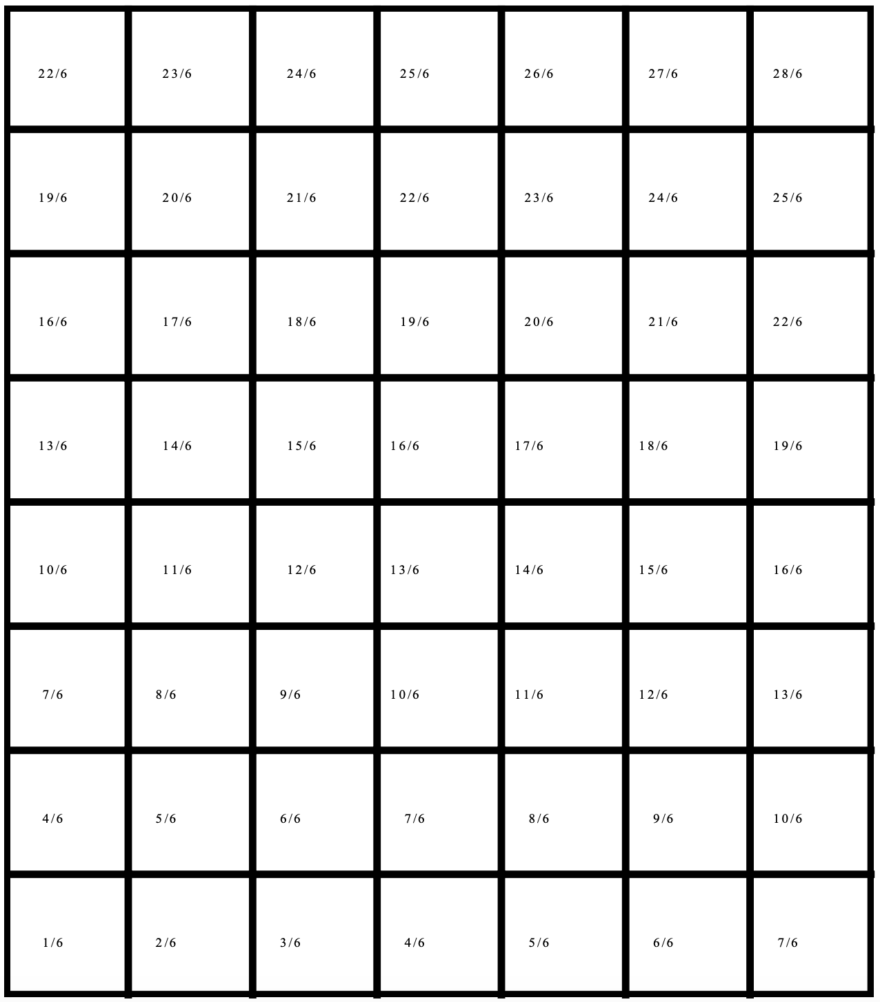
The S/R machine moves 6 feet per second horizontally and 2 foot per second vertically. Each bin is 1 foot square including the rack structure. Thus, the time to reach any bin is the sum of the number of bins traversed horizontally * 1/6 second per bin and the number traversed vertically * 1/2 second per bin. This sum is illustrated for a rack 8 bins high and 7 bins long in Figure 18-2 assuming the S/R machine starts at the pick point which is to the left of the bin structure on the floor level.
The search for a bin is performed by the AS/RS control software. Bins are searched in order of the movement time values shown in Figure 18-2, least to greatest until a bin in the state desired is located. Among bins with the same value, those closer to the floor are preferred.
The same search strategy can be applied if the S/R machine is waiting at a particular bin. The control algorithm searches in four directions, one at a time. These directions are:
- Right and up from the current location, as shown in Figure 18-2.
- Right and down from the current location.
- Left and up from the current location.
- Left and down from the current location.
After all the searches have been completed, the storage location nearest the S/R machine with respect to movement time is chosen.
The search strategy is worthy of discussion. Consider the movement time of 7/6th second. This is the movement time to the seventh bin in the first row, the fourth bin in the second row, and the first bin in the third row. Thus, the bin search order for the time 7/6th second is as listed previously.
Consider searching up and right from the current SR machine location in general. Bins are examined in order of movement time, least to greatest, until a bin in the desired state is found. Bins with equal movement times are searched as follows. The search begins at the bin to the right of the current location and procedes to the bin in the next higher row and three columns preceding (since the vertical movement time is three times the horizontal movement time). This part of the search stops when either a bin in the desired state is found or the next bin to be examined would be to the left of the current location of the SR machine or the next bin to be examined does not exist.
It takes the S/R machine 6 seconds to store or retrieve a subassembly from a bin. The time between requests to store a subassembly is 20 seconds, exponentially distributed, as is the time between requests to retrieve a subassembly.
Two configurations of the AS/RS system have been proposed. In the first, each rack has 180 bins, 10 bins high and 18 bins long. In the other, each rack has 225 bins, 9 bins high and 25 bins long. Thus, extra storage space requires more floor space. The problem is to select between these two alternatives.
Figure 18-2: S/R Machine Movement Time (Seconds)
18.3.2 Build Models
The two operations performed by the AS/RS system are modeled as two separate processes. The first operation stores a subassembly in a bin. The second retrieves a subassembly from a bin.
Entities represent subassemblies to be stored or retreived and have five attributes:
| Type = | Type of subassembly: 1, 2, 3, 4. |
| ArriveTime = | Time of arrival to the AS/RS system. |
| Rack = | Rack in which to store the subassembly: 1 or 2. |
| Row = | Horizontal position of the bin in which to store the subassembly. |
| Column = | Vertical position of the bin in which to store the subassembly. |
A state variable is used to track the state of each bin:: idle, filled with a subassembly of a particular type, or filled with a subassembly of a particular type that is committed to the second manufacturing process. In addition, there is a state variable for each subassembly type modeling the number of units of that type in the racks.
A resource represents the S/R machine. The resource modeling the S/R machine has two attributes indicating its Row and Column location in the rack structure.
The storage of an arriving subassembly is handled as follows. The subassembly waits at the pick point until at least one bin is idle. Which particular idle bin to use is determined by the AS/RS control algorithm which is implemented in the model. Information identifying the location of the bin is recorded in the attributes (Rack, Row, Column) of the subassembly entity.
The subassembly continues to wait until the S/R machine is idle. The S/R machine moves from its current location to the pick point. The S/R machine picks up the subassembly, moves to the selected idle bin, and stores the subassembly in that bin. The S/R machine waits at that bin for its next assignment.
Finally, the state of the system updated. The state of the bin is changed to the type of subassembly stored in the bin. The location of the S/R machine is recorded in its Row and Column attributes. The number of subassemblies of the type just stored is incremented by one.
The process of retrieving a subassembly from a bin is similar to the storage process just described. The request for a subassembly of a particular type waits until there is a subassembly of that type in the AS/RS. The AS/RS system control algorithm selects the bin closest to the current location of the S/R machine containing a subassembly of the desired type. The S/R machines moves to that bin, retrieves the subassembly and procedes to the drop point. The S/R machine becomes idle and remains at the drop point.
Again, the state of the system is updated. The state of the bin from which the subassembly was retrieved is changed to idle. The number of subassemblies of the type just retrieved is decremented by one. The location of the SR machine is recorded.
When it becomes idle, the SR machine resource may need to choose between two jobs: storing a subassembly or retrieving a previously stored one. Management decided that it was most important to keep the second manufacturing process working. Thus, priority is given to requests to retrieve previously stored subassemblies.
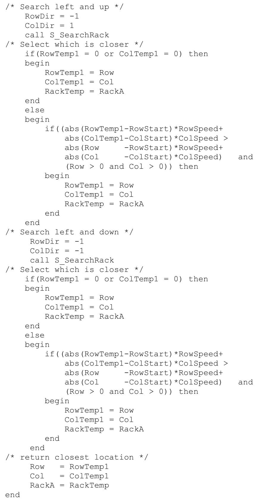
The AS/RS control algorithm is shown in Figures 18-3 a, b, and c.
Figure 18-3a: Control Algorithm Function for Searching in One Direction
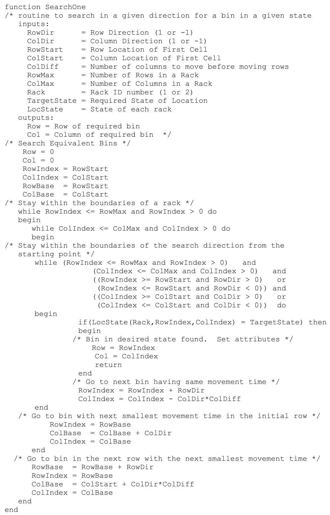
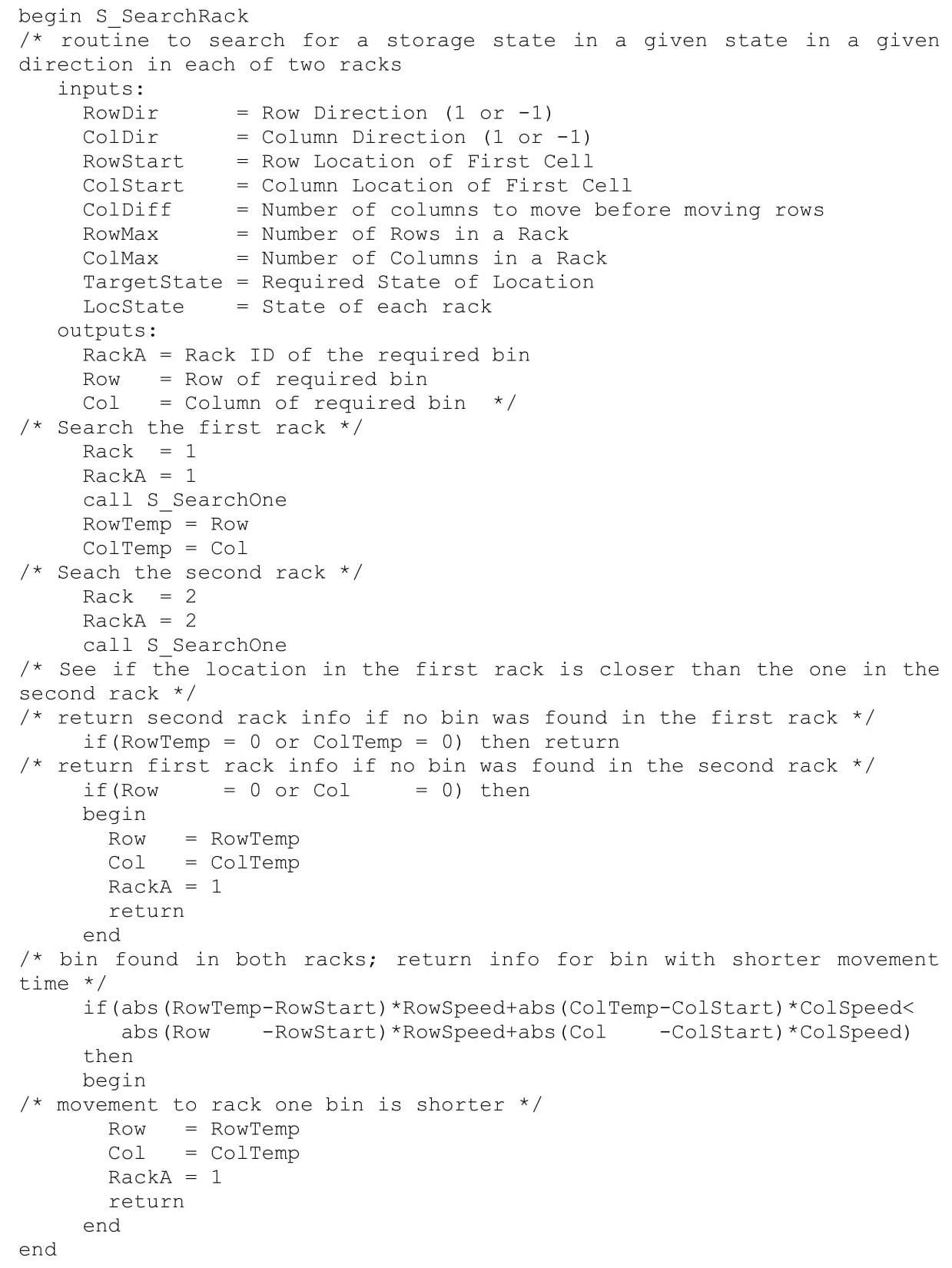
Figure 18-3b: Control Algorithm Function for Determining the Shortest Move Time Among Two Racks
The control algorithm is implemented as three functions. The first searches from the current location of the SR machine given by RowStart and ColStart in any of the four directions given above as specified by RowDir and ColDir. Each of these two variables takes on the values -1 or +1 to define the search direction. The dimensions of a rack are specified in the variables RowMax and ColMax. Which of the two racks to search is specified in the variable Rack which has the value 1 or 2. The variable TargetState gives the state of interest, zero for idle or 1, 2, 3, or 4 for a subassembly of that type. The state of each bin is stored in the three dimensional array LocState(Rack, Row, Col). The variable ColDiff stores the ratio of the horizontal speed to the vertical speed of the SR machine which is three in this case.
The entity attributes Row and Col store the location of the bin in the desired state. If no such bin is found both Row and Col have the value zero.
The other two functions use the same variables as SearchOne. The function SearchRack, shown in Figure 18-3b, searches each rack in one of the directions listed above for a bin and returns the location of the bin that is closest with respect to movement time to the current position of the SR machine. The rack ID number (1 or 2) is returned in the entity attribute RackA.
The function SearchAll, shown in Figure 18-3c, searches in all four directions from the current SR machine location to find the nearest bin in the desired state. The directions are searched one at a time using function SearchRack. After each search, the nearer location so far is determined. The nearest location is returned using the entity attributes Row, Col, and RackA.
The model also contains two processes, Arrival and Retrieval, whose steps were previously described. Pseudo-code for the two processes follows. The same variables defined above for the function SearchOne are also used in the processes. Note that in the Arrival process, the function SearchRack is used instead of SearchAll since the only search direction is up and right of the pick point.
Figure 18-3c: Control Algorithm Function for Determining the Shortest Move Time in Any Direction
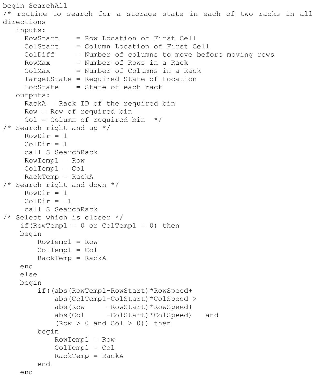
Figure 18-3c: Concluded
| Define Resources \(\ \quad \quad\)SRMach |
// Storage / retrieval (S/R) machine |
| Define Attributes \(\ \quad \quad\)ArriveTime \(\ \quad \quad\)Type |
// Time of arrival of subassembly // Type of subassembly |
| Define Variables \(\ \quad \quad\)Bin InvSA1 \(\ \quad \quad\)InvSA2 \(\ \quad \quad\)InvSA3 \(\ \quad \quad\)InvSA4 \(\ \quad \quad\)RowStart \(\ \quad \quad\)ColumnStart \(\ \quad \quad\)RowDirection \(\ \quad \quad\)ColumnDirection \(\ \quad \quad\)TargetState \(\ \quad \quad\)Rack \(\ \quad \quad\)Row \(\ \quad \quad\)Column \(\ \quad \quad\)VerticalSpeed \(\ \quad \quad\)HorizontalSpeed \(\ \quad \quad\)LocState \(\ \quad \quad\)ColumnMax |
// Bins currently available // Subassemblies of type 1 // Subassemblies of type 2 // Subassemblies of type 3 // Subassemblies of type 4 // Current location of S/R machine - row // Current location of S/R machine - column // Direction of row search // Direction of column search // State of requested bin // Rack with bin in requested state // Row of bin in requested state // Column of bin in requested state // Vertical (column) speed of S/R Machine // Horizontal (row) speed of S/R Machine // State of each bin // Number of columns in a rack |
| Process SubAssembly_Arrivals Define Arrivals \(\ \quad \quad\)Time of first arrival: \(\ \quad \quad\)Time between arrivals: \(\ \quad \quad\)Number of arrivals: Begin \(\ \quad \quad\)Set ArriveTime = Clock \(\ \quad \quad\)Set Type = Integer Uniform (1, 4) \(\ \quad \quad\)Wait until Bin > 0 \(\ \quad \quad\)Increment Bin by 1 \(\ \quad \quad\)Wait until SRMachine is IDLE \(\ \quad \quad\)Make SRMachine BUSY \(\ \quad \quad\)Wait for RowStart*VerticalSpeed + ColumnStart*HorizontalSpeed \(\ \quad \quad\)Set RowStart = 1 \(\ \quad \quad\)Set ColumnStart = 1 \(\ \quad \quad\)Set RowDirection = 1 \(\ \quad \quad\)Set ColumnDirection = 1 \(\ \quad \quad\)Set TargetState = 0 \(\ \quad \quad\)Call SearchRack returning Rack, Row, Column \(\ \quad \quad\)Wait for Row*VerticalSpeed + Column*HorizontalSpeed \(\ \quad \quad\)Wait for 6 seconds \(\ \quad \quad\)Make SRMach IDLE \(\ \quad \quad\)LocState (Rack, Row, Column) = Type \(\ \quad \quad\)Increment InvSA<Type> by 1 End |
0 Exponential 20 seconds Infinite // Move SRMachine to Pick Point // Move SRMachine to Selected Bin // Store Carrier in Bin |
| Process SubAssembly_Retrievals Define Arrivals \(\ \quad \quad\)Time of first arrival: \(\ \quad \quad\)Time between arrivals: \(\ \quad \quad\)Number of arrivals: Begin \(\ \quad \quad\)Set ArriveTime = Clock \(\ \quad \quad\)Set Type = Integer Uniform (1, 4) \(\ \quad \quad\)Wait until InvSA<Type> >0 \(\ \quad \quad\)Decrement InvSA<Type> by 1 \(\ \quad \quad\)Set TargetState = Type \(\ \quad \quad\)Call SearchAll returning Rack, Row, Column \(\ \quad \quad\)Set LocState (Rack, Row, Column) = Type +4 \(\ \quad \quad\)Wait until SRMachine is IDLE \(\ \quad \quad\)Make SRMachine BUSY \(\ \quad \quad\)Wait for abs ((Row - RowStart)*VerticalSpeed) + abs ((Column-ColumnStart)*HorizontalSpeed \(\ \quad \quad\)Wait for abs (Row-1)*VerticalSpeed + abs (Column-ColumnMax)*HorizontalSpeed \(\ \quad \quad\)Make SRMach IDLE \(\ \quad \quad\)Set RowStart = 1 \(\ \quad \quad\)Set ColumnStart = ColumnMax \(\ \quad \quad\)Set LocState(Rack, Row, Column) = 0 End |
2 hours Exponential 20 seconds Infinite // Move SRMachine to Select Bin // Move SRMachine to drop point |
18.3.3 Identify Root Causes and Assess Initial Alternatives
Table 18-1 gives the design for the AS/RS system simulation experiment. The final assembly process consumes all subassemblies stored in the rack each day. Thus, a terminating experiment with the simulated time interval equal to the time each day that the subassemblies arrive to the AS/RS system is appropriate. The dynamics of how the final assembly process consumes the subassemblies remaining in the storage racks after all subassemblies have arrived will not affect the choice of configurations. Thus, this part of the system need not be included in the experiment.
| Element of the Experiment | Values for This Experiment |
| Type of Experiment | Terminating |
| Model Parameters and Their Values | Rack configuration -- (10X18 and 9X25) |
| Performance Measures | 1. Number of bins in non-IDLE states 2. Time subassemblies wait for a bin 3. Time subassemblies and final process requests wait for the SR machine. |
| Random Number Streams | 1. Type of subassembly to store 2. Time between arrivals of subassemblies to the AS/RS system 3. Type of subassembly requested by final assembly 4. Time between arrivals of requests from final assembly |
| Initial Conditions | The bins empty and the SR machine idle |
| Number of Replicates | 20 |
| Simulation End Time | One eight hour day (time in seconds) |
The initial conditions are the daily start-up conditions for the system: all bins empty and the SR machine idle. Twenty replicates will comprise the experiment. There are four random number streams, one each to determine the type of subassembly delivery to the AS/RS and requested by the final assembly process as well as one each for the time between arrivals of subassemblies and requests from the final assembly process.
The model parameter is the rack configuration with the two alternatives proposed by management tested. Performance measures have to do with the utilization of bins, subassembly waiting time for an empty bin, and waiting time for the SR machine to move subassemblies.
Results of this experiment are shown in Table 18-2. The average percent of bins occupied is 16% less for the 9 X 25 rack configuration with an approximate 95% confidence interval of 15% to 18% for the true percent difference. The 9 X 25 rack is 25% bigger than the 10 X 18 rack. Thus, some use is made of the extra bin space. This is reflected in the fact that there is no waiting for an empty bin when the larger rack is used. However, the average waiting time for the smaller rack is only 2.5 seconds with an approximate 95% confidence interval of 0.7 to 4.3 seconds for the true mean waiting time. The average waiting time for the SR machine increases when the larger rack size is used, though the average difference is only 2.4 seconds.
| Percentage of Full Bins | Average Time Waiting for an Empty Bin (Seconds) | Average Time Waiting for the SR Machine (Seconds) | |||||||
| Replicate | 10 X 18 | 9 X 25 | Diff | 10 X 18 | 9 X 25 | Diff | 10 X 18 | 9 X 25 | Diff |
| 1 | 70% | 92% | 22% | 0 | 8.3 | 8.3 | 9.4 | 6.8 | 2.6 |
| 2 | 72% | 92% | 20% | 0 | 8.8 | 8.8 | 9.4 | 6.7 | 2.7 |
| 3 | 71% | 92% | 20% | 0 | 8.2 | 8.2 | 9.5 | 6.7 | 2.8 |
| 4 | 67% | 93% | 27% | 0 | 8.7 | 8.7 | 9.6 | 6.7 | 2.9 |
| 5 | 65% | 92% | 27% | 0 | 8.5 | 8.5 | 9.3 | 6.7 | 2.6 |
| 6 | 72% | 92% | 19% | 0 | 8.2 | 8.2 | 9.4 | 6.7 | 2.7 |
| 7 | 68% | 94% | 26% | 0 | 8.8 | 8.8 | 9.5 | 6.7 | 2.7 |
| 8 | 72% | 93% | 21% | 0 | 8.8 | 8.8 | 9.5 | 6.7 | 2.9 |
| 9 | 73% | 91% | 18% | 0 | 8.9 | 8.9 | 9.5 | 6.7 | 2.9 |
| 10 | 70% | 93% | 23% | 0 | 8.5 | 8.5 | 9.5 | 6.7 | 2.8 |
| 11 | 68% | 92% | 25% | 0 | 8.8 | 8.8 | 9.6 | 6.6 | 3.0 |
| 12 | 69% | 92% | 24% | 0 | 8.4 | 8.4 | 9.5 | 6.8 | 2.7 |
| 13 | 77% | 91% | 14% | 0 | 8.2 | 8.2 | 9.4 | 6.7 | 2.7 |
| 14 | 68% | 92% | 24% | 0 | 8.3 | 8.3 | 8.3 | 6.7 | 2.8 |
| 15 | 63% | 94% | 31% | 0 | 9.0 | 9.0 | 9.6 | 6.7 | 2.9 |
| 16 | 70% | 92% | 22% | 0 | 8.2 | 8.2 | 9.6 | 6.7 | 2.9 |
| 17 | 68% | 93% | 25% | 0 | 8.9 | 8.9 | 9.5 | 6.7 | 2.9 |
| 18 | 74% | 93% | 18% | 0 | 8.5 | 8.5 | 9.3 | 6.7 | 2.6 |
| 19 | 71% | 92% | 22% | 0 | 8.7 | 8.7 | 9.4 | 6.7 | 2.8 |
| 20 | 65% | 92% | 27% | 0 | 8.3 | 8.3 | 9.6 | 6.7 | 2.9 |
| Average | 70% | 92% | 23% | 0 | 8.5 | 8.5 | 9.5 | 6.7 | 2.8 |
| Std. Dev. | 3% | 1% | 3.9% | 0 | 0.28 | 0.28 | 0.088 | 0.043 | 0.10 |
| 99% C.I. Lower Bound |
67% | 92% | 20% | 0 | 8.4 | 8.4 | 9.4 | 6.7 | 2.7 |
| 99% C.I. Upper Bound |
72% | 93% | 25% | 0 | 8.7 | 8.7 | 9.5 | 6.7 | 2.8 |
18.3.4 Review and Extend Previous Work
The smaller rack configuration seems preferable since it would be less costly and require less floor space as long as system performance is not significantly improved by using the larger rack. While the larger rack does eliminate waiting for an empty bin, it increases waiting time for the SR machine. However, no waiting time is very long for either configuration. The bin utilization is relatively high for both rack sizes (92% versus 70%).
18.3.5 Implement the Selected Solution and Evaluate
The AS/RS system with the 10 X 18 configuration of two racks of bins will be implemented. Subassembly waiting at the pick point will be monitored and sufficient buffer space provided as needed.