
2.2: Mechanical analogy of anisotropic response
- Page ID
- 7787
")
A stimulus (such as a force or an electrical field) does not necessarily induce a response (such as a displacement or a current) parallel to it.
This can be demonstrated with a simple mechanical model, consisting of a mass supported by two springs.
Mechanical model: a mass supported by two springs
A force, F, applied at an angle θ, to the central mass acts as the stimulus. The response is the displacement, r, of the mass, at an angle φ.

Diagram showing applied force and resulting displacement
For second rank tensor properties in anisotropic materials, parallel responses occur along orthogonal directions known as the principal directions.
The following photographs show the response of the model under the application of various forces. (Click on an image to view a larger version.)
|
Model with no force applied |
Model with horizontal force producing horizontal displacement (parallel response) (θ = φ = 90º) |
|
Model with vertical force producing vertical displacement (parallel response) (θ = φ = 0º) |
Model with 45º displacement from non-45º force (non-parallel anisotropic response) (θ = approx 35º, φ = 45º) |
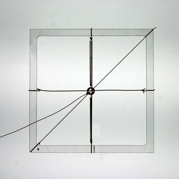
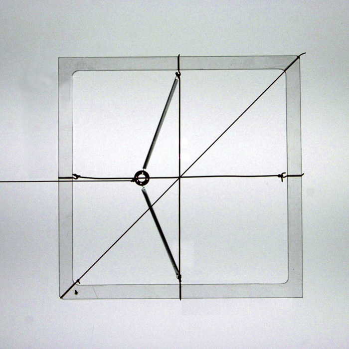
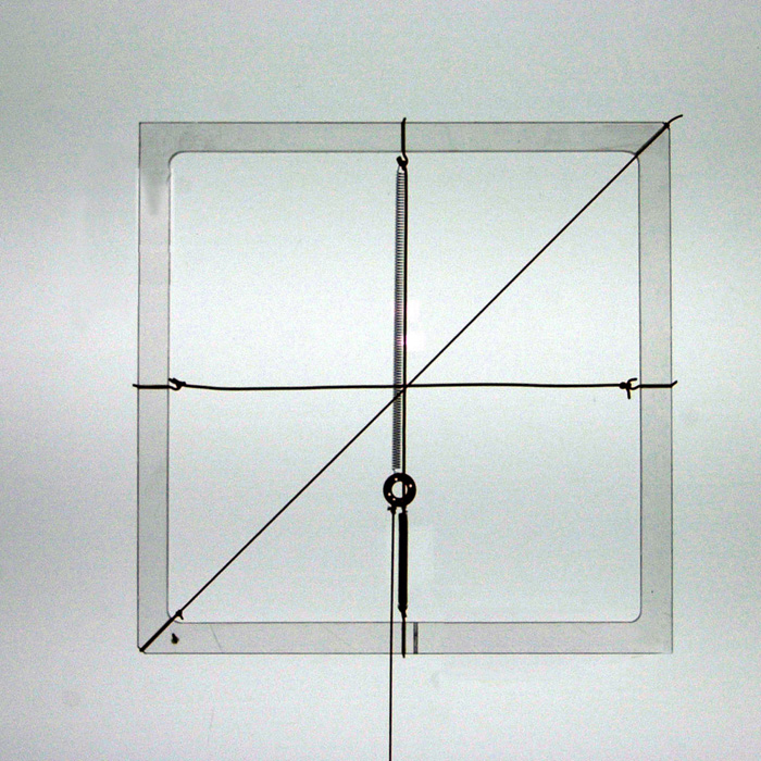
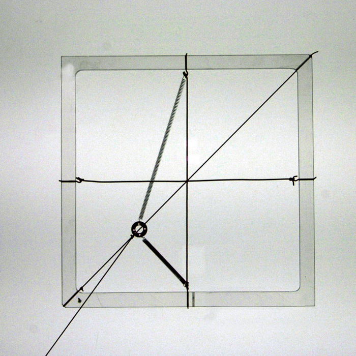
Note that the displacement of the mass is only parallel to the force when the force acts parallel or perpendicular to the springs. These are the directions of the principal axes.
Symmetry
As a rule, the symmetry present in crystalline materials (such as mirror planes and rotational axes) determines or restricts the orientation of the principal axes. In this model, there exist two orthogonal mirror planes perpendicular to the plane of the model, one parallel and the other perpendicular to the springs, and a third mirror plane exists in the plane of the model. The principal axes lie along the intersections of these mirror planes. Real crystals typically show more complicated symmetry, but the orientation of the principal axes is still determined by the main symmetry elements.
Anisotropic properties may be analysed by resolving onto these principal axes.
The symmetry elements of any physical property of a crystal must include the symmetry elements of the point group of the crystal (Neumann’s Principle). Thus crystals that, for example, display spontaneous polarization (see later section on anisotropic dielectric permittivity) can belong to only a few symmetry classes. It is worth noting that the absence of a centre of symmetry does not necessarily imply anisotropic second rank tensor properties, nor does the presence of a centre of symmetry rule out anisotropy in such properties.