Engineering LibreTexts

6.1.3: Initial and Steady-State Analysis of RC Circuits

  • Page ID
    76873
  • \( \newcommand{\vecs}[1]{\overset { \scriptstyle \rightharpoonup} {\mathbf{#1}} } \)

    \( \newcommand{\vecd}[1]{\overset{-\!-\!\rightharpoonup}{\vphantom{a}\smash {#1}}} \)

    \( \newcommand{\id}{\mathrm{id}}\) \( \newcommand{\Span}{\mathrm{span}}\)

    ( \newcommand{\kernel}{\mathrm{null}\,}\) \( \newcommand{\range}{\mathrm{range}\,}\)

    \( \newcommand{\RealPart}{\mathrm{Re}}\) \( \newcommand{\ImaginaryPart}{\mathrm{Im}}\)

    \( \newcommand{\Argument}{\mathrm{Arg}}\) \( \newcommand{\norm}[1]{\| #1 \|}\)

    \( \newcommand{\inner}[2]{\langle #1, #2 \rangle}\)

    \( \newcommand{\Span}{\mathrm{span}}\)

    \( \newcommand{\id}{\mathrm{id}}\)

    \( \newcommand{\Span}{\mathrm{span}}\)

    \( \newcommand{\kernel}{\mathrm{null}\,}\)

    \( \newcommand{\range}{\mathrm{range}\,}\)

    \( \newcommand{\RealPart}{\mathrm{Re}}\)

    \( \newcommand{\ImaginaryPart}{\mathrm{Im}}\)

    \( \newcommand{\Argument}{\mathrm{Arg}}\)

    \( \newcommand{\norm}[1]{\| #1 \|}\)

    \( \newcommand{\inner}[2]{\langle #1, #2 \rangle}\)

    \( \newcommand{\Span}{\mathrm{span}}\) \( \newcommand{\AA}{\unicode[.8,0]{x212B}}\)

    \( \newcommand{\vectorA}[1]{\vec{#1}}      % arrow\)

    \( \newcommand{\vectorAt}[1]{\vec{\text{#1}}}      % arrow\)

    \( \newcommand{\vectorB}[1]{\overset { \scriptstyle \rightharpoonup} {\mathbf{#1}} } \)

    \( \newcommand{\vectorC}[1]{\textbf{#1}} \)

    \( \newcommand{\vectorD}[1]{\overrightarrow{#1}} \)

    \( \newcommand{\vectorDt}[1]{\overrightarrow{\text{#1}}} \)

    \( \newcommand{\vectE}[1]{\overset{-\!-\!\rightharpoonup}{\vphantom{a}\smash{\mathbf {#1}}}} \)

    \( \newcommand{\vecs}[1]{\overset { \scriptstyle \rightharpoonup} {\mathbf{#1}} } \)

    \( \newcommand{\vecd}[1]{\overset{-\!-\!\rightharpoonup}{\vphantom{a}\smash {#1}}} \)

    \(\newcommand{\avec}{\mathbf a}\) \(\newcommand{\bvec}{\mathbf b}\) \(\newcommand{\cvec}{\mathbf c}\) \(\newcommand{\dvec}{\mathbf d}\) \(\newcommand{\dtil}{\widetilde{\mathbf d}}\) \(\newcommand{\evec}{\mathbf e}\) \(\newcommand{\fvec}{\mathbf f}\) \(\newcommand{\nvec}{\mathbf n}\) \(\newcommand{\pvec}{\mathbf p}\) \(\newcommand{\qvec}{\mathbf q}\) \(\newcommand{\svec}{\mathbf s}\) \(\newcommand{\tvec}{\mathbf t}\) \(\newcommand{\uvec}{\mathbf u}\) \(\newcommand{\vvec}{\mathbf v}\) \(\newcommand{\wvec}{\mathbf w}\) \(\newcommand{\xvec}{\mathbf x}\) \(\newcommand{\yvec}{\mathbf y}\) \(\newcommand{\zvec}{\mathbf z}\) \(\newcommand{\rvec}{\mathbf r}\) \(\newcommand{\mvec}{\mathbf m}\) \(\newcommand{\zerovec}{\mathbf 0}\) \(\newcommand{\onevec}{\mathbf 1}\) \(\newcommand{\real}{\mathbb R}\) \(\newcommand{\twovec}[2]{\left[\begin{array}{r}#1 \\ #2 \end{array}\right]}\) \(\newcommand{\ctwovec}[2]{\left[\begin{array}{c}#1 \\ #2 \end{array}\right]}\) \(\newcommand{\threevec}[3]{\left[\begin{array}{r}#1 \\ #2 \\ #3 \end{array}\right]}\) \(\newcommand{\cthreevec}[3]{\left[\begin{array}{c}#1 \\ #2 \\ #3 \end{array}\right]}\) \(\newcommand{\fourvec}[4]{\left[\begin{array}{r}#1 \\ #2 \\ #3 \\ #4 \end{array}\right]}\) \(\newcommand{\cfourvec}[4]{\left[\begin{array}{c}#1 \\ #2 \\ #3 \\ #4 \end{array}\right]}\) \(\newcommand{\fivevec}[5]{\left[\begin{array}{r}#1 \\ #2 \\ #3 \\ #4 \\ #5 \\ \end{array}\right]}\) \(\newcommand{\cfivevec}[5]{\left[\begin{array}{c}#1 \\ #2 \\ #3 \\ #4 \\ #5 \\ \end{array}\right]}\) \(\newcommand{\mattwo}[4]{\left[\begin{array}{rr}#1 \amp #2 \\ #3 \amp #4 \\ \end{array}\right]}\) \(\newcommand{\laspan}[1]{\text{Span}\{#1\}}\) \(\newcommand{\bcal}{\cal B}\) \(\newcommand{\ccal}{\cal C}\) \(\newcommand{\scal}{\cal S}\) \(\newcommand{\wcal}{\cal W}\) \(\newcommand{\ecal}{\cal E}\) \(\newcommand{\coords}[2]{\left\{#1\right\}_{#2}}\) \(\newcommand{\gray}[1]{\color{gray}{#1}}\) \(\newcommand{\lgray}[1]{\color{lightgray}{#1}}\) \(\newcommand{\rank}{\operatorname{rank}}\) \(\newcommand{\row}{\text{Row}}\) \(\newcommand{\col}{\text{Col}}\) \(\renewcommand{\row}{\text{Row}}\) \(\newcommand{\nul}{\text{Nul}}\) \(\newcommand{\var}{\text{Var}}\) \(\newcommand{\corr}{\text{corr}}\) \(\newcommand{\len}[1]{\left|#1\right|}\) \(\newcommand{\bbar}{\overline{\bvec}}\) \(\newcommand{\bhat}{\widehat{\bvec}}\) \(\newcommand{\bperp}{\bvec^\perp}\) \(\newcommand{\xhat}{\widehat{\xvec}}\) \(\newcommand{\vhat}{\widehat{\vvec}}\) \(\newcommand{\uhat}{\widehat{\uvec}}\) \(\newcommand{\what}{\widehat{\wvec}}\) \(\newcommand{\Sighat}{\widehat{\Sigma}}\) \(\newcommand{\lt}{<}\) \(\newcommand{\gt}{>}\) \(\newcommand{\amp}{&}\) \(\definecolor{fillinmathshade}{gray}{0.9}\)

    When analyzing resistor-capacitor circuits, always remember that capacitor voltage cannot change instantaneously. If we assume that a capacitor in a circuit is not initially charged, then its voltage must be zero. The instant the circuit is energized, the capacitor voltage must still be zero. If there is no voltage across the device, then it is behaving like a short circuit. We call this the initial state. Thus, we have our first rule regarding RC circuits:

    \[\text{For DC analysis, initially capacitors appear as shorts.} \label{8.8} \]

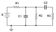
    Consider the circuit of Figure 8.3.1 . Assume that \(C_1\) and \(C_2\) are initially uncharged and there is no voltage across them.

    clipboard_e864192604a689d734d3c1c6e3fa38fe0.png

    Figure 8.3.1 : A basic resistor-capacitor (RC) circuit.

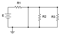
    The instant power is applied, the two capacitors appear as short circuits. If we redraw the circuit for this instant in time, we arrive at the equivalent circuit shown in Figure 8.3.2 .

    clipboard_eaf32039921009b9526c6547131339a45.png

    Figure 8.3.2 : A basic RC circuit, initial state.

    Given this equivalent, we can see that shorting \(C_2\) places \(R_2\) and \(R_3\) in parallel, however, they are both shorted out by \(C_1\). This leaves only \(R_1\) left in the circuit along with the source, \(E\). At this point, currents will begin to flow, and thus begin charging up the capacitors. As the capacitor voltages rise, the current will begin to decrease, and eventually the capacitors will stop charging. At that point no further current will be flowing, and thus the capacitor will behave like an open. We call this the steadystate condition and we can state our second rule:

    \[\text{At steady-state, capacitors appear as opens.} \label{8.9} \]

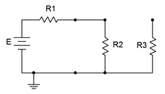
    Continuing with the example, at steady-state both capacitors behave as opens. This is shown in Figure 8.3.3 . This leaves \(E\) to drop across \(R_1\) and \(R_2\). This will create a simple voltage divider. The steady-state voltage across \(C_1\) will equal that of \(R_2\). As \(C_2\) is also open, the voltage across \(R_3\) will be zero while the voltage across \(C_2\) will be the same as that across \(R_2\).

    clipboard_e2213bf5c529b1a8cf50cb0d28a04cad5.png

    Figure 8.3.3 : A basic RC circuit, steady-state.

    In reality, practical capacitors can be thought of as an ideal capacitance in parallel with a very large (leakage) resistance, so there will be a limit to this performance.

    Example 8.3.1

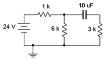
    Given the circuit of Figure 8.3.4 , find the voltage across the 6 k\(\Omega\) resistor for both the initial and steady-state conditions assuming the capacitor is initially uncharged.

    clipboard_e3b725768716acbe76c5fac0ba98871d5.png

    Figure 8.3.4 : Circuit for Example 8.2.4.

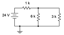
    For the initial state the capacitor is treated as a short. The initial state equivalent circuit is drawn below in Figure 8.3.5 . Immediately apparent is the parallel connection between the 6 k\(\Omega\) and 3 k\(\Omega\) resistors. This combination is equivalent to 2 k\(\Omega\). Therefore, we can perform a voltage divider to find the potential across the 6 k\(\Omega\) (i.e., the 2 k\(\Omega\) combo).

    clipboard_e31bd96123ce986224c5e0380b3df7833.png

    Figure 8.3.5 : Circuit of Figure 8.3.3 , initial state.

    \[V_{6k} = E \frac{R_x}{R_x+R_y} \nonumber \]

    \[V_{6k} = 24 V \frac{2 k\Omega }{2 k\Omega +1 k \Omega } \nonumber \]

    \[V_{6k} = 16 V \nonumber \]

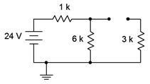
    For the steady-state condition the capacitor will be fully charged, its current will be zero, and we treat it as an open. The steady-state equivalent circuit is drawn below in Figure 8.3.6 .

    clipboard_e5302b8d15181578732401f3da7a5c877.png

    Figure 8.3.6 : Circuit of Figure 8.3.3 , steady-state.

    The 3 k\(\Omega\) resistor is now out of the picture, leaving us with the 6 k\(\Omega\) in series with the 1 k\(\Omega\) resistor. Once again, a voltage divider may be used to determine the voltage across the 6 k\(\Omega\).

    \[V_{6k} = E \frac{R_x}{R_x+R_y} \nonumber \]

    \[V_{6k} = 24 V \frac{6k \Omega }{6k \Omega +1 k\Omega } \nonumber \]

    \[V_{6k} = 20.57V \nonumber \]


    This page titled 6.1.3: Initial and Steady-State Analysis of RC Circuits is shared under a CC BY-NC-SA license and was authored, remixed, and/or curated by James M. Fiore.

    • Was this article helpful?