
6.2.7: Exercises
- Page ID
- 76884

\( \newcommand{\vecs}[1]{\overset { \scriptstyle \rightharpoonup} {\mathbf{#1}} } \)
\( \newcommand{\vecd}[1]{\overset{-\!-\!\rightharpoonup}{\vphantom{a}\smash {#1}}} \)
\( \newcommand{\id}{\mathrm{id}}\) \( \newcommand{\Span}{\mathrm{span}}\)
( \newcommand{\kernel}{\mathrm{null}\,}\) \( \newcommand{\range}{\mathrm{range}\,}\)
\( \newcommand{\RealPart}{\mathrm{Re}}\) \( \newcommand{\ImaginaryPart}{\mathrm{Im}}\)
\( \newcommand{\Argument}{\mathrm{Arg}}\) \( \newcommand{\norm}[1]{\| #1 \|}\)
\( \newcommand{\inner}[2]{\langle #1, #2 \rangle}\)
\( \newcommand{\Span}{\mathrm{span}}\)
\( \newcommand{\id}{\mathrm{id}}\)
\( \newcommand{\Span}{\mathrm{span}}\)
\( \newcommand{\kernel}{\mathrm{null}\,}\)
\( \newcommand{\range}{\mathrm{range}\,}\)
\( \newcommand{\RealPart}{\mathrm{Re}}\)
\( \newcommand{\ImaginaryPart}{\mathrm{Im}}\)
\( \newcommand{\Argument}{\mathrm{Arg}}\)
\( \newcommand{\norm}[1]{\| #1 \|}\)
\( \newcommand{\inner}[2]{\langle #1, #2 \rangle}\)
\( \newcommand{\Span}{\mathrm{span}}\) \( \newcommand{\AA}{\unicode[.8,0]{x212B}}\)
\( \newcommand{\vectorA}[1]{\vec{#1}} % arrow\)
\( \newcommand{\vectorAt}[1]{\vec{\text{#1}}} % arrow\)
\( \newcommand{\vectorB}[1]{\overset { \scriptstyle \rightharpoonup} {\mathbf{#1}} } \)
\( \newcommand{\vectorC}[1]{\textbf{#1}} \)
\( \newcommand{\vectorD}[1]{\overrightarrow{#1}} \)
\( \newcommand{\vectorDt}[1]{\overrightarrow{\text{#1}}} \)
\( \newcommand{\vectE}[1]{\overset{-\!-\!\rightharpoonup}{\vphantom{a}\smash{\mathbf {#1}}}} \)
\( \newcommand{\vecs}[1]{\overset { \scriptstyle \rightharpoonup} {\mathbf{#1}} } \)
\( \newcommand{\vecd}[1]{\overset{-\!-\!\rightharpoonup}{\vphantom{a}\smash {#1}}} \)
\(\newcommand{\avec}{\mathbf a}\) \(\newcommand{\bvec}{\mathbf b}\) \(\newcommand{\cvec}{\mathbf c}\) \(\newcommand{\dvec}{\mathbf d}\) \(\newcommand{\dtil}{\widetilde{\mathbf d}}\) \(\newcommand{\evec}{\mathbf e}\) \(\newcommand{\fvec}{\mathbf f}\) \(\newcommand{\nvec}{\mathbf n}\) \(\newcommand{\pvec}{\mathbf p}\) \(\newcommand{\qvec}{\mathbf q}\) \(\newcommand{\svec}{\mathbf s}\) \(\newcommand{\tvec}{\mathbf t}\) \(\newcommand{\uvec}{\mathbf u}\) \(\newcommand{\vvec}{\mathbf v}\) \(\newcommand{\wvec}{\mathbf w}\) \(\newcommand{\xvec}{\mathbf x}\) \(\newcommand{\yvec}{\mathbf y}\) \(\newcommand{\zvec}{\mathbf z}\) \(\newcommand{\rvec}{\mathbf r}\) \(\newcommand{\mvec}{\mathbf m}\) \(\newcommand{\zerovec}{\mathbf 0}\) \(\newcommand{\onevec}{\mathbf 1}\) \(\newcommand{\real}{\mathbb R}\) \(\newcommand{\twovec}[2]{\left[\begin{array}{r}#1 \\ #2 \end{array}\right]}\) \(\newcommand{\ctwovec}[2]{\left[\begin{array}{c}#1 \\ #2 \end{array}\right]}\) \(\newcommand{\threevec}[3]{\left[\begin{array}{r}#1 \\ #2 \\ #3 \end{array}\right]}\) \(\newcommand{\cthreevec}[3]{\left[\begin{array}{c}#1 \\ #2 \\ #3 \end{array}\right]}\) \(\newcommand{\fourvec}[4]{\left[\begin{array}{r}#1 \\ #2 \\ #3 \\ #4 \end{array}\right]}\) \(\newcommand{\cfourvec}[4]{\left[\begin{array}{c}#1 \\ #2 \\ #3 \\ #4 \end{array}\right]}\) \(\newcommand{\fivevec}[5]{\left[\begin{array}{r}#1 \\ #2 \\ #3 \\ #4 \\ #5 \\ \end{array}\right]}\) \(\newcommand{\cfivevec}[5]{\left[\begin{array}{c}#1 \\ #2 \\ #3 \\ #4 \\ #5 \\ \end{array}\right]}\) \(\newcommand{\mattwo}[4]{\left[\begin{array}{rr}#1 \amp #2 \\ #3 \amp #4 \\ \end{array}\right]}\) \(\newcommand{\laspan}[1]{\text{Span}\{#1\}}\) \(\newcommand{\bcal}{\cal B}\) \(\newcommand{\ccal}{\cal C}\) \(\newcommand{\scal}{\cal S}\) \(\newcommand{\wcal}{\cal W}\) \(\newcommand{\ecal}{\cal E}\) \(\newcommand{\coords}[2]{\left\{#1\right\}_{#2}}\) \(\newcommand{\gray}[1]{\color{gray}{#1}}\) \(\newcommand{\lgray}[1]{\color{lightgray}{#1}}\) \(\newcommand{\rank}{\operatorname{rank}}\) \(\newcommand{\row}{\text{Row}}\) \(\newcommand{\col}{\text{Col}}\) \(\renewcommand{\row}{\text{Row}}\) \(\newcommand{\nul}{\text{Nul}}\) \(\newcommand{\var}{\text{Var}}\) \(\newcommand{\corr}{\text{corr}}\) \(\newcommand{\len}[1]{\left|#1\right|}\) \(\newcommand{\bbar}{\overline{\bvec}}\) \(\newcommand{\bhat}{\widehat{\bvec}}\) \(\newcommand{\bperp}{\bvec^\perp}\) \(\newcommand{\xhat}{\widehat{\xvec}}\) \(\newcommand{\vhat}{\widehat{\vvec}}\) \(\newcommand{\uhat}{\widehat{\uvec}}\) \(\newcommand{\what}{\widehat{\wvec}}\) \(\newcommand{\Sighat}{\widehat{\Sigma}}\) \(\newcommand{\lt}{<}\) \(\newcommand{\gt}{>}\) \(\newcommand{\amp}{&}\) \(\definecolor{fillinmathshade}{gray}{0.9}\)Analysis
1. For the circuit shown in Figure 9.7.1 , determine the effective inductance.
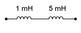
Figure 9.7.1
2. Determine the effective inductance of the network shown in Figure 9.7.2 .
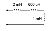
Figure 9.7.2
3. Given the inductor network shown in Figure 9.7.3 , determine the effective value.
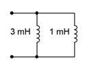
Figure 9.7.3
4. Determine the effective inductance of network shown in Figure 9.7.4 .
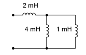
Figure 9.7.4
5. Determine the initial voltage across each component for the circuit shown in Figure 9.7.5 .
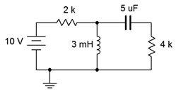
Figure 9.7.5
6. Given the network shown in Figure 9.7.5 , determine the steady-state voltage across each component.
7. Given the network shown in Figure 9.7.6 , determine the steady-state voltage across each component.
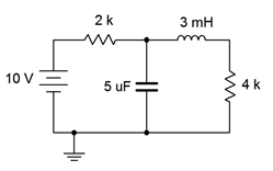
Figure 9.7.6
8. Determine the initial voltage across each component for the circuit shown in Figure 9.7.6 .
9. Given the network shown in Figure 9.7.7 , determine the steady-state voltage across each component.
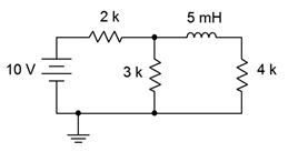
Figure 9.7.7
10. Determine the initial voltage across each component for the circuit shown in Figure 9.7.7 .
11. Determine the initial voltage across each component for the circuit shown in Figure 9.7.8 .
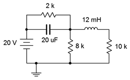
Figure 9.7.8
12. Given the network shown in Figure 9.7.8 , determine the steady-state voltage across each component.
13. Given the network shown in Figure 9.7.9 , determine the steady-state voltage across each component.
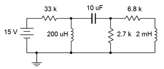
Figure 9.7.9
14. Determine the initial voltage across each component for the circuit shown in Figure 9.7.9 .
15. For the circuit shown in Figure 9.7.10 , determine the inductor current 20 microseconds after the power is switched on. Assume this is an ideal inductor with no internal resistance.
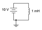
Figure 9.7.10
16. For the circuit shown in Figure 9.7.11 , determine the inductor current 100 milliseconds after the power is switched on. Assume this is an ideal inductor with no internal resistance.
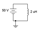
Figure 9.7.11
17. Determine the time constant and the time required to reach steady-state for the circuit shown in Figure 9.7.12 .
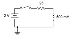
Figure 9.7.12
18. Determine the time constant and the time required to reach steady-state for the circuit shown in Figure 9.7.13 .
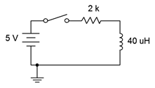
Figure 9.7.13
19. Given the circuit shown in Figure 9.7.2 , determine the inductor voltage and circulating current 200 milliseconds and 2 seconds after the switch is thrown. How does this change if we include 5 \(\Omega\) of internal resistance to the inductor?
20. For the circuit shown in Figure 9.7.13 , determine the inductor voltage and circulating current 50 nanoseconds and 100 milliseconds after the switch is thrown.
21. Determine the time constant and the time required to reach steady-state for the circuit shown in Figure 9.7.14 , switch position 1.
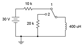
Figure 9.7.14
22. Determine the charge and discharge time constants for the circuit shown in Figure 9.7.15 .
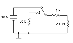
Figure 9.7.15
23. Given the circuit shown in Figure 9.7.14 , determine the inductor current 1 millisecond after the power is turned on. At this point, the switch is thrown to position 2. Determine the inductor voltage the instant of switch contact (assume ideal switch).
24. For the circuit shown in Figure 9.7.15 , determine the inductor current 400 microseconds after the power is turned on. At this point, the switch is thrown to position 2. Determine the inductor voltage the instant of switch contact (assume ideal switch).
25. Determine the time constant and the time required to reach steady-state for the circuit shown in Figure 9.7.16 , switch position 1.
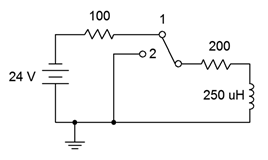
Figure 9.7.16
26. Given the circuit shown in Figure 9.7.16 , determine both the inductor current and voltage 10 milliseconds after the power is turned on. At this point, the switch is thrown to position 2. Determine how long it will take the inductor to discharge to nearly zero amps. Assume ideal switch.
Design
27. For Figure 9.7.12 , determine a new resistor value such that steady-state is reached in 2 milliseconds.
28. For Figure 9.7.13 , determine a new inductor value such that steady-state is reached in 5 microseconds.
Challenge
29. Determine the time constant and the time required to reach steady-state for the circuit shown in Figure 9.7.17 .
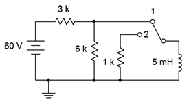
Figure 9.7.17
30. For the circuit shown in Figure 9.7.17 , determine the inductor voltage 400 microseconds after the power is turned on. At this point, the switch is thrown to position 2. Determine how long it will take the inductor to discharge to nearly zero amps. Assume ideal switch.
Simulation
31. Use a transient analysis to verify the time constant and time to steady-state of Figure 9.7.13 (problem 18).
32. Use a transient analysis to verify the inductor voltage waveform of Figure 9.7.12 as specified in problem 19.