
3.3: Heat Engines


- Last updated
- Jul 9, 2022
- Save as PDF
( \newcommand{\kernel}{\mathrm{null}\,}\)
Heat engines are devices that convert thermal energy to mechanical work. They are all around us. They may be quite annoying if you live in the center of a big city. There are many different types. Chronologically, the first types used in industry, used for pulling trains on railroads, and used for propelling commercial and navy vessels were piston steam engines. At the end of the 19th century internal combustion engines were invented – gasoline and diesel engines – and they started gradually replacing steam engines. Some of the “steamers”, though, were die-hards: steam automobiles, the famous Stanley Steamers, were manufactured in the US until the mid-1920-s. Steam railway locomotives were still used in many countries even after the year 1950. And during the World War Two years, between 1941 and 1945, the American shipyards mass-manufactured, at an unprecedented scale, as many as 2710 cargo steamers, known as the U.S. Liberty class ships.
Steam turbines. However, the decline of the piston steam engines coincided with the emergence of a new steam engine type – namely, the steam turbine. They turned out to be particularly useful in devices where huge power was needed: for propelling the largest ships – and in power plants generating hundreds or thousands of megawatts of electric power. The first modern steam turbine was built in 1884 by Sir Charles Parsons (1854-1931). An generator connected to his turbine produced 7.5 kW of electric power. During his lifetime, the power of a single turbine units increased to 50 MW. Today, the two largest existing steam turbines are capable of generating 1,600 MW each.
In today’s global electric power generating system steam turbines are extremely important, indeed. Their main application is in conventional thermal power plants – those fueled by coal, natural gas, or oil. Also, all existing nuclear power plants utilize them: nuclear reactors are only generating heat, later used for making steam sent to turbines. And they are also vital components in some renewable energy systems – in solar power plants based on the technology of Concentrated Solar Power (CSP). Altogether, power plants using steam turbines generate more than 50% of electric power currently consumed worldwide.
Because of the leading role of turbines in power generation, we will not discuss the design or functioning of piston engines here, no matter what type they are steam, petrol or diesel. For students who are strongly interested in such engines, we can recommend an instructive Web site in which 20 animated schemes of piston engines (plus one of a jet engine) are shown. It’s also recommended to pay special attention to the Newcomen Atmospheric engine in this Web page. You may also want to see this Web page. The Newcomen Engine, designed in 1712, was the very first thermal engine that found a wide application in mining industry (several hundred of them were built throughout the 18th Century. Their construction and the operation principle were very simple – not to say “primitive”. So why it’s worth paying attention to such an engine? Well, because of the simplicity of its operation, it’s pretty straightforward to calculate its thermal efficiency (pretty low!), and to discuss where most of the input thermal energy is wasted. It’s a good homework problem!
Let’s go back to the steam turbine. Its spinning part, called rotor, is a sturdy shaft, on which a number of discs are mounted. Each discs has a number of blades attached to its perimeter, as shown in Fig. 3.3.1.
There are additional stationary elements of the turbine assembly, called stator discs, or diaphragms, inserted in between each pair of rotor discs.

A very instructive figures explaining how a rotor and the stator “halfdisc” are mounted in the turbine casing are shown in this Web page – see Figs. 6.19 and 6.21 in this document (essentially, the page is about gas turbines – but the arrangement of the rotor and stator elements is the same in both turbine types). The role of the stators is explained pretty well by an animation in this Technology Partnership Web page. In the animated graph seen in this page right after it opens up, there is a picture of a steam turbine with two rotor disc, and one stator disc in between. The steam that leaves the nozzles, moving (if looked at from the top of the picture) “to the right”. It enters the spaces between the blades of the first rotor disc and passes some of its momentum to the blades. But in the process the steam is “redirected”: now, looking from the top of the picture, it moves “to the left”. But the next rotor disc again “expects” the incoming steam to “arrive from the right”. And this is why the stator disc is for: the steam enters the spaces between the blades moving “to the left”, but due to the curvature of the blades, it’s redirected and leaves the stator disc “moving to the right”.

Another graph explaining the role of the stator blades is shown in Fig. 3.3.2. The rotor blades are the purple ones, and the stator blades are green. The steam arriving from the left is first “redirected” up by the green static blades – so that they can “push” the purple rotor blades “downwards”. But after exiting the space between the rotor blades, the steam moves “upwards”. So, another passage between static blades redirects it “downwards” again – and so on.
In the Fig. 3.3.1 one can see that the turbine rotor has a sophisticated shape – in the region where the steam enters it has a small diameter, which gradually increases, and becomes much larger where the steam exits. Why is it so? As the steam gradually passes its energy to the turbine rotor, its temperature and its pressure decreases. Decreasing pressure of a gas causes it to expand in volume; decreasing temperature has an opposite effect. But in a steam turbine the pressure drop has a far stronger effect than the temperature drop – therefore, the net effect is that the volume of the steam strongly increases in the course of its passage through the turbine – and therefore the last rotor disc is so much larger that the first one.
The turbine is only one part of a complete thermal power plant. A simplified scheme of a complete installation is shown in the Fig. 3.3.3. It must include, of course, a “steam source”. By tradition, it’s called boiler. In the old days, the boilers were huge water tanks mounted on the top of coal furnaces. Inside the tank, water was boiling – usually at pressure much higher than the atmospheric pressure. After “doing its work” in the engine, the exhaust steam was simply released into the air. When most water was used up, the tank had to be opened and refilled with fresh water. It was an inconvenient and time-consuming procedure. A significant improvement was the invention of a condenser. Now, the system became a “closed-loop” one: the exhaust steam was cooled down so it condensed back to liquid water, which was then re-injected by a special pump back into the boiler.

Next, the engineers realized that a big-volume boiler was not necessary. Once the water circulated, a tank could be replaced by a system of coiled tubes. It had an additional advantage that higher pressure could be used. So, water could be heated up to higher and higher temperatures – up to the so called critical point, which for water occurs at 374◦C (647 K), at pressure 218 times the atmospheric pressure (below the critical point water may still exist in liquid form; above it, only in gas form). And it was good, considering that the efficiency of a turbine increases with the increasing steam temperature (it will be discussed in closer detail in the next Section).
Finally, the engineers realized that not only liquid water could be heated. If increasing the steam temperature improves the efficiency, why don’t we heat up the steam even more? – was their thinking. What was needed for that, was just adding more tubes to the “tank-less” boiler. And so the newest generation boilers were born. They produce the so-called superheated steam, of temperature about 550◦C (823 K).
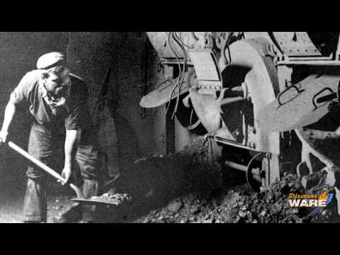
Also, the furnaces underwent a gradual evolution: in the old days, the coal was shuffled manually into them by workers called stokers – you may see them, e.g., in this YouTube clip about the Titanic steam engines, starting at 1 minute 38 seconds (by the way, in the same YouTube one can hear that the steam pressure in the boilers supplying the Titanic’s giant piston-engines was 215 pounds per square inch (PSI), which is 14.6 atmospheres – and today the inlet steam pressure in state-of-the art steam turbines may be more than 10 times higher).
Gradually, the stokers were replaced by conveyor belts. And in the most advanced installations, coal is first the coal is first pulverized into fine dust, and then injected into the furnace using a jet of compressed air.
The alternative of using coal is to fuel the boilers with oil and natural gas. Especially, the latter option is attractive, because – as was shown in the preceding section – natural gas produces at least 3 times less CO2 than coal for the same amount of power generated. Another reason is the ease of fuel transportation, gas can be delivered to the plant by a pipeline. Therefore, more and more coal-fired power plants in the US are being converted to natural gas fuel.
Gas turbines. The conversion of a coal-fired power plant to a gas-fired one involves changing the coal-burning furnace to a system of gas burners. The other parts of the boiler may stay. However, in principle it’s possible to make a “deep conversion” in which the entire boiler and even the steam turbine is removed. The steam turbine may be replaced by a gas turbine that does not need any boiler!
In a gas turbine, air and natural gas of ambient temperature are pumped into a combustion chamber, where they are ignited. Natural gas is essentially a pure methane CH4, and air is a mixture of 21% of oxygen (O2), 78% of nitrogen (M2), and 1% of argon ((Ar). Nitrogen and argon do not take part in the combustion reaction, and methane and oxygen change in the process to CO2 and water vapor. Due to the high heat of combustion of natural gas, the temperature of the mixture of gases after the reaction is as high as 1600◦C, and its pressure increases considerably. From the combustion chamber, it passes to the turbine, which has a very similar design to a steam turbine. The main difference is the temperature. In the latter, the inlet steam temperature is 550◦C, or sometimes a bit higher – but it’s still a temperature tolerated by steel. In a gas turbine, the blades must tolerate a much higher temperature of inlet gases, so they have to be made of special alloys. But besides, the design and operation of both types of turbines are very similar. As mentioned, the largest existing steam turbines can produce as much power as 1600 MW. Currently, single-unit gas turbines with record-high performance made by Siemens yield less, nearly 600 MW – but as far as their efficiency is concerned, they outperform steam turbines. The latter, when running on extremely high-temperature steam, may reach up to 35% efficiency, while from a single-unit gas turbine one can get even 45%.
And this is not the end, because gas turbines offer the possibility of working “in team” in combination with steam turbines, and then the efficiency of such a co-generation assembly may exceed 60%. How such a combination is set up, is explained in the Fig. 3.5.
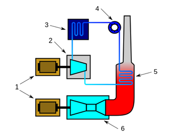
The idea is simple: the exhaust gases from a gas turbine are still pretty hot (450 - 650◦C), which is an ideal steam temperature for a modern steam turbine. Therefore, the exhaust gases are used for generating steam – much like in a boiler in a conventional power plant using steam turbines only. In practice, the power ratio of the two turbines making a “tandem” is close to 2:1. For instance, a typical combination is a 400 MW set consisting of a 270 MW primary gas turbine and a 130 MW secondary steam turbine. On April 28, 2016, a plant in in Bouchain, France, was certified by Guinness World Records as the worlds most efficient combined cycle power plant at 62.22%. However, General Electric is expecting to break the 65% level soon. Note that 65% means generating twice as much electricity from the same amount of gas fuel than a plant using steam turbines only would do. As you see, heat (or, rather thermal energy) from steam can be transformed to mechanical energy. And there is a range of other heat engine types that can be employed to perform many useful tasks (e.g., powering your car).