
6.4: The Physics of a Wind Turbine
- Page ID
- 85108
\( \newcommand{\vecs}[1]{\overset { \scriptstyle \rightharpoonup} {\mathbf{#1}} } \)
\( \newcommand{\vecd}[1]{\overset{-\!-\!\rightharpoonup}{\vphantom{a}\smash {#1}}} \)
\( \newcommand{\dsum}{\displaystyle\sum\limits} \)
\( \newcommand{\dint}{\displaystyle\int\limits} \)
\( \newcommand{\dlim}{\displaystyle\lim\limits} \)
\( \newcommand{\id}{\mathrm{id}}\) \( \newcommand{\Span}{\mathrm{span}}\)
( \newcommand{\kernel}{\mathrm{null}\,}\) \( \newcommand{\range}{\mathrm{range}\,}\)
\( \newcommand{\RealPart}{\mathrm{Re}}\) \( \newcommand{\ImaginaryPart}{\mathrm{Im}}\)
\( \newcommand{\Argument}{\mathrm{Arg}}\) \( \newcommand{\norm}[1]{\| #1 \|}\)
\( \newcommand{\inner}[2]{\langle #1, #2 \rangle}\)
\( \newcommand{\Span}{\mathrm{span}}\)
\( \newcommand{\id}{\mathrm{id}}\)
\( \newcommand{\Span}{\mathrm{span}}\)
\( \newcommand{\kernel}{\mathrm{null}\,}\)
\( \newcommand{\range}{\mathrm{range}\,}\)
\( \newcommand{\RealPart}{\mathrm{Re}}\)
\( \newcommand{\ImaginaryPart}{\mathrm{Im}}\)
\( \newcommand{\Argument}{\mathrm{Arg}}\)
\( \newcommand{\norm}[1]{\| #1 \|}\)
\( \newcommand{\inner}[2]{\langle #1, #2 \rangle}\)
\( \newcommand{\Span}{\mathrm{span}}\) \( \newcommand{\AA}{\unicode[.8,0]{x212B}}\)
\( \newcommand{\vectorA}[1]{\vec{#1}} % arrow\)
\( \newcommand{\vectorAt}[1]{\vec{\text{#1}}} % arrow\)
\( \newcommand{\vectorB}[1]{\overset { \scriptstyle \rightharpoonup} {\mathbf{#1}} } \)
\( \newcommand{\vectorC}[1]{\textbf{#1}} \)
\( \newcommand{\vectorD}[1]{\overrightarrow{#1}} \)
\( \newcommand{\vectorDt}[1]{\overrightarrow{\text{#1}}} \)
\( \newcommand{\vectE}[1]{\overset{-\!-\!\rightharpoonup}{\vphantom{a}\smash{\mathbf {#1}}}} \)
\( \newcommand{\vecs}[1]{\overset { \scriptstyle \rightharpoonup} {\mathbf{#1}} } \)
\(\newcommand{\longvect}{\overrightarrow}\)
\( \newcommand{\vecd}[1]{\overset{-\!-\!\rightharpoonup}{\vphantom{a}\smash {#1}}} \)
\(\newcommand{\avec}{\mathbf a}\) \(\newcommand{\bvec}{\mathbf b}\) \(\newcommand{\cvec}{\mathbf c}\) \(\newcommand{\dvec}{\mathbf d}\) \(\newcommand{\dtil}{\widetilde{\mathbf d}}\) \(\newcommand{\evec}{\mathbf e}\) \(\newcommand{\fvec}{\mathbf f}\) \(\newcommand{\nvec}{\mathbf n}\) \(\newcommand{\pvec}{\mathbf p}\) \(\newcommand{\qvec}{\mathbf q}\) \(\newcommand{\svec}{\mathbf s}\) \(\newcommand{\tvec}{\mathbf t}\) \(\newcommand{\uvec}{\mathbf u}\) \(\newcommand{\vvec}{\mathbf v}\) \(\newcommand{\wvec}{\mathbf w}\) \(\newcommand{\xvec}{\mathbf x}\) \(\newcommand{\yvec}{\mathbf y}\) \(\newcommand{\zvec}{\mathbf z}\) \(\newcommand{\rvec}{\mathbf r}\) \(\newcommand{\mvec}{\mathbf m}\) \(\newcommand{\zerovec}{\mathbf 0}\) \(\newcommand{\onevec}{\mathbf 1}\) \(\newcommand{\real}{\mathbb R}\) \(\newcommand{\twovec}[2]{\left[\begin{array}{r}#1 \\ #2 \end{array}\right]}\) \(\newcommand{\ctwovec}[2]{\left[\begin{array}{c}#1 \\ #2 \end{array}\right]}\) \(\newcommand{\threevec}[3]{\left[\begin{array}{r}#1 \\ #2 \\ #3 \end{array}\right]}\) \(\newcommand{\cthreevec}[3]{\left[\begin{array}{c}#1 \\ #2 \\ #3 \end{array}\right]}\) \(\newcommand{\fourvec}[4]{\left[\begin{array}{r}#1 \\ #2 \\ #3 \\ #4 \end{array}\right]}\) \(\newcommand{\cfourvec}[4]{\left[\begin{array}{c}#1 \\ #2 \\ #3 \\ #4 \end{array}\right]}\) \(\newcommand{\fivevec}[5]{\left[\begin{array}{r}#1 \\ #2 \\ #3 \\ #4 \\ #5 \\ \end{array}\right]}\) \(\newcommand{\cfivevec}[5]{\left[\begin{array}{c}#1 \\ #2 \\ #3 \\ #4 \\ #5 \\ \end{array}\right]}\) \(\newcommand{\mattwo}[4]{\left[\begin{array}{rr}#1 \amp #2 \\ #3 \amp #4 \\ \end{array}\right]}\) \(\newcommand{\laspan}[1]{\text{Span}\{#1\}}\) \(\newcommand{\bcal}{\cal B}\) \(\newcommand{\ccal}{\cal C}\) \(\newcommand{\scal}{\cal S}\) \(\newcommand{\wcal}{\cal W}\) \(\newcommand{\ecal}{\cal E}\) \(\newcommand{\coords}[2]{\left\{#1\right\}_{#2}}\) \(\newcommand{\gray}[1]{\color{gray}{#1}}\) \(\newcommand{\lgray}[1]{\color{lightgray}{#1}}\) \(\newcommand{\rank}{\operatorname{rank}}\) \(\newcommand{\row}{\text{Row}}\) \(\newcommand{\col}{\text{Col}}\) \(\renewcommand{\row}{\text{Row}}\) \(\newcommand{\nul}{\text{Nul}}\) \(\newcommand{\var}{\text{Var}}\) \(\newcommand{\corr}{\text{corr}}\) \(\newcommand{\len}[1]{\left|#1\right|}\) \(\newcommand{\bbar}{\overline{\bvec}}\) \(\newcommand{\bhat}{\widehat{\bvec}}\) \(\newcommand{\bperp}{\bvec^\perp}\) \(\newcommand{\xhat}{\widehat{\xvec}}\) \(\newcommand{\vhat}{\widehat{\vvec}}\) \(\newcommand{\uhat}{\widehat{\uvec}}\) \(\newcommand{\what}{\widehat{\wvec}}\) \(\newcommand{\Sighat}{\widehat{\Sigma}}\) \(\newcommand{\lt}{<}\) \(\newcommand{\gt}{>}\) \(\newcommand{\amp}{&}\) \(\definecolor{fillinmathshade}{gray}{0.9}\)Let’s consider the question: how much energy does wind carry? It turns out that finding the answer is a pretty straightforward task. Suppose that the wind blows with a speed of \(V\) . Now, let’s put an “imaginary tube” with cross section of \(A\) parallel to the wind’s velocity direction. Let \( \delta t \) be an arbitrarily chosen time period. Over ∆t the air particles the wind carries travel the distance of \(V \times \delta t \), right? So let the length of our tube be \( L = V \times \delta t \)
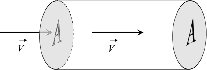
\[ volume = A \times L = A \times V \times \delta t \]
What we need is the mass m of the air inside the tube. The general relation between the mass and the volume is: mass = volume × density. Denoting the density of the air as \(\rho\), we get then:
\[ m=A \times L=A \times V \times \Delta t \times \rho \]
The next step is to find the kinetic energy \(K\) of the air portion inside the tube. All we need is to use the known formula: \(K=m V^{2} / 2\). Combining it with the expression for \(m\) we have gotten, we obtain:
\[ K=\dfrac{A \times \rho \times V^{3}}{2} \Delta t \]
But it is not exactly the energy which is of interest to us - we want to find the power the wind carries. The power, as we know, is:
\[P=\dfrac{\text { the amount of energy delivered }}{\text { the time it took to deliver it }}\]
We have found the energy \(K\) which the "portion" of the air inside the tube carries. How much time it takes it to leave the pipe through its outlet? The length of the pipe is \(L\), and the air inside travels with speed \(V\), so thetime the "portion" in question needs to get completely out through the outlet is:
\[ \dfrac{L}{V}=\dfrac{V \times \Delta t}{V}=\Delta t\]
So, energy \(K\) passes through the tube outlet in time \(\Delta t\). Using then \(K\) from the Eq. 6.1, we the "almost-final" result:
\[P=\dfrac{K}{\Delta t}=\dfrac{A \times \rho \times V^{3} \times \Delta t}{2 \Delta t}=\dfrac{A \times \rho \times V^{3}}{2}\]
Let's check if the unit of \(P\) is correct. There is a convention: \([\mathrm{X}]=\) the unit of \(\mathrm{X}\). Therefore, \([A]=\mathrm{m}^{2} ; \rho]=\mathrm{kg} / \mathrm{m}^{3} ;\) and \([V]=\mathrm{m} / \mathrm{s}\). Hence:
\[ [P]=\mathrm{m}^{2} * \mathrm{~kg} / \mathrm{m}^{3} * \mathrm{~m}^{3} / \mathrm{s}^{3}=\mathrm{kg} * \mathrm{~m}^{2} / \mathrm{s}^{3} \]
which is indeed the unit of power, the Watt, right? ( \(1 \mathrm{~W}=1 \mathrm{~J} / \mathrm{s}=1 \mathrm{~N}^{*} \mathrm{~m} \mathrm{s}\) \(=1\left(\mathrm{~kg} * \mathrm{~m} / \mathrm{s}^{2}\right)^{*} \mathrm{~m} / \mathrm{s}=1 \mathrm{~kg}^{*} \mathrm{~m}^{2} / \mathrm{s}^{3}-\) right!)
The Eq. \(6.2\) is already a useful formula - if we know how big is the area A to which the wind "delivers" its power. For example, is the rotor of a wind turbine is \(R\), then the area in question is \(A=\pi R^{2}\). Sometimes, however, we want to know only how much power the wind carries per a unit surface area - denote it as \(p\). The formula gets even simpler:
\[p=\frac{P}{A}=\frac{A \times \rho \times V^{3}}{2 A}=\frac{\rho \times V^{3}}{2} \]
The air density ρ is a function of temperature and altitude. At sea level and at temperature 15◦ (59◦ F) air has a density of approximately 1.225 kg/m3. The recipe for calculating ρ at other circumstances are given in this Wikipedia article.
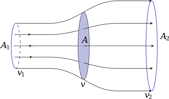
If we know the density of air, the speed of wind, and the radius R of a given turbine, is it enough to find out how much power the turbine deliver, using the Eq. 2? Well... almost. There are still some extra factors. One of them is purely of a physical nature. The problem is that a wind turbine cannot “extract” all kinetic energy from the incoming wind. If it did, what would happen? Well, the kinetic energy of the air after passing the turbine would be zero, meaning also that its velocity would be zero – this is clearly not possible, because the air would start “accumulating” behind the rotor and would start blocking the incoming wind! The air behind the rotor must keep moving! So, what happens to the “downstream” wind? In order to accommodate the slower moving air, the stream behind the rotor has to widen considerably.
Here again is a link to a video explaining the “anatomy” of a wind energy converter – let’s watch it, starting from the 4th minute: the reasons why not all energy carried by the “upstream” wind cannot be “captured” by the turbine is very clearly explained.
Then, how much power can be captured from the wind? This question has been answered in a paper published in 1919 by a German physicist Albert Betz who proved that the maximum fraction of the upstream kinetic energy K that can be “absorbed” by an ideal “actuator” – not necessarily a turbine, but any device capable of converting wind energy to another energy form– is \( \frac{16}{27} \) K, or 59.3% of K. It is known as the Betz Law – and how it can be derived based on the energy, momentum and mass conservation laws is described, for instance, in the Wikipedia article linked.
Let us repeat - \(59.3 \%\) is the maximum fraction, assuming that the "actuator" is an ideal device. In reality, even the best turbines can capture only a fraction of the "Betz maximum". So, in math language - for a turbine rotor of radius \(R\) the maximum theoretical power allowed by the Betz Law is:
\[ P_{\text {Betz } \lim .}=\frac{16}{27} \times \frac{\pi R^{2} \rho V^{3}}{2} \]
And in practice, a turbine delivers only a fraction \(\varepsilon\) of this power, so that the net power obtainable is:
\[ P_{\text {obtainable }}=\frac{16}{27} \times \frac{\pi R^{2} \rho V^{3}}{2} \times \epsilon \]
where \(E\), to make things worse, is not constant, but is the function of something called the "tip-speed ratio" - we will create a TSR symbol for it:
\[ \text { tip speed ratio }=T S R=\frac{\text { Linear speed of the blade tip }}{\text { Wind speed }} \]
We can therefore write the final result for the net windpower harnessed by a turbine:
\[ P_{\text {net }}=\frac{8 \pi R^{2} \rho V^{3}}{27} \times \epsilon \quad \text { where } \epsilon=\epsilon(T S R) . \]
The bad news is that that there is no simple mathematical expression describing the \(\mathcal{E}(T S R)\) function. The shape of this function is different for different rotor types in for each type it has to be determined by experimental measurements.
The results of measurements of the net efficiency \(varepsilon_{\text {net }=P_{\text {net }/P \) plotted versus the Tip Speed Ratio for different types of rotors are presented graphically in a figure uploaded to the ResearchGate.net (a networking site for scientists) by Moshe Zilberman. From the figure it can be seen that the overall efficiency for a modern three-blade rotor has the maximum value of about 46% = 0.46 for the TSR value of about 5.5. By comparing it to the Betz Limit value, 0.593, we find that the value of \( E \) in Eq. 4 for this STR value is 0.46/0.593 = 0.776 = 77.6%, meaning that the turbine converts nearly \( \frac{3}{4}\) of the wind power available by the Betz Law to mechanical power. For the American Multiblade farm windmill the maximum net efficiency is as low as 0.31, corresponding to \( E \) = 52%1. As noted, there is no simple algorithm for calculating the E(TSR) coefficient. However, there is a simple way of dealing with this problem – namely, the power output from a given type of turbine for different wind velocities can be measured experimentally and the results can be stored in an easily accessible database. A known Internet tool of this kind is a Swiss Wind Turbine Power Calculator. It contains the data for more than 50 types of the most popular turbines. After selecting the type, one gets the measured values of the output power of the turbine for speeds of wind from 1 to 30 m/s, with a 1 m/s increment. Such results constitute what is usually referred to as the “power curve” of the given turbine. For instance, for a popular (over 15,000 installed worldwide!) Vestas-80 with “nametag” output of 2,000 kW, the calculator yields:
Table 6.2: The performance of the Vestas-80 turbine
|
Speed of wind (m/s) |
Power output (kW) |
Speed of wind (m/s) |
Power output (kW) |
Speed of wind (m/s) |
Power output (k)W |
|---|---|---|---|---|---|
|
1 |
0 |
11 |
1652 |
21 |
2000 |
|
2 |
0 |
12 |
1892 |
22 |
2000 |
|
3 |
0 |
13 |
1982 |
23 |
2000 |
|
4 |
66 |
14 |
2000 |
24 |
2000 |
|
5 |
156 |
15 |
2000 |
25 |
2000 |
|
6 |
285 |
16 |
2000 |
26 |
0 |
|
7 |
467 |
17 |
2000 |
27 |
0 |
|
8 |
706 |
18 |
2000 |
28 |
0 |
|
8 |
706 |
18 |
2000 |
28 |
0 |
|
9 |
1001 |
19 |
2000 |
29 |
0 |
|
10 |
1329 |
20 |
2000 |
30 |
0 |
As follows from the above discussion, the three-blade turbine, which is dominant type used today, can deliver power as high as over \(75 \%\) of the Betz Limit. It is instructive to confront that with the Power Calculator figures. Let's take, for instant, \(V=10 \mathrm{~m} / \mathrm{s}\), for which the Calculator gives us \(P=\) \(1,329 \mathrm{~kW}\). The rotor diameter of Vestas V8o is 80 meters, so that the radius \(R=40 \mathrm{~m}\), and \(A=\pi R^{2}\) is \(5026.5 \mathrm{~m}^{2}\). The Power Calculator data are for the air density of \(1.225 \mathrm{~kg} / \mathrm{m}^{3}\). For these numbers from the Eq. \(6.2\) one gets \(P=3,078,761 \mathrm{~W}=3,078.8 \mathrm{~kW}\). Correction for the Betz Limit, i.e., multiplication by \(16 / 27\), yields \(1,824.5 \mathrm{~kW}\). It means that the efficiency of the V-8o turbine is \(1.329 / 1,824.5=0.7284=72.8 \%\) - close indeed to the predicted \(75 \%\). But the Reader is encouraged to make similar checks for several other speed of wind values. It turn out that an efficiency close to \(75 \%\) is obtained only at favorable wind conditions: not too weak and not too strong.
One reason for the V8o popularity is that it starts generating electric power at wind velocity as low as only \(4 \mathrm{~m} / \mathrm{s}\). At \(V\) exceeding \(6 \mathrm{~m} / \mathrm{s}\) it's output already is above \(70 \%\) of the Betz Limit (see the rightmost column in the table), but next, for \(V\) exceeding \(10 \mathrm{~m} / \mathrm{s}\), the efficiency starts gradually falling. Why? The answer is simple, the maximum output power the generator in the V-8o turbine is capable to deliver is \(2000 \mathrm{~kW}=2 \mathrm{MW}\). Any electric device has a limit power it can tolerate, otherwise it may overheat or short-circuit. And the power an electric generator delivers depends onhow fast it rotates. Apparently, at wind’s velocity over 13 m/s the generator reaches its maximum allowed speed of rotation. Now, if V keeps increasing, the efficiency of the rotor is artificially lowered, in order not to allow the ro- tor to turn any faster. It can be done by changing the ”pitch” of the blades
– again, we link here the YouTube video where it is shown, 3 minutes and 45 seconds after the beginning, how it is done by rotating the entire blades relative to the rotor hub.
But for wind speed \( \gt 25 \mathrm{~m} / \mathrm{s}\) it is no longer safe to let the rotor turn – so the blades are set to a neutral position in which they generate no torque and a special electromagnetic brake is engaged to completely immobilize the rotor.
___________________________________________________________
1. It should be noted, however, that for millions of farmers who installed American Multiblade turbines not their power, but the torque offered by those windmills was the most important factor. In contrast to two- and three-bladed turbines, the multiblade rotors produce a high torque right from the moment the wind starts blowing – it’s called the “start-up” torque. And the torque is crucial if the turbine is used, for operating a reciprocating water pump – what was their main task at American farms.