
11.4.1.5: Batteries for Industry- and Grid-scale Storage
- Page ID
- 84614
\( \newcommand{\vecs}[1]{\overset { \scriptstyle \rightharpoonup} {\mathbf{#1}} } \)
\( \newcommand{\vecd}[1]{\overset{-\!-\!\rightharpoonup}{\vphantom{a}\smash {#1}}} \)
\( \newcommand{\id}{\mathrm{id}}\) \( \newcommand{\Span}{\mathrm{span}}\)
( \newcommand{\kernel}{\mathrm{null}\,}\) \( \newcommand{\range}{\mathrm{range}\,}\)
\( \newcommand{\RealPart}{\mathrm{Re}}\) \( \newcommand{\ImaginaryPart}{\mathrm{Im}}\)
\( \newcommand{\Argument}{\mathrm{Arg}}\) \( \newcommand{\norm}[1]{\| #1 \|}\)
\( \newcommand{\inner}[2]{\langle #1, #2 \rangle}\)
\( \newcommand{\Span}{\mathrm{span}}\)
\( \newcommand{\id}{\mathrm{id}}\)
\( \newcommand{\Span}{\mathrm{span}}\)
\( \newcommand{\kernel}{\mathrm{null}\,}\)
\( \newcommand{\range}{\mathrm{range}\,}\)
\( \newcommand{\RealPart}{\mathrm{Re}}\)
\( \newcommand{\ImaginaryPart}{\mathrm{Im}}\)
\( \newcommand{\Argument}{\mathrm{Arg}}\)
\( \newcommand{\norm}[1]{\| #1 \|}\)
\( \newcommand{\inner}[2]{\langle #1, #2 \rangle}\)
\( \newcommand{\Span}{\mathrm{span}}\) \( \newcommand{\AA}{\unicode[.8,0]{x212B}}\)
\( \newcommand{\vectorA}[1]{\vec{#1}} % arrow\)
\( \newcommand{\vectorAt}[1]{\vec{\text{#1}}} % arrow\)
\( \newcommand{\vectorB}[1]{\overset { \scriptstyle \rightharpoonup} {\mathbf{#1}} } \)
\( \newcommand{\vectorC}[1]{\textbf{#1}} \)
\( \newcommand{\vectorD}[1]{\overrightarrow{#1}} \)
\( \newcommand{\vectorDt}[1]{\overrightarrow{\text{#1}}} \)
\( \newcommand{\vectE}[1]{\overset{-\!-\!\rightharpoonup}{\vphantom{a}\smash{\mathbf {#1}}}} \)
\( \newcommand{\vecs}[1]{\overset { \scriptstyle \rightharpoonup} {\mathbf{#1}} } \)
\( \newcommand{\vecd}[1]{\overset{-\!-\!\rightharpoonup}{\vphantom{a}\smash {#1}}} \)
\(\newcommand{\avec}{\mathbf a}\) \(\newcommand{\bvec}{\mathbf b}\) \(\newcommand{\cvec}{\mathbf c}\) \(\newcommand{\dvec}{\mathbf d}\) \(\newcommand{\dtil}{\widetilde{\mathbf d}}\) \(\newcommand{\evec}{\mathbf e}\) \(\newcommand{\fvec}{\mathbf f}\) \(\newcommand{\nvec}{\mathbf n}\) \(\newcommand{\pvec}{\mathbf p}\) \(\newcommand{\qvec}{\mathbf q}\) \(\newcommand{\svec}{\mathbf s}\) \(\newcommand{\tvec}{\mathbf t}\) \(\newcommand{\uvec}{\mathbf u}\) \(\newcommand{\vvec}{\mathbf v}\) \(\newcommand{\wvec}{\mathbf w}\) \(\newcommand{\xvec}{\mathbf x}\) \(\newcommand{\yvec}{\mathbf y}\) \(\newcommand{\zvec}{\mathbf z}\) \(\newcommand{\rvec}{\mathbf r}\) \(\newcommand{\mvec}{\mathbf m}\) \(\newcommand{\zerovec}{\mathbf 0}\) \(\newcommand{\onevec}{\mathbf 1}\) \(\newcommand{\real}{\mathbb R}\) \(\newcommand{\twovec}[2]{\left[\begin{array}{r}#1 \\ #2 \end{array}\right]}\) \(\newcommand{\ctwovec}[2]{\left[\begin{array}{c}#1 \\ #2 \end{array}\right]}\) \(\newcommand{\threevec}[3]{\left[\begin{array}{r}#1 \\ #2 \\ #3 \end{array}\right]}\) \(\newcommand{\cthreevec}[3]{\left[\begin{array}{c}#1 \\ #2 \\ #3 \end{array}\right]}\) \(\newcommand{\fourvec}[4]{\left[\begin{array}{r}#1 \\ #2 \\ #3 \\ #4 \end{array}\right]}\) \(\newcommand{\cfourvec}[4]{\left[\begin{array}{c}#1 \\ #2 \\ #3 \\ #4 \end{array}\right]}\) \(\newcommand{\fivevec}[5]{\left[\begin{array}{r}#1 \\ #2 \\ #3 \\ #4 \\ #5 \\ \end{array}\right]}\) \(\newcommand{\cfivevec}[5]{\left[\begin{array}{c}#1 \\ #2 \\ #3 \\ #4 \\ #5 \\ \end{array}\right]}\) \(\newcommand{\mattwo}[4]{\left[\begin{array}{rr}#1 \amp #2 \\ #3 \amp #4 \\ \end{array}\right]}\) \(\newcommand{\laspan}[1]{\text{Span}\{#1\}}\) \(\newcommand{\bcal}{\cal B}\) \(\newcommand{\ccal}{\cal C}\) \(\newcommand{\scal}{\cal S}\) \(\newcommand{\wcal}{\cal W}\) \(\newcommand{\ecal}{\cal E}\) \(\newcommand{\coords}[2]{\left\{#1\right\}_{#2}}\) \(\newcommand{\gray}[1]{\color{gray}{#1}}\) \(\newcommand{\lgray}[1]{\color{lightgray}{#1}}\) \(\newcommand{\rank}{\operatorname{rank}}\) \(\newcommand{\row}{\text{Row}}\) \(\newcommand{\col}{\text{Col}}\) \(\renewcommand{\row}{\text{Row}}\) \(\newcommand{\nul}{\text{Nul}}\) \(\newcommand{\var}{\text{Var}}\) \(\newcommand{\corr}{\text{corr}}\) \(\newcommand{\len}[1]{\left|#1\right|}\) \(\newcommand{\bbar}{\overline{\bvec}}\) \(\newcommand{\bhat}{\widehat{\bvec}}\) \(\newcommand{\bperp}{\bvec^\perp}\) \(\newcommand{\xhat}{\widehat{\xvec}}\) \(\newcommand{\vhat}{\widehat{\vvec}}\) \(\newcommand{\uhat}{\widehat{\uvec}}\) \(\newcommand{\what}{\widehat{\wvec}}\) \(\newcommand{\Sighat}{\widehat{\Sigma}}\) \(\newcommand{\lt}{<}\) \(\newcommand{\gt}{>}\) \(\newcommand{\amp}{&}\) \(\definecolor{fillinmathshade}{gray}{0.9}\)The “size spectrum” of Lithium-ion batteries is very broad, it covers all possible range of sizes – starting from those in miniature portable electronic devices and ending with huge “grid-tied” storage ones with capacities of hundreds of MWh. However, in the latter group there are neither the only possible technology nor the largest existing devices. The lithium-ion technology is the best known because we constantly deal with such batteries. The other types are less known because they exist only as large stationary devices, but not in the portable form. However, they can successfully compete with the li-ion technology offering a number of advantages: lower material costs, much longer “lifespan” calculated in the number of charge/discharge cycles. Below, three such types are presented: Sodium-Sulphur (NAS) batteries, the so-called “redox flow batteries”, and molten metal batteries.
The Sodium-Sulfur (NAS) batteries. They were invented in Ford Motor Company in 1966. Due to their high gravimetric energy density, several times better than that of lead-acid batteries, it was hoped that would allow developing electric vehicles with a range above 100 miles. However, there were several reasons that made the use of such batteries in automobiles highly risky and, last but not least, pretty inconvenient for the car user. But they may be attractive when it comes to stationary energy storage – the best proof for that is that the largest currently (March 2020) existing storage battery is just of the NAS type.
Most of the existing battery types use solid electrodes and liquid electrolytes. In an elementary NAS cell this scheme is reversed – namely, the electrodes are molten sodium metal and sulfur and the electrolyte is a solid ceramic material known as sodium β-alumina. The design of a NAS battery is pretty simple, as illustrated by graphic schemes in this Web page of Zhang’s Research Group or in ScienceDirect Web article. The liquid sodium electrode fills a cylindrical vessel which is made of β-alumina, and this vessel is immersed in molten sulfur contained in a cylindrical vessel of larger diameter.
The β-alumina is a material obtained by sintering aluminum oxide and sodium oxide. Its unique property is that at elevated temperatures it is not permeable for to sodium and sulfur atoms while it permeates sodium ions (a sodium ion Na+ is created when the single outer electrons is “pealed off” a sodium atom – therefore, the ion’s radius is much smaller than that of the atom). In the discharge phase the Na+ ions penetrate the β-alumina partition, “leaving behind” their electrons. Those electrons flow out of molten sodium and through an external circuit they enter the sulfur electrode, where sulfur atoms, sodium ions and electrons react and form molecules of sodium polysulfate Na2S4:
2Na+ + 2e− + 4S → Na2S4
During a recharging process these reactions are reversed.
Note that the NAS batteries are made of widely available and inexpensive components. Their other significant advantages are longevity (if properly exploited, up to 15 years, or 5000 charge/recharge cycles) and high gravimetric energy density, comparable with the best Lithium-ion batteries currently on the market. So, where is the problem?
The problem is the temperature, 300◦ 350◦C that has to be maintained to keep the electrodes molten and the β-alumina partition between them in an ion-conducting state. Well, you may know that since the medieval ages molten sulfur was believed to a terrible substance, used by devils torture the sinners’ souls in the hell. In fact, it is a devilish fluid indeed, highly flammable and emitting toxic and caustic SO2 fumes when burning. And what medieval people were ignorant of – because they had no idea that such a thing as sodium metal does exist – molten 300◦C sodium is even far worse than molten sulfur! One cannot even use water to extinguish it, because water, instead of suppressing the fire, adds fuel to it!
The high temperature would be a major inconvenience for owners of electric vehicles with NAS batteries because heating up the battery pack before taking off in the car would take many minutes. But what might have happened if the the battery pack were damaged in a traffic collision would be an authentic drama!
But dealing with huge scale stationary industrial high-temperature installation is nor a problem and engineers have much necessary experience in this field. In the smelting of iron, ammonia synthesis, cement production, and many other industrial processes furnaces and installations with masses of hundreds or even thousands of tons are heated to temperatures even much, much higher than 300◦C.
Suppose that a storage pack with a capacity of 100 MWh is needed. NAS with energy density as high as 200 Wh/kg are available. So, it would be 5 kg per 1 kWh, 5 000 kg = 5 metric tons for 1 MWh, and 500 metric tons for 100 MWh. It does not seem likely that an engineer would panic when given a task of heating up a 500 ton piece of hardware to 300◦C!
In fact, NAS batteries have been used for building the largest in the world (as of March 2020) electric energy storing facility in Abu Dhabi. Its total capacity is 648 MWh, five times larger than the Tesla-supplied world largest Lithium-ion storage installation in Hornsdale, Australia.
Catastrophic fires may happen in installations using NAS batteries. There was one such serious accident in Tsukuba, Japan on Oct. 21, 2011. It caused a serious disruption in the Japanese energy storage development program. The creators of the Abu Dhabi system demonstrated wisdom and caution by building it not as a single structure, but in the form of 15 separate “blocks” located at a safe distance from one another in a desert terrain. Therefore even in the event of a catastrophic fire in one of them, neither other blocks nor any human settlements will be threatened.
Vanadium redox flow batteries. The word “redox” has been coined from two others, “reduction” and “oxidation”. In chemistry, if an atom loses one or more electrons and becomes a positive ion, such a process is called “oxidation”. The oxidation state of an ion is simply the number of electrons it has lost. Reduction is an opposite process – if an atom gains one or more electrons and becomes a negative ion, the process is called “reduction”. Also, if a positive ion at a high oxidation state gains an electron and still remains a positive ion, but with a lower oxidation state, it’s also called “reduction”.
The oxidation state of an ion is denoted by a number lost electrons written as a right-hand superscript to the chemical symbol of the element in question, followed by the plus sign. The same code may be used for negative ions, i.e., such that gained one or more extra electrons – but then after the number of gained electrons goes a minus sign. So, negative ions are in a negative oxidation state.
Vanadium can occur in various water-soluble compounds in four different oxidation states: V2+, V3+, V4+ and V5+. One more piece of information important for the further discussion is the ionization energy of each of these states – i.e., how much energy is needed for removing the given number of electrons from the atom. These energies are, respectively, 6.7, 14.6, 29.3, 46.7 and 65.3, all in electron-Volts (from the www.webelements.com Web portal where molar enthalpy values of the vanadium oxidation states are given in kJ/mole units – they can be readily converted into individual ion energies in eV using, e.g., this on-line tool).
The exact theory of the vanadium-redox flow battery is pretty sophisticated, so here we will not even try to make a detailed presentation of it. In fact, it’s not needed. The thing that really matters is making it clear how energy is stored in the battery using a possibly simple “pedagogical tools”.
OK, so suppose that there is a liquid containing two types of vanadium ions, V2+ and V5+. Now, what needs to be done to convert a V2+ ion to a V3+ one? Well, the energy of the former is 14.6 eV, and of the latter is 29.3 eV. So, if we want to remove yet another electron from the V2+, an energy input of 29.3 eV 14.6 eV = 14.7 eV is needed. Such a transition process can be described by an equation:
V2+ + 14.7 eV → V3+ + e−
Conversely, an electron can be added to a V5+ ion with the energy of 65.3 eV to lower its oxidation state to V4+ with 46.7 eV of energy. Thus, in the process 65.3 eV 46.7 eV = 18.6 eV of energy will be released. Again, one can write an equation:
V5+ + e− → V4+ + 18.6 eV
Then, suppose that there is a “close encounter” between V2+ and V5+. The two ions may then exchange one electron. An equation describing such a process can be obtained by adding the two above equations, viz.:
V2+ + 14.7 eV + V5+ + e− → V3+ + e− + V4+ + 18.6 eV
After reducing the e− appearing on both sides and grouping the two energies on the right side, we obtain:
V2+ + V5+ → V3+ + V4+ + 3.9 eV
So, in such an encounter between the two ions and “electron swapping” 3.9 eV of energy is released. It means that such a reaction is – as chemists call it – “exothermic”, i.e., energy is released. Exothermic reactions occur spontaneously – therefore, by mixing solutions containing equal numbers of V2+ and V5+ ions, one obtains a mixture containing V3+ and V4+ ions, somewhat warmer than the two initial solutions.
But where is the battery?! – one moment! If we mixed the solutions, the ions would directly swap the electrons. Let’s then keep the solutions in two separate vessels, and give the ions another option of how to swap the electrons. How? By wire! Let’s dip the ends of a wire in the two vessels. Electrons will start flowing down the wire from the vessel containing V2+ ions to the one with the V5+ ions! Hurray! We do have our battery!
Just a moment, just a moment! There is still one problem. If the electrons starts flowing, soon in the “electron donor” vessel a positive charge will start accumulation, and in the “electron acceptor” one negative charge will. Positive charge will tend to pull the electrons back, negative charge will repel them – so, after a brief moment, the current will stop flowing in the wire. Things will work only if we find a method of “neutralizing” the charges that build up.
The credit for solving the problem – end, effectively, for the invention of redox flow battery – goes to an Australian scientist, Maria Skyllas Kazakos. She obtained a patent for the invention in 1986. The ingenious solution of the charge build-up problem was to keep both solution in the same vessel, but separated by a partition permeable to hydrogen ions H+ – they carry the excess positive charge away from the V2+ chamber into the V5+ chamber, where they neutralize the negative charge building up.
But why it’s called a “flow” battery? It’s because fresh solution containing V2+ ions (called the “Anolyte”)and solution containing V5+ ions (called the “Catholyte”) are continually pumped through the reaction chamber, in order to replace the V3+ and V4+ that “have already done their work”. There is one important conclusion that can be reached right away: what is the energy capacity of such a battery? The answer: there is no upper limit! If one needs to increase the energy storage capacity of the battery, it can be done simply by adding more anolyte and catholyte tanks!
We have only discussed the processes in the discharge phase. But the battery is fully rechargeable, instead of drawing current from it, current from an external source should be run through it – while the “spent” anolyte and catholyte are pumped back through the chamber. Over there, the V3+ ions will be converted back to V2+ ones, and the V4+ ions back to V5+ ones.
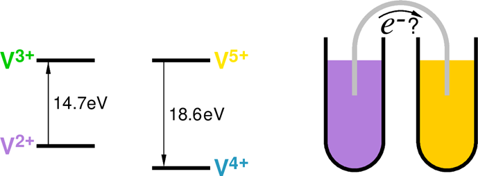
A nice property of vanadium is that each oxidation state gives the solution a distinct color: 2+ is lavender, 3+ is green, 4+ is blue and 5+ is yellow (see, e.g., the picture in this chemicool.com Web page. It makes plotting graphs explaining how VRFBs work, because the four essential different phases of anolyte and catholyte can be shown by distinct colors – see Figs. \(\PageIndex{1}\): and \(\PageIndex{2}\):

A simple concept of a battery shown in Fig. \(\PageIndex{1}\) would not work –unless there is an additional mechanism preventing the build-up of charges in the anoand catho-lyte.
As noted, the problem was solved by Maria Skyllas Kazakos, and a graph explaining in closer detail how her “recipe” works is presented in the Fig. \(\PageIndex{2}\). In both the anolyte and the catholyte the respective V2+ and the V5+ ions are kept in strongly acidic solutions – the reason is to create an environment with an abundance of hydrogen H+ ions. The two solutions are pumped into a “reaction chamber” in which there are two compartments separated by a membrane permeable to H+ ions. In the left compartment, the V2+ V3+ transition occurs and the released electron is picked up by the electrode. Then it continues its trek across the wire to the electrode of the other compartment, from which it enters the catholyte. At the same time a positive hydrogen ion passes through the membrane, thus neutralizing the positive charge created in the chamber by “escape” of the electron.
In the right compartment the V5+ V4+ transition involves a somewhat more complicated process. The thing is that the V5+ ion in the catholyte forms a complex with two negative oxygen ions, V5+O(2−)2. When the V5+ absorbs the electron arriving from the other compartment, it becomes “less positive”, which weakens bonds with the oxygen ions. One of these gets released from the complex, it attaches two hydrogen ions and forms a neutral molecule of water H2O (in the Fig. 11.12 one of these H+ ions is the one arriving from the other compartment; of course, it does not have to be this way, in the catholyte there is an abundance of of other H+ ions). The vanadium ion, now V4+, remains combined with the other oxygen and it becomes a part of the “spent” catholyte.
The “spent” anolyte and catholyte contain, respectively, V2+ and V4+ ions. After leaving the reaction chamber they are stored in separate tanks. In the re-charging phase, all liquids are pumped back through the reaction chamber and current from a recharging source is sent through it – now electrons enter the anolyte compartment, and exit the catholyte compartment. The “refreshed” fluids are returned to their original tanks.
In the scheme in Fig. 11.12 there are four tanks. In literature and in videos on the subject most often a two-tank version is shown, where the spent fluids are returned to the same tanks from which the fresh fluids have been taken. The Author of this book, though, believes that the four-tank version is more “pedagogical”. At least then the question does not arise: and how is mixing of fresh and spent anolyte and catholyte prevented?
There are several short videos on YouTube explaining how redox flow batteries work. The Readers are particularly advised to watch three of them, preferably in the order as listed below:
• Video 1 by Peter Allen, a scientist and blogger;
• Video 2 from a YouTube Channel of Seeker;
• Video 3 by XRG Technologies.
We have paid much attention to the vanadium redox flow battery because it may play an important role in future energy storage systems. A few VRF batteries of single-digit MWh capacity have already been deployed in energystorage facilities (see the Wikipedia list of energy storage projects). One such battery in China is expected to become the record-keeper in 2020, with capacity of 800 GWh, beating the aforementioned 648 GWh of the sulfursodium complex in Abu Dhabi.
China is known to posses the world-richest resources of vanadium ore, which may the reasons for the technology chosen. But vanadium is not inexpensive, so that other countries may show less enthusiasm for the VRF method. The good news, however, is that the VRF battery is only one of the several existing options of redox-flow technology (for review, see, e.g., this article by Dapeng Zhang et al.. In some of those materials considerably cheaper than vanadium compounds can be used – e.g., in all-iron redox flow batteries described below. The reasons why we have chosen to discuss the VRF technology in closer detail are the following: one, because it was the earliest technology implemented in practical energy storage installations, and two, because the “chemistry” underlying the processes involved is arguably the simplest.
Typically, the energy density of redox flow batteries is comparable to that of lead-acid ones. This may not sound particularly impressive today – but it should be kept in mind that redox flow batteries are primarily intended for use not in cars, but in large-scale stationary installations, where maximization of gravimetric/volumetric energy density is not the main goal so it does not necessarily have to be seen as a disadvantage. However, their unquestionable advantages should be emphasized namely, a typical lifetime of 10-20 thousand charge/discharge cycles, the non-flammability of liquids used as anolytes and catholytes, as well as the ease of their recycling if the anolyte gets contaminated with ions from the catholyte, or vice versa.
All-iron redox flow batteries – another candidate for the “Pride of Oregon” title. As noted, the vanadium-based redox flow technology is highly reliable – but the fact that vanadium is neither cheap nor widely available may be a major obstacle to the widespread use of this energy storage method. That is why the news that there exists a similar technology based on iron and a few other inexpensive elements – and it’s already in the marketable phase – sounds very optimistic. Namely, it has been pioneered by ESSINC, a start-up company located at Wilsonville, Oregon (a few m iles south of Portland). The product already offered by ESS is a unit of 400 kWh capacity, housed in a standard 40-ft shipping container. Its guaranteed service life is 20 years, or over 20,000 charge / discharge cycles. The reliability of this guarantee is confirmed by Munich RE, a world-renowned provider of reinsurance, primary insurance and insurance-related risk solutions. ESS has won a vote of confidence from prestigious and well-heeled backers, the Japanese SoftBank’s SB Energy and Bill Gates-funded Breakthrough Energy Ventures, who awarded it with a $30 million grant for further development of the innovative technology. No doubt, the Oregon-based ESS has a potential of becoming a major player in the rapidly developing industrial sector of energy storage!
In the Web-published material ESS has not revealed too many details of the chemistry involved in the operation of its iron-based redox flow battery. Which is understandable, because at an early stage of new technology development companies do not want to reveal the exact “recipes” used in it, for the sake of protecting their fresh patents. However, it is likely that, in general, the technology used by ESS closely resembles the process described in this review article and illustrated in Figure 2 in that report – with the guess that ESS has additionally introduced certain proprietary improvements to this process.
Molten metal batteries. A highly interesting innovative battery type was invented at MIT by professor Donald R. Sadoway. There is some similarity between the Sadoway’s battery and sodium-sulphur battery, which we discussed earlier. Namely, in both these types the electrodes are molten substances. However, in the sodium-sulfur cell the electrolyte is a solid material, which allows the electrodes to be placed in two concentric cylinders separated by an electrolyte also in the shape of a cylinder. But in the molten-metal battery the electrolyte – molten salt – is also in a liquid form! So how can it effectively separate the electrodes? The answer is simple it is possible due to different geometry and the aid of gravity. In all prototypes the Sadoway’s team tested the anode was always a light metal: calcium (Ca), magnesium (Mg), or lithium (Li), and the cathode was a heavy metal: antimony (Sb), lead-antimony alloy (Pb+Sb), or lead-bismuth alloy (Pb+Bi). As the electrolyte, the team used mixtures of lithium halides (LiF, LiCl, LiI) mixed in various proportions. The point is that such a molten salt combination is immiscible (= it does not mix) either with the molten anode metal or with the molten cathode metal. In addition, the density of the molten electrolyte is higher than that of anode metal and lower than that of cathode metal. So, if the three components are poured into a vessel, gravity automatically separates them – the cathode remains at the bottom, the anode flows up to the top, and a layer of molten electrolyte stays in between. In the discharge phase an anode atom gives away an electron (if it’s a Li anode), or two electron (for Ca or Mg anodes). The electrons flow to the cathode across an external circuit, while the Li+, Ca2+ or Mg2+ ions pass through the electrolyte layer to the cathode, where they “recover” their electrons and, again becoming neutral atoms, they get alloyed with the cathode metal. In the recharging phase electron is run through the cell in the opposite direction: electrons are forced to travel from the cathode to the anode and the cathode gets “di-alloyed”, the Li, Ca, or Mg atoms travel back as ions through the electrolyte to their “parent” anode. To learn more about the liquid metal batteries it’s worth to watch Prof. Sadoway’s lecture on YouTube. Also, It should be noted that a startup company Ambri has been created for marketing the batteries. The product offered and its technical parametersa are presented in the Ambri’s Web page. The basic unit is a self-contained “module” of a weight of 56 lbs. 60 such modules are arranged into a “tray”, and 10 “trays” are packed in a standard 10-foot container, forming a unit of a 400 kWh capacity. As can be readily calculated, its gravimetric capacity is about 26 Wh/kg. This may not seem particularly impressive, considering that “old” lead-acid batteries exhibit a similar capacity. On the other hand, the important advantages of these batteries should be emphasized. First of all, they are intended for stationary energy storage, in which weight is not a parameter of primary importance. However, the undoubted advantages of Sadoway’s batteries are: essentially maintenance-free operation, life expectancy of at least 25 years, or 20,000 charge / discharge cycles and last but not least, definitely lower price for the storage capacity (a parameter usually expressed in the units of Dollars per kWh) than that of lithium-ion batteries. Therefore, this moltenmetal technology certainly has the potential of playing a meaningful role infuture energy storage systems.
Zinc-air batteries. Non-rechargeable zinc-air batteries have been known for a long time. They achieve very high energy density, reaching up to 500 Wh / kg i.e. almost twice the record high density of 265 Wh/kg in lithiumion cells used in Tesla cars. Therefore, such disposable batteries are readily used, for example, in miniature electronic devices such as hearing aids (as the author knows from his own experience). The high value of energy density is due to the fact that only one of the reagents namely, zinc is housed in the cell itself. The second, oxygen, is taken straight from the air when the cell supplies electric current. The batteries are made of readily available and inexpensive components and have a fairly simple structure: they consist of two electrodes, between which there is a paste of powdered zinc mixed with electrolyte (most often, an aqueous solution of potassium hydroxide KOH). One of the electrodes, the cathode, is made of porous metal, thanks to which oxygen from the air can reach the inside of the cell. When discussing other cells, we always started with the reactions taking place at the anode. But in the present case it is perhaps a better idea to start with what happens at the cathode. When the cell is functioning, electrons from the external circuit flow into the cathode, and oxygen flows in through the pores in the metal. In the “ paste ” in the vicinity of the cathode, there occurs a reaction between water and oxygen molecules with the participation of electrons:
\[ H_{2}O + 2 O_{2} + 2e− \to 2OH^{-}\]
that is, with the participation of one oxygen molecule, four OH − ions commonly referred to as hydroxyl ions are formed. In fact, in the “paste” there are already abundant hydroxyl ions because in water solutions the molecules of KOH dissociate:
\[ KOH \to K+ + OH^{-} \no tag \]
In turn, at the other side of the cell, the hydroxyl ions react with zinc metal, forming a complex ion called “zincate”, and releasing two electrons to the anode:
\[ Zn + 4OH^{-} \to Zn(OH)_{2}^{-} + 2e^{-}\]
Away from the anode, the zincate ions decompose, forming a molecule of zinc oxide, a molecule of water, and two hydroxyl ions:
\[ Zn(OH)^{2-}_{4}\] \to ZnO + H_{2})+2OH^{-}\]
The same operation can be used for chemical equations as for algebraic equations. So, let’s now add up all components at the left sides of Eqs. 11.1, 11.2 and 11.3, and than do the same all components at their right sides, which will give us the following “superequation”:
\[ H_{2}O + \dfrac{1}{2}O_{2} + 2e^{-}+ Zn + 4OH^{-} + Zn\left ( OH \right )_4^{2-} \to 2OH^{-} + Zn\left ( OH \right )^{2-} + 2e^{-} + ZnO + H_{2}O +2OH^{-} \notag \]
Now, as we do with algebraic equations, we can cancel out all terms that appear at both sides. It leaves us with the following compact overall reaction equation:
\[ Zn + \dfrac{1}{2}O_{2} \to ZnO \]
so we can say using a somewhat theatrical and anthropomorphic mannerism: the hydroxyl and zincate ions only play the role of intermediaries who enable the react ion to occur – but having rendered their service, they disappear from the stage.
So, from the practical point of view, as the result of discharge in the cell remains “spent paste” no longer with zinc, but with zinc oxide instead. But in such a battery as the one described, processes cannot be reversed by simple re-charging (i.e. by passing current through the cell in the opposite direction). Until recently, the only way was “mechanical recharging” namely, replacing the spent “paste” with fresh one. Due to the simple construction of the cell, it was relatively easy. But even those “mechanically rechargeable” batteries are not suitable to be used as energy storage units ‘tied” to the power grid: such devices must be able to switch from the recharging mode to power-supplying mode in milliseconds.
However, it seems that quite recently the situation has changed in favor. Due to the considerable advantages of zinc-air batteries – their high storage capacity and the fact that they are made of inexpensive, widely available and “environmentally friendly” materials, efforts continued to create a version that would be fully rechargeable in the conventional meaning. The Canadian company Zinc8 Energy Storage has just announced that it has succeeded in this matter. The case is completely new and so far (March 2020) the details of their technological solution have not been made public. However, they were certainly revealed to the New York authorities. This state has an ambitious plan of achieving full decarbonization of electricity generation by 2040 and is therefore looking for energy storage technology that would warranty this goal. This new Canadian technology was apparently found to be highly promising. The state has began cooperating with the Zinc8 Company and will finance the construction of its first prototype installation in New York City. It will be worth following this project because if these new-generation zinc-air batteries indeed appear to be cheap and reliable, they might greatly facilitate the creation of storage systems at a global scale