
6.2: Function of a Turnbuckle
- Page ID
- 95308
\( \newcommand{\vecs}[1]{\overset { \scriptstyle \rightharpoonup} {\mathbf{#1}} } \)
\( \newcommand{\vecd}[1]{\overset{-\!-\!\rightharpoonup}{\vphantom{a}\smash {#1}}} \)
\( \newcommand{\id}{\mathrm{id}}\) \( \newcommand{\Span}{\mathrm{span}}\)
( \newcommand{\kernel}{\mathrm{null}\,}\) \( \newcommand{\range}{\mathrm{range}\,}\)
\( \newcommand{\RealPart}{\mathrm{Re}}\) \( \newcommand{\ImaginaryPart}{\mathrm{Im}}\)
\( \newcommand{\Argument}{\mathrm{Arg}}\) \( \newcommand{\norm}[1]{\| #1 \|}\)
\( \newcommand{\inner}[2]{\langle #1, #2 \rangle}\)
\( \newcommand{\Span}{\mathrm{span}}\)
\( \newcommand{\id}{\mathrm{id}}\)
\( \newcommand{\Span}{\mathrm{span}}\)
\( \newcommand{\kernel}{\mathrm{null}\,}\)
\( \newcommand{\range}{\mathrm{range}\,}\)
\( \newcommand{\RealPart}{\mathrm{Re}}\)
\( \newcommand{\ImaginaryPart}{\mathrm{Im}}\)
\( \newcommand{\Argument}{\mathrm{Arg}}\)
\( \newcommand{\norm}[1]{\| #1 \|}\)
\( \newcommand{\inner}[2]{\langle #1, #2 \rangle}\)
\( \newcommand{\Span}{\mathrm{span}}\) \( \newcommand{\AA}{\unicode[.8,0]{x212B}}\)
\( \newcommand{\vectorA}[1]{\vec{#1}} % arrow\)
\( \newcommand{\vectorAt}[1]{\vec{\text{#1}}} % arrow\)
\( \newcommand{\vectorB}[1]{\overset { \scriptstyle \rightharpoonup} {\mathbf{#1}} } \)
\( \newcommand{\vectorC}[1]{\textbf{#1}} \)
\( \newcommand{\vectorD}[1]{\overrightarrow{#1}} \)
\( \newcommand{\vectorDt}[1]{\overrightarrow{\text{#1}}} \)
\( \newcommand{\vectE}[1]{\overset{-\!-\!\rightharpoonup}{\vphantom{a}\smash{\mathbf {#1}}}} \)
\( \newcommand{\vecs}[1]{\overset { \scriptstyle \rightharpoonup} {\mathbf{#1}} } \)
\( \newcommand{\vecd}[1]{\overset{-\!-\!\rightharpoonup}{\vphantom{a}\smash {#1}}} \)
\(\newcommand{\avec}{\mathbf a}\) \(\newcommand{\bvec}{\mathbf b}\) \(\newcommand{\cvec}{\mathbf c}\) \(\newcommand{\dvec}{\mathbf d}\) \(\newcommand{\dtil}{\widetilde{\mathbf d}}\) \(\newcommand{\evec}{\mathbf e}\) \(\newcommand{\fvec}{\mathbf f}\) \(\newcommand{\nvec}{\mathbf n}\) \(\newcommand{\pvec}{\mathbf p}\) \(\newcommand{\qvec}{\mathbf q}\) \(\newcommand{\svec}{\mathbf s}\) \(\newcommand{\tvec}{\mathbf t}\) \(\newcommand{\uvec}{\mathbf u}\) \(\newcommand{\vvec}{\mathbf v}\) \(\newcommand{\wvec}{\mathbf w}\) \(\newcommand{\xvec}{\mathbf x}\) \(\newcommand{\yvec}{\mathbf y}\) \(\newcommand{\zvec}{\mathbf z}\) \(\newcommand{\rvec}{\mathbf r}\) \(\newcommand{\mvec}{\mathbf m}\) \(\newcommand{\zerovec}{\mathbf 0}\) \(\newcommand{\onevec}{\mathbf 1}\) \(\newcommand{\real}{\mathbb R}\) \(\newcommand{\twovec}[2]{\left[\begin{array}{r}#1 \\ #2 \end{array}\right]}\) \(\newcommand{\ctwovec}[2]{\left[\begin{array}{c}#1 \\ #2 \end{array}\right]}\) \(\newcommand{\threevec}[3]{\left[\begin{array}{r}#1 \\ #2 \\ #3 \end{array}\right]}\) \(\newcommand{\cthreevec}[3]{\left[\begin{array}{c}#1 \\ #2 \\ #3 \end{array}\right]}\) \(\newcommand{\fourvec}[4]{\left[\begin{array}{r}#1 \\ #2 \\ #3 \\ #4 \end{array}\right]}\) \(\newcommand{\cfourvec}[4]{\left[\begin{array}{c}#1 \\ #2 \\ #3 \\ #4 \end{array}\right]}\) \(\newcommand{\fivevec}[5]{\left[\begin{array}{r}#1 \\ #2 \\ #3 \\ #4 \\ #5 \\ \end{array}\right]}\) \(\newcommand{\cfivevec}[5]{\left[\begin{array}{c}#1 \\ #2 \\ #3 \\ #4 \\ #5 \\ \end{array}\right]}\) \(\newcommand{\mattwo}[4]{\left[\begin{array}{rr}#1 \amp #2 \\ #3 \amp #4 \\ \end{array}\right]}\) \(\newcommand{\laspan}[1]{\text{Span}\{#1\}}\) \(\newcommand{\bcal}{\cal B}\) \(\newcommand{\ccal}{\cal C}\) \(\newcommand{\scal}{\cal S}\) \(\newcommand{\wcal}{\cal W}\) \(\newcommand{\ecal}{\cal E}\) \(\newcommand{\coords}[2]{\left\{#1\right\}_{#2}}\) \(\newcommand{\gray}[1]{\color{gray}{#1}}\) \(\newcommand{\lgray}[1]{\color{lightgray}{#1}}\) \(\newcommand{\rank}{\operatorname{rank}}\) \(\newcommand{\row}{\text{Row}}\) \(\newcommand{\col}{\text{Col}}\) \(\renewcommand{\row}{\text{Row}}\) \(\newcommand{\nul}{\text{Nul}}\) \(\newcommand{\var}{\text{Var}}\) \(\newcommand{\corr}{\text{corr}}\) \(\newcommand{\len}[1]{\left|#1\right|}\) \(\newcommand{\bbar}{\overline{\bvec}}\) \(\newcommand{\bhat}{\widehat{\bvec}}\) \(\newcommand{\bperp}{\bvec^\perp}\) \(\newcommand{\xhat}{\widehat{\xvec}}\) \(\newcommand{\vhat}{\widehat{\vvec}}\) \(\newcommand{\uhat}{\widehat{\uvec}}\) \(\newcommand{\what}{\widehat{\wvec}}\) \(\newcommand{\Sighat}{\widehat{\Sigma}}\) \(\newcommand{\lt}{<}\) \(\newcommand{\gt}{>}\) \(\newcommand{\amp}{&}\) \(\definecolor{fillinmathshade}{gray}{0.9}\)6.4.1 Function of a Turnbuckle
A turnbuckle is a metal coupling device consisting of an oblong piece, or barrel, internally threaded at both ends into which the corresponding sections of two threaded rods are screwed in order to form a unit that can be adjusted for tension or length. A right-hand thread is used at one end and a left-hand thread at the other end. The device either lengthens or shortens when the barrel is rotated. Each full turn of the barrel causes it to travel a distance p along each screw, where p is the pitch of the threads. Tightening the turnbuckle by one turn causes the rods to be drawn closer together by a distance 2p. That is, one turn to tighten causes the device to shorten by 2p. For n turns the shortening distance is 2np, where n need not be an integer. Turnbuckles are widely used in aircraft. Biplanes may use turnbuckles to adjust the tension on structural wires bracing their wings as discussed in example 6.10 below. Turnbuckles are also widely used with flexible cables in flight control systems.
Example 6.10 Rigging biplane landing and flying wires
An acrobatic biplane has a maximum gross weight of 1,700 lbs. and a wing span of 25 feet. The cross sections of the lower and upper wings are thin, so the wing structure is strengthened by external bracing. As shown in figure 6.21 the bracing consists of landing and flying wires connecting the fuselage to the wings at the interplane strut. Turnbuckles inserted in the landing and flying wires are used to pre-tension the wires by changing their length.
We will model the structural unit consisting of the lower wing, upper wing, interplane strut, landing wires, and flying wires as shown in figure 6.22(a). The left-hand wings are modeled as a pin-jointed truss. Bars 1-2 and 3-4 represent the spars in the lower wing and upper wing, respectively, and are of length L = 10 ft. The spars are made of Sitka spruce with a Young’s modulus parallel to the grain of  lb./in.2, and a cross-sectional area of 1.25 in.2. Bar 1-3 represents the landing wire, bar 2-4 the flying wire, and the wires are made of stainless steel with a modulus of 30 × 106 lb./in.2 Each wire has a diameter of 0.125 in. Bar 1-4 is the interplane strut of length h equal to 4.3 ft., and it is assumed to be very stiff. The wings are specified to have a dihedral angle Γ = 4°.
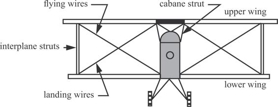
Fig. 6.21 Aerobatics biplane.
Determine the number of turns in the flying wire turnbuckle nF, and the number of turns in the landing wire turnbuckle nL, such that the flying wire tension is 400 lb., and the dihedral is maintained at four degrees. The pitch of the turnbuckle threads is  .
.
Solution. The structural model of the left-hand wing and bracing shown in figure 6.22(a) consists of five truss bars. The turnbuckle displacements are determined from the horizontal position of the wing. Free body diagrams of joints 1 and 4 are shown in figure 6.22(b). A vertical external force Q2 is introduced at joint 1 so that its corresponding displacement q2 can be determined in the application of Castigliano’s theorem. Displacement q2 is specified from the wing’s required dihedral. That is  , and after its determination external force Q2 is set to zero.
From eq. (5.84) on page 136 the complementary energy for a homogenous truss bar subject to a uniform change in temperature is

To account for the displacements of the turnbuckles in Castigliano’s second theorem we modify the axial temperature term in the complementary strain energy. The thermal axial force in the truss bar is obtained from eq. (3.75) on page 43:

Let the thermal strain αΔT be replaced by the initial strain induced by the turnbuckle displacement ΔT = 2np divided by the length of the bar containing the turnbuckle. That is, αΔT→ΔT∕L. Then the complementary strain energy in eq. (a) that includes the displacement caused by the turnbuckle is

where the flexibility influence coefficient  .
.
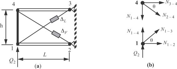
Fig. 6.22 (a) Structural model of the left-hand wing and bracing. (b) Free body diagrams.
The interplane strut subject to force N1 − 4 is assumed to be rigid. Its flexibility influence coefficients vanishes and it does not contribute the elastic complementary strain energy. The complementary strain energy is

The flexibility influence coefficients for the two wing spars is

and the flexibility influence coefficients for the two wires is

Equilibrium equations at joint 1 in figure 6.22(b) are

and equilibrium equations at joint 4 are

The trigonometric functions of the angle θ are

Now eliminate the bar force N1 − 4 between the four equilibrium equations to get the three equations

The force N2 − 4 in the flying wire is taken as the redundant. Solve the remaining bar forces from eq. (j) in terms of the redundant and force Q2 to get

Substitute the results for N1 − 2, N1 − 3, and N3 − 4 from eq. (k) into the complementary strain energy (d) to find the energy in the form  with turnbuckle displacements ΔL and ΔF appearing in Uc as parameters.
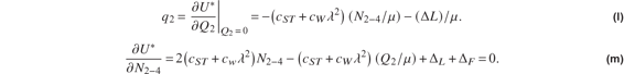
Set  in eq. (l) and solve for the landing wire turnbuckle displacement, followed by solving eq. (m) for the to find flying wire turnbuckle displacement. The results are

Set  to obtain the numerical results for the turnbuckle displacements and their number of turns as

The landing wire turnbuckle decreases the length between joints 1 and 3, and the flying wire turnbuckle increases the length between joints 2 and 4. The bar forces are

■
6.5 References
- Bruhn, E. F., 1973, Analysis and Design of Flight Vehicle Structures, Jacobs Publishing, Inc., Carmel, Indiana, 46032, p. A8.42. (ISBN# 0-9615234-0-9)
- Dowling, Norman E., 1993, Mechanical Behavior of Materials, Prentice Hall, Englewood Cliffs, New Jersey 07632, pp. 245–247.
- Thornton, E. A., 1996, Thermal Structures for Aerospace Applications, AIAA Education Series, American Institute of Aeronautics and Astronautics, Inc., Reston, Virginia, pp. 118–121.
- Warwick, Graham. “Big Fuel Savings Demand New Configurations,” November 7, 2011. Aviation Week.com.
6.6 Practice exercises
1. Each bar in the truss shown in figure 6.23 has a cross-sectional area of 1.0 in.2, and a modulus of elasticity of 107 psi. There is no change in temperature. Use Castigliano’s first theorem to find
a) the horizontal and vertical displacements of joint 1,
b) the stress in psi in each bar, and
c) the horizontal and vertical support reactions at joint 5.
2. The bars in the truss shown in figure 6.24 have the following cross-sectional areas:  ,
,  ,
,  ,
, 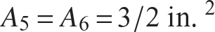 . The modulus of elasticity of each bar is 107 psi. Compute the vertical displacement of the right-hand joint using Castigliano’s second theorem. Note this truss is statically determinate and all bar forces can be determined in terms of external load Q.

Fig. 6.23 Four bar truss of exercise 1.
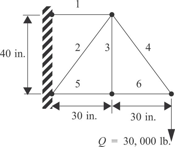
Fig. 6.24 Six-bar truss for exercises 2 and 3.
3. Use Castigliano’s’ second theorem to compute the horizontal displacement of the right-hand joint of exercise 2.
4. The truss shown figure 6.25 consists of three bars: 1-4, 2-4, and 3-4. Each bar has the same cross-sectional area A, modulus of elasticity E, and the same coefficient of thermal expansion α. Bar 1-4 is subjected to a change in temperature ΔT from ambient temperature (the unstressed state), while bars 2-4 and 3-4 remain at ambient temperature. Use Castigliano’s first theorem to determine the horizontal displacement q7 and the vertical displacement q8 of joint 4.
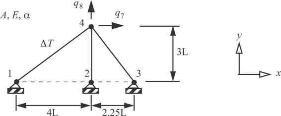
Fig. 6.25 Three-bar truss of exercise 4.
5. The plane truss shown in figure 6.26 represents a single bay of a wing spar truss. For all bars: E = 75GPa and  . The cross-sectional areas of the bars are: 2580 mm2 for the horizontal bars, 387 mm2 for the vertical bars, and 2690 mm2 for the diagonal bars. The upper horizontal bar is heated to 250°C above the zero stress temperature, and all other bars remain at the zero stress temperature. Two 45 kN lift forces act at joints 1 and 2.
Fig. 6.26 Six-bar truss in a single bay of a wing spar.
Use Castigliano’s first theorem to find
a) stiffness matrix in kN/mm,
b) displacement of all joints in mm,
c) all boundary reactions in kN, and
d) the stresses in MPa in each bar.
6. The truss shown in figure 6.27 consists of five bars: 1-2, 1-3, 1-4, 2-4, and 3-4. Each bar has the same cross-sectional area A and same modulus of elasticity E. The lengths of bars 1-2, 1-4, and 3-4 are the same, and are denoted by L. A horizontal force of magnitude P is applied to joint 1. Use Castigliano’s second theorem to determine the horizontal displacement q5 of joint 3.
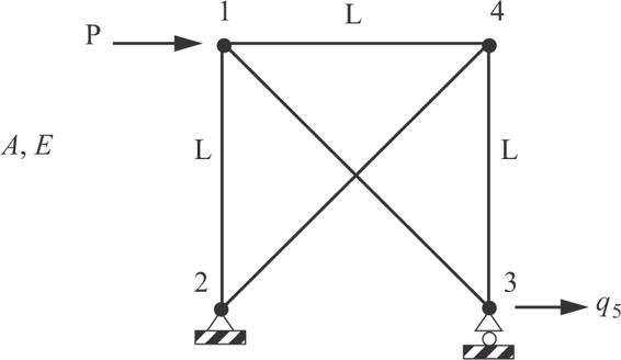
Fig. 6.27 Five-bar truss of exercise 6.
7. A simply supported, uniform beam of length L is subjected to a moment Q1 at its left end as shown in figure 6.28. The material is homogeneous and linear elastic, the cross section is symmetric (Ixy = 0), and there are no thermal strains. The bending stiffness is EI. Use Castigliano’s second theorem to determine the rotation at (a) the left end, and (b) the right end. Neglect energy due to transverse shear deformation.

Fig. 6.28 Simply supported beam of exercise 7.
8. A coplanar frame is subjected to an end force Q1 as shown in figure 6.29. The bars of the frame are uniform with axial stiffness EA and bending stiffness EI. Use Castigliano’s second theorem to find
a) the end rotation q2, and
b) the vertical displacement q3 at the joint.
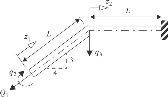
Fig. 6.29 Coplanar frame.
9. Consider the statically indeterminate, uniform beam shown in figure 6.30 that is subjected to a uniform, downward distributed load of intensity p. For small displacements assume that only the complementary strain energy in bending is significant. If the center support moves downward by the amount  and remains attached to the beam, use Castigliano’s second theorem to find the reactions at the left and right supports.
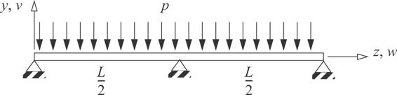
Fig. 6.30 Uniform beam of exercise 9.
10. The frame consists of three slender, uniform bars of length L, and two right angle bends. Assume the bends are rigid joints. Each member has a solid circular cross section of diameter d. A force P acts in the global X-direction at point A. Find the three displacement components  of point A in terms of P, L, d, and E using Castigliano’s second theorem. Assume
  . Neglect deformations due to transverse shear.
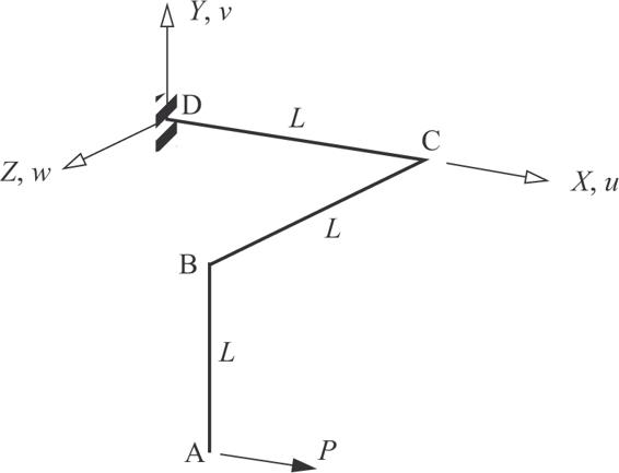
Fig. 6.31 Space frame of exercise 10.
11. The rectangular space truss shown in the sketch consists of six bars: 1-2, 1-3, 1-4, 2-3, 2-4, and 3-4. The cross-sectional area of each bar is 200 mm2. The temperature of bar 2-3 is increased by 30°C above the stress free temperature, while the other five bars remain at the stress free temperature. Calculate the forces in all six bars. The coefficient of thermal expansion  , and the modulus of elasticity
  .
.
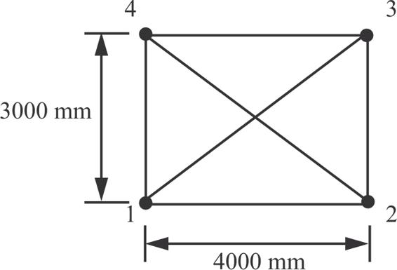
Fig. 6.32 Space truss of exercise 11.
Note that m = 6, j = 4, and r = 0. Hence, 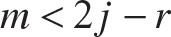 , and this truss cannot support an external load without accelerating. However, under the self-straining caused by the temperature change, it is statically indeterminate internally.
12. Sketch the bending moment diagrams of bars 1-2 and 2-3 in the singly redundant frame shown in figure 6.33. Each bar has the same length L and flexural stiffness EI. Since the bars are slender, neglect deformations due to extension and transverse shear. Take the reaction moment at support point 1 as the redundant.
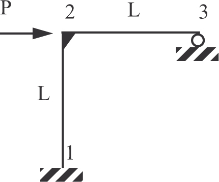
Fig. 6.33 Two-bar frame of exercise 12.
13. The aerodynamic advantages of high aspect-ratio (AR) wings are well known—long span reduces lift-induced drag and narrow chord promotes laminar flow to reduce skin-friction drag. However, a long wing span significantly increases the structural loads at the wing root requiring heaver components to safely transmit the loading to the fuselage. The truss-braced wing (TWB) is a method to reduce the load at the wing root. (It is the subject of research in AOE at Virginia Tech under a NASA program to achieve significant fuel savings for 737 type airplanes (Warwick, 2011)). A simplified model of TWB in this exercise is a single truss bar supporting a wing spar.
A wing spar is clamped at its root and supported by a truss bar that is pinned to the support at one end and pinned to the spar at the other end. Refer to figure 6.34. The spar is subjected to a span-wise distributed air load fy(z) approximated by

where the lift on the wing is denoted by L and the wing span is denoted by b. The pin connection of the truss bar to the spar is at the span-wise distance s·b from the root, where the range of nondimensional parameter s is  .
.
The assemblage is statically indeterminate, and the statically determinate base structure is obtained by removing the lower pin support of the truss bar and replacing it by the redundant force Q which is also the tensile force in the truss bar. Refer to the right-hand sketch in figure 6.34. The condition of compatibility is the displacement corresponding to the redundant is equal to zero. Enforce compatibility by Castigliano’s second theorem given by

where ls is the length of the strut. Numerical data are listed in table 6.7.

Fig. 6.34 Truss-braced wing.
a) Plot the normalized bending moment at the wing root (Mx(0))∕M0 versus s for  , where M0 is the root bending moment of the cantilever wing; i.e.,
b) Plot the tensile normal stress  in the strut versus s for
  .
.
c) If the allowable tensile stress in the strut is 30 ksi, what is the value of s to yield the smallest value of the ratio (Mx(0))∕M0? What is the value of (Mx(0))∕M0 for this particular s?
Table 6.7 Numerical data for the strut-braced wing
|
b, wing span |
390 in. |
|
h, vertical distance from the spar centroid to lower strut support |
72 in. |
|
A, cross-sectional area of the spar |
23.88 in.2 |
|
Ixx, second area moment of the cross section of the spar |
872.716 in.4 |
|
As, cross-sectional area of the strut (1.75 in. diameter) |
2.40528 in.2 |
|
L, wing lift |
50,000. lb. |
|
E, modulus of elasticity for the spar and strut material |
10 × 106 1b./in.2 |