
5.1.5: Aircrafts' cockpits
- Page ID
- 78130

\( \newcommand{\vecs}[1]{\overset { \scriptstyle \rightharpoonup} {\mathbf{#1}} } \)
\( \newcommand{\vecd}[1]{\overset{-\!-\!\rightharpoonup}{\vphantom{a}\smash {#1}}} \)
\( \newcommand{\id}{\mathrm{id}}\) \( \newcommand{\Span}{\mathrm{span}}\)
( \newcommand{\kernel}{\mathrm{null}\,}\) \( \newcommand{\range}{\mathrm{range}\,}\)
\( \newcommand{\RealPart}{\mathrm{Re}}\) \( \newcommand{\ImaginaryPart}{\mathrm{Im}}\)
\( \newcommand{\Argument}{\mathrm{Arg}}\) \( \newcommand{\norm}[1]{\| #1 \|}\)
\( \newcommand{\inner}[2]{\langle #1, #2 \rangle}\)
\( \newcommand{\Span}{\mathrm{span}}\)
\( \newcommand{\id}{\mathrm{id}}\)
\( \newcommand{\Span}{\mathrm{span}}\)
\( \newcommand{\kernel}{\mathrm{null}\,}\)
\( \newcommand{\range}{\mathrm{range}\,}\)
\( \newcommand{\RealPart}{\mathrm{Re}}\)
\( \newcommand{\ImaginaryPart}{\mathrm{Im}}\)
\( \newcommand{\Argument}{\mathrm{Arg}}\)
\( \newcommand{\norm}[1]{\| #1 \|}\)
\( \newcommand{\inner}[2]{\langle #1, #2 \rangle}\)
\( \newcommand{\Span}{\mathrm{span}}\) \( \newcommand{\AA}{\unicode[.8,0]{x212B}}\)
\( \newcommand{\vectorA}[1]{\vec{#1}} % arrow\)
\( \newcommand{\vectorAt}[1]{\vec{\text{#1}}} % arrow\)
\( \newcommand{\vectorB}[1]{\overset { \scriptstyle \rightharpoonup} {\mathbf{#1}} } \)
\( \newcommand{\vectorC}[1]{\textbf{#1}} \)
\( \newcommand{\vectorD}[1]{\overrightarrow{#1}} \)
\( \newcommand{\vectorDt}[1]{\overrightarrow{\text{#1}}} \)
\( \newcommand{\vectE}[1]{\overset{-\!-\!\rightharpoonup}{\vphantom{a}\smash{\mathbf {#1}}}} \)
\( \newcommand{\vecs}[1]{\overset { \scriptstyle \rightharpoonup} {\mathbf{#1}} } \)
\( \newcommand{\vecd}[1]{\overset{-\!-\!\rightharpoonup}{\vphantom{a}\smash {#1}}} \)
\(\newcommand{\avec}{\mathbf a}\) \(\newcommand{\bvec}{\mathbf b}\) \(\newcommand{\cvec}{\mathbf c}\) \(\newcommand{\dvec}{\mathbf d}\) \(\newcommand{\dtil}{\widetilde{\mathbf d}}\) \(\newcommand{\evec}{\mathbf e}\) \(\newcommand{\fvec}{\mathbf f}\) \(\newcommand{\nvec}{\mathbf n}\) \(\newcommand{\pvec}{\mathbf p}\) \(\newcommand{\qvec}{\mathbf q}\) \(\newcommand{\svec}{\mathbf s}\) \(\newcommand{\tvec}{\mathbf t}\) \(\newcommand{\uvec}{\mathbf u}\) \(\newcommand{\vvec}{\mathbf v}\) \(\newcommand{\wvec}{\mathbf w}\) \(\newcommand{\xvec}{\mathbf x}\) \(\newcommand{\yvec}{\mathbf y}\) \(\newcommand{\zvec}{\mathbf z}\) \(\newcommand{\rvec}{\mathbf r}\) \(\newcommand{\mvec}{\mathbf m}\) \(\newcommand{\zerovec}{\mathbf 0}\) \(\newcommand{\onevec}{\mathbf 1}\) \(\newcommand{\real}{\mathbb R}\) \(\newcommand{\twovec}[2]{\left[\begin{array}{r}#1 \\ #2 \end{array}\right]}\) \(\newcommand{\ctwovec}[2]{\left[\begin{array}{c}#1 \\ #2 \end{array}\right]}\) \(\newcommand{\threevec}[3]{\left[\begin{array}{r}#1 \\ #2 \\ #3 \end{array}\right]}\) \(\newcommand{\cthreevec}[3]{\left[\begin{array}{c}#1 \\ #2 \\ #3 \end{array}\right]}\) \(\newcommand{\fourvec}[4]{\left[\begin{array}{r}#1 \\ #2 \\ #3 \\ #4 \end{array}\right]}\) \(\newcommand{\cfourvec}[4]{\left[\begin{array}{c}#1 \\ #2 \\ #3 \\ #4 \end{array}\right]}\) \(\newcommand{\fivevec}[5]{\left[\begin{array}{r}#1 \\ #2 \\ #3 \\ #4 \\ #5 \\ \end{array}\right]}\) \(\newcommand{\cfivevec}[5]{\left[\begin{array}{c}#1 \\ #2 \\ #3 \\ #4 \\ #5 \\ \end{array}\right]}\) \(\newcommand{\mattwo}[4]{\left[\begin{array}{rr}#1 \amp #2 \\ #3 \amp #4 \\ \end{array}\right]}\) \(\newcommand{\laspan}[1]{\text{Span}\{#1\}}\) \(\newcommand{\bcal}{\cal B}\) \(\newcommand{\ccal}{\cal C}\) \(\newcommand{\scal}{\cal S}\) \(\newcommand{\wcal}{\cal W}\) \(\newcommand{\ecal}{\cal E}\) \(\newcommand{\coords}[2]{\left\{#1\right\}_{#2}}\) \(\newcommand{\gray}[1]{\color{gray}{#1}}\) \(\newcommand{\lgray}[1]{\color{lightgray}{#1}}\) \(\newcommand{\rank}{\operatorname{rank}}\) \(\newcommand{\row}{\text{Row}}\) \(\newcommand{\col}{\text{Col}}\) \(\renewcommand{\row}{\text{Row}}\) \(\newcommand{\nul}{\text{Nul}}\) \(\newcommand{\var}{\text{Var}}\) \(\newcommand{\corr}{\text{corr}}\) \(\newcommand{\len}[1]{\left|#1\right|}\) \(\newcommand{\bbar}{\overline{\bvec}}\) \(\newcommand{\bhat}{\widehat{\bvec}}\) \(\newcommand{\bperp}{\bvec^\perp}\) \(\newcommand{\xhat}{\widehat{\xvec}}\) \(\newcommand{\vhat}{\widehat{\vvec}}\) \(\newcommand{\uhat}{\widehat{\uvec}}\) \(\newcommand{\what}{\widehat{\wvec}}\) \(\newcommand{\Sighat}{\widehat{\Sigma}}\) \(\newcommand{\lt}{<}\) \(\newcommand{\gt}{>}\) \(\newcommand{\amp}{&}\) \(\definecolor{fillinmathshade}{gray}{0.9}\)The content of this section is inspired by Wikipedia [6].
A cockpit or flight deck is the area, usually in the nose of an aircraft, from which the cabin crew (pilot and co-pilots) commands the aircraft. Except for some small aircraft, modern cockpits are physically separated from the cabin. The cockpit contains the flight instruments on an instrument panel, and the controls which enable the pilot to fly the aircraft, i.e., the control yoke (also known as a control column) that actuates on the elevator and ailerons4, the pedals that actuates on the rudder, and the throttle level position to adjust thrust.
The layout of cockpits in modern airliners has become largely unified across the industry. The majority of the systems-related actuators (typically some short of switch), are usually located in the ceiling on an overhead panel. These are for instance, actuators for the electric system, fuel system, hydraulic system, and pressurization system. Radio communication systems are generally placed on a panel between the pilot’s seats known as the pedestal. The instrument panel or instrument display is located in front of the pilots, so that all displays are visible. In modern electronic cockpits, the block displays usually regarded as essential are Mode Control Panel (MCP), Primary Flight Display (PFD), Navigation Display (ND), Engine Indicator and Crew Alerting System (EICAS), Flight Management System (FMS), and back-up instruments. Thus, these five elements (together with the back-ups) compose the instrument panel (containing all flight and navigation instruments as electronic displays) in a modern airliner. Notice that mechanical instruments have been substituted by electronic displays, and this is why this discipline is now referred to as avionics systems (the electronics on board the aircraft).
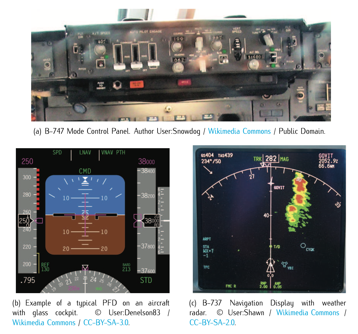
Figure 5.11: Aircraft glass cockpit displays: MCP, PFD, and ND.
Mode Control Panel (MCP): A MCP is an instrument panel that permits cabin crew to control the autopilot and related systems. It is a long narrow panel located centrally in front of the pilot, just above the PFD and rest of displays. The panel covers a long but narrow area usually referred to as the glareshield panel as illustrated in Figure 5.11.a. The MPC contains the elements (mechanical or digital) that allow the cabin crew to select the autopilot mode, i.e., to specify the autopilot to hold a specific altitude, to change altitude at a specific rate, to maintain a specific heading, to turn to a new heading, to follow a route of waypoints, etc., and to engage or disengage the auto-throttle. Thus, it permits activating different levels of automation in flight (from fully automated to fully manual). Notice that MCP is a Boeing designation (that has been informally adopted as a generic name); the same unit with the same functionalities on an Airbus aircraft is referred to as the FCU (Flight Control Unit).
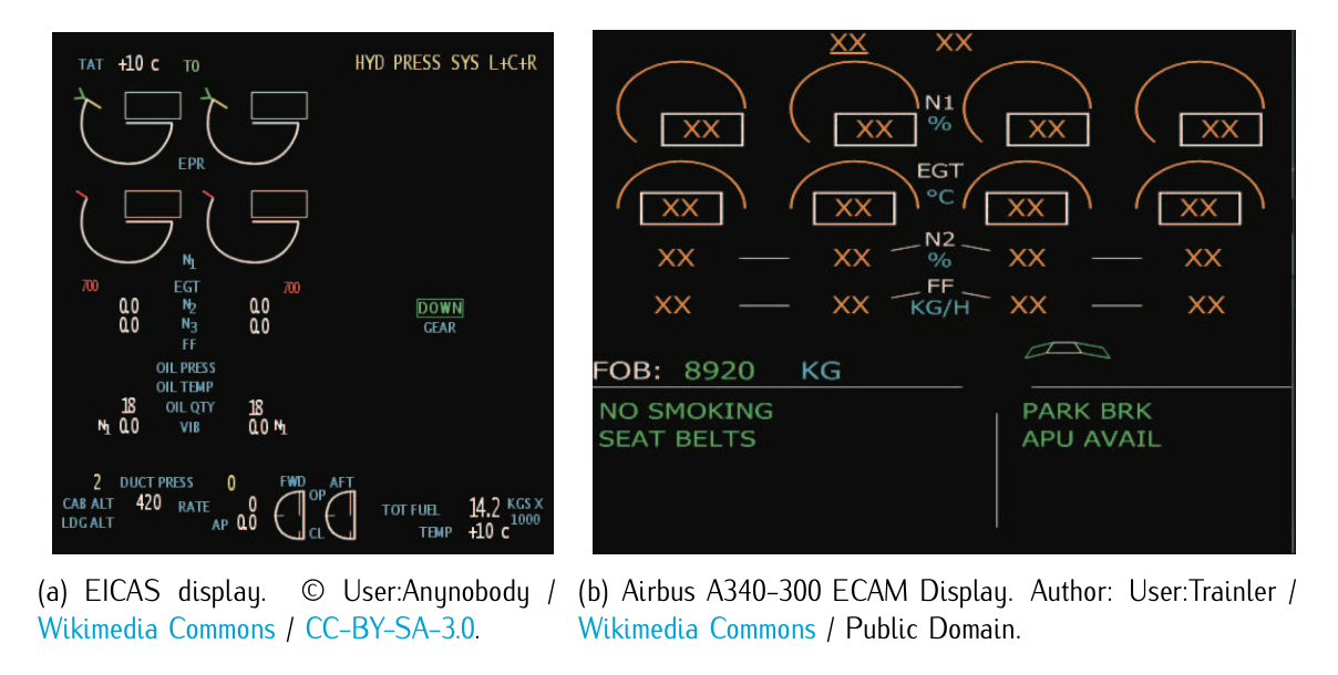
Figure 5.12: EICAS/ECAM cockpit displays.
Primary Flight Display (PFD): The PFD is a modern, electronic based aircraft instrument dedicated to flight information. It combines the older instruments arrangement (T- arrangement or T-arrangement plus turn and slip and variometer) into one compact display, simplifying pilot tasks. It is located in a prominent position, typically centered in the cockpit for direct view. It includes in most cases a digitized presentation of the attitude indicator (artificial horizon), air speed indicator, altitude indicator, and the vertical speed indicator (variometer). Also, it might include some form of heading indicator (directional gyro) and ILS/VOR deviation indicators (CDI). Figure 5.11.b illustrates it.
Navigation Display (ND): The ND is an electronic based aircraft instrument showing the route, information on the next waypoint, current wind speed and wind direction. It can also show meteorological data such as incoming storms, navaids5 located on earth. This electronic display is sometimes referred to as MFD (multi-function display). Figure 5.11.c illustrates how it looks like.
Engine Indication and Crew Alerting System (EICAS) (used by Boeing) or Electronic Centralized Aircraft Monitor (ECAM) (by Airbus): The EICAS/ECAM displays information about the aircraft’s systems, including its fuel, electrical, and propulsion systems (engines). It allows the cabin crew to monitor the following information: values for the different engines, fuel temperature, fuel flow, the electrical system, cockpit or cabin temperature and pressure, control surfaces and so on. The pilot may select display of information by means of button press. The EICAS/ECAM display improves situational awareness by allowing the cabin crew to view complex information in a graphical format and also by alerting the crew to unusual or hazardous situations. For instance, for the EICAS display, if an engine begins to lose oil pressure, an alert sounds, the display switches to the page with the oil system information and outline the low oil pressure data with a red box.
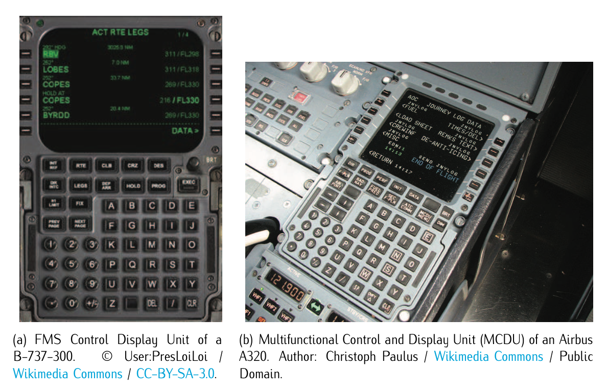
Figure 5.13: Flight Management System (FMS) Control Display Unit.
Flight Management System (FMS): The FMS is a specialized computer system that automates a wide variety of in-flight tasks, reducing the workload on the flight crew. Its primary function is in-flight management of the flight plan6, which is uploaded before departure and updated via data-link communications. Another function of the FMS is to guide the aircraft along the flight plan. This is done by measuring the current state (position, velocity, heading angle, etc.) of the aircraft, comparing them with the desired one, and finally setting a guidance law. From the cockpit, the FMS is normally controlled through a Control Display Unit (CDU) which incorporates a small screen and keyboard or touchscreen. The FMS sends the flight plan for display to the Navigation Display (ND) and other electronic displays in order them to present the following flight plan information: waypoints, altitudes, speeds, bearings, navaids, etc.
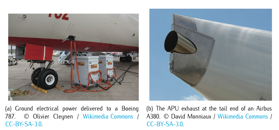
Figure 5.14: Aircraft electrical generation sources: ground unit and APU.
4. An alternative to the yoke in most modern aircraft is the centre stick or side-stick (colloquially known as joystick).
5. navaids refers to navigational aids and will be studied in Chapter 10. It includes VORs, DMEs, ILS, NDB, etc.
6. the flight plan will be studied in Chapter 10.