
10.1.2: History
- Page ID
- 78374

\( \newcommand{\vecs}[1]{\overset { \scriptstyle \rightharpoonup} {\mathbf{#1}} } \)
\( \newcommand{\vecd}[1]{\overset{-\!-\!\rightharpoonup}{\vphantom{a}\smash {#1}}} \)
\( \newcommand{\id}{\mathrm{id}}\) \( \newcommand{\Span}{\mathrm{span}}\)
( \newcommand{\kernel}{\mathrm{null}\,}\) \( \newcommand{\range}{\mathrm{range}\,}\)
\( \newcommand{\RealPart}{\mathrm{Re}}\) \( \newcommand{\ImaginaryPart}{\mathrm{Im}}\)
\( \newcommand{\Argument}{\mathrm{Arg}}\) \( \newcommand{\norm}[1]{\| #1 \|}\)
\( \newcommand{\inner}[2]{\langle #1, #2 \rangle}\)
\( \newcommand{\Span}{\mathrm{span}}\)
\( \newcommand{\id}{\mathrm{id}}\)
\( \newcommand{\Span}{\mathrm{span}}\)
\( \newcommand{\kernel}{\mathrm{null}\,}\)
\( \newcommand{\range}{\mathrm{range}\,}\)
\( \newcommand{\RealPart}{\mathrm{Re}}\)
\( \newcommand{\ImaginaryPart}{\mathrm{Im}}\)
\( \newcommand{\Argument}{\mathrm{Arg}}\)
\( \newcommand{\norm}[1]{\| #1 \|}\)
\( \newcommand{\inner}[2]{\langle #1, #2 \rangle}\)
\( \newcommand{\Span}{\mathrm{span}}\) \( \newcommand{\AA}{\unicode[.8,0]{x212B}}\)
\( \newcommand{\vectorA}[1]{\vec{#1}} % arrow\)
\( \newcommand{\vectorAt}[1]{\vec{\text{#1}}} % arrow\)
\( \newcommand{\vectorB}[1]{\overset { \scriptstyle \rightharpoonup} {\mathbf{#1}} } \)
\( \newcommand{\vectorC}[1]{\textbf{#1}} \)
\( \newcommand{\vectorD}[1]{\overrightarrow{#1}} \)
\( \newcommand{\vectorDt}[1]{\overrightarrow{\text{#1}}} \)
\( \newcommand{\vectE}[1]{\overset{-\!-\!\rightharpoonup}{\vphantom{a}\smash{\mathbf {#1}}}} \)
\( \newcommand{\vecs}[1]{\overset { \scriptstyle \rightharpoonup} {\mathbf{#1}} } \)
\( \newcommand{\vecd}[1]{\overset{-\!-\!\rightharpoonup}{\vphantom{a}\smash {#1}}} \)
\(\newcommand{\avec}{\mathbf a}\) \(\newcommand{\bvec}{\mathbf b}\) \(\newcommand{\cvec}{\mathbf c}\) \(\newcommand{\dvec}{\mathbf d}\) \(\newcommand{\dtil}{\widetilde{\mathbf d}}\) \(\newcommand{\evec}{\mathbf e}\) \(\newcommand{\fvec}{\mathbf f}\) \(\newcommand{\nvec}{\mathbf n}\) \(\newcommand{\pvec}{\mathbf p}\) \(\newcommand{\qvec}{\mathbf q}\) \(\newcommand{\svec}{\mathbf s}\) \(\newcommand{\tvec}{\mathbf t}\) \(\newcommand{\uvec}{\mathbf u}\) \(\newcommand{\vvec}{\mathbf v}\) \(\newcommand{\wvec}{\mathbf w}\) \(\newcommand{\xvec}{\mathbf x}\) \(\newcommand{\yvec}{\mathbf y}\) \(\newcommand{\zvec}{\mathbf z}\) \(\newcommand{\rvec}{\mathbf r}\) \(\newcommand{\mvec}{\mathbf m}\) \(\newcommand{\zerovec}{\mathbf 0}\) \(\newcommand{\onevec}{\mathbf 1}\) \(\newcommand{\real}{\mathbb R}\) \(\newcommand{\twovec}[2]{\left[\begin{array}{r}#1 \\ #2 \end{array}\right]}\) \(\newcommand{\ctwovec}[2]{\left[\begin{array}{c}#1 \\ #2 \end{array}\right]}\) \(\newcommand{\threevec}[3]{\left[\begin{array}{r}#1 \\ #2 \\ #3 \end{array}\right]}\) \(\newcommand{\cthreevec}[3]{\left[\begin{array}{c}#1 \\ #2 \\ #3 \end{array}\right]}\) \(\newcommand{\fourvec}[4]{\left[\begin{array}{r}#1 \\ #2 \\ #3 \\ #4 \end{array}\right]}\) \(\newcommand{\cfourvec}[4]{\left[\begin{array}{c}#1 \\ #2 \\ #3 \\ #4 \end{array}\right]}\) \(\newcommand{\fivevec}[5]{\left[\begin{array}{r}#1 \\ #2 \\ #3 \\ #4 \\ #5 \\ \end{array}\right]}\) \(\newcommand{\cfivevec}[5]{\left[\begin{array}{c}#1 \\ #2 \\ #3 \\ #4 \\ #5 \\ \end{array}\right]}\) \(\newcommand{\mattwo}[4]{\left[\begin{array}{rr}#1 \amp #2 \\ #3 \amp #4 \\ \end{array}\right]}\) \(\newcommand{\laspan}[1]{\text{Span}\{#1\}}\) \(\newcommand{\bcal}{\cal B}\) \(\newcommand{\ccal}{\cal C}\) \(\newcommand{\scal}{\cal S}\) \(\newcommand{\wcal}{\cal W}\) \(\newcommand{\ecal}{\cal E}\) \(\newcommand{\coords}[2]{\left\{#1\right\}_{#2}}\) \(\newcommand{\gray}[1]{\color{gray}{#1}}\) \(\newcommand{\lgray}[1]{\color{lightgray}{#1}}\) \(\newcommand{\rank}{\operatorname{rank}}\) \(\newcommand{\row}{\text{Row}}\) \(\newcommand{\col}{\text{Col}}\) \(\renewcommand{\row}{\text{Row}}\) \(\newcommand{\nul}{\text{Nul}}\) \(\newcommand{\var}{\text{Var}}\) \(\newcommand{\corr}{\text{corr}}\) \(\newcommand{\len}[1]{\left|#1\right|}\) \(\newcommand{\bbar}{\overline{\bvec}}\) \(\newcommand{\bhat}{\widehat{\bvec}}\) \(\newcommand{\bperp}{\bvec^\perp}\) \(\newcommand{\xhat}{\widehat{\xvec}}\) \(\newcommand{\vhat}{\widehat{\vvec}}\) \(\newcommand{\uhat}{\widehat{\uvec}}\) \(\newcommand{\what}{\widehat{\wvec}}\) \(\newcommand{\Sighat}{\widehat{\Sigma}}\) \(\newcommand{\lt}{<}\) \(\newcommand{\gt}{>}\) \(\newcommand{\amp}{&}\) \(\definecolor{fillinmathshade}{gray}{0.9}\)The first navigation techniques at the beginning of the 20th century were rudimentary. The navigation was performed via terrain observation and pilots were provided with maps and compasses to locate the aircraft.
Dead reckoning
Some years later the dead reckoning was introduced. The dead reckoning consists in estimating the future position of the aircraft based on the current position, velocity, and course. Pilots were already provided with anemometers to calculate the airspeed of the aircraft and clock to measure time. The flights were designed based on points (typically references in the terrain), and pilots had to follow the established track.
Obviously, when trying to fly a track from one point to another using dead reckoning, the errors were tremendous. This was due to three main reasons:
- Errors in the used instruments (anemometer, compass, and clock).
- Piloting errors.
- Wind effects.
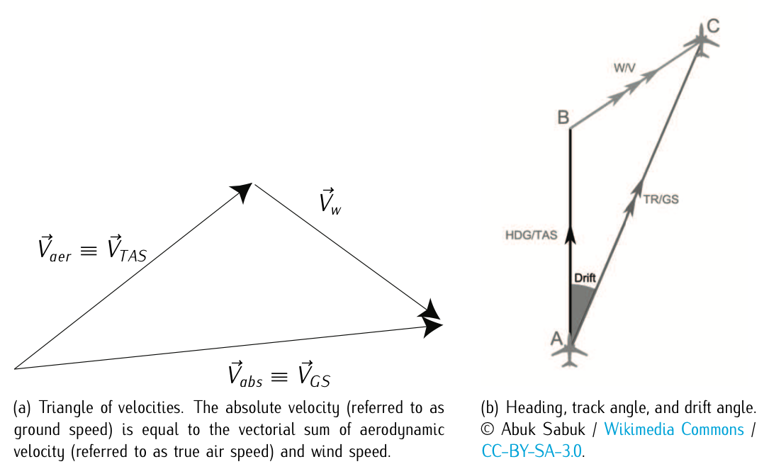
Figure 10.2: Triangle of velocities.
The fist two are inherent to all types of navigation and they will always be to some extent. Nevertheless, errors in instruments are being reduced. Also piloting errors are being minimized due to automatic control systems. One can think that these two errors will converge to some bearable values. On the contrary, wind effects are more relevant, and still play a key role in the uncertainty of aircraft trajectories. Based on these errors, but in particular on wind effects, one can define the triangle of velocities and the track and course angles. See Figure 10.2.
Track angle (TR) (also referred to as course angle): Is the angle between the North (typically magnetic, but the geographic North can be also used) and the absolute velocity of the aircraft and it corresponds with the real track or course the aircraft is flying. The absolute velocity of the aircraft is the sum of the aerodynamic velocity and wind speed: \(\vec{V}_{abs} = \vec{V}_{aer} + \vec{V}_w\). This is called triangle of velocities.
The heading angle (HDG): It is the angle between the North (typically magnetic, but the geographic North can be also used) and the aerodynamic velocity vector. Notice that if we assume symmetric flight, it also coincides with the longitudinal axis of the aircraft. Typically it does not coincide with the track angle since the aircraft might have to compensate cross wind.
For instance, looking at Figure 10.2.b, the aircraft heading is the vector joining A and B, but the real track or course is represented by the vector joining A and C. The corresponding angles would be calculated establishing a reference (typically the magnetic North). Notice that the difference between heading and track is referred to as drift angle.
Some other elements that are important in defining the flight orientation are: the desired track, the cross-track error, and the bearing:
Desired Track (DTR) angle: Is the angle between the north (typically magnetic) and the straight line joining two consecutive waypoints in the flight. Is the track we want to fly, which in ideal conditions would coincide with the track we are actually flying. Unfortunately, this rarely happens.
Cross-Track Error (XTE): Is the distance between the position of the aircraft and the line that represents the desired track. Notice that the distance between a point and a line is the perpendicular to the line passing through the point. Thus XTE = d(DTR,TR), where d can be defined as the norm 2 (the euclidean distance).
Bearing: It is defined as the angle between the north (typically magnetic) and the straight line (in a sphere or ellipsoid would not be exactly straight) connecting the aircraft with a reference point. Note that the bearing depends on the selected reference point. Nowadays, these points typically coincide either with navigational aids located on earth or waypoints calculated based on the information of at least two navigational aids located on earth.
Astronomic navigation
Besides the errors caused by wind effects, dead reckoning navigation had one fundamental drawback: It was required that the selected points acting as a reference were visible by the pilots in any circumstance. As the reader can intuitively imagine, these points were sometimes difficult to identify in case of adverse meteorological conditions (rain, fog, etc.) or at dark during night flights. Moreover, it was really difficult to obtain references over monotone landscapes as it is the case for oceans.
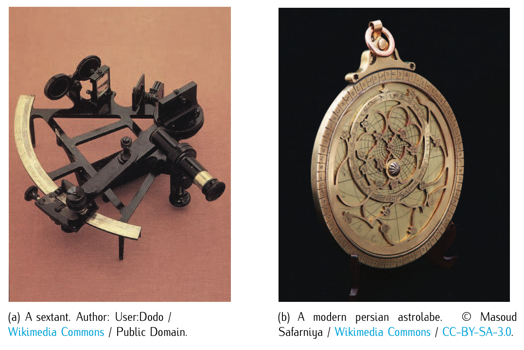
Figure 10.3: Astronomic navigation: sextant and astrolab.
Therefore, pioneer aviators started to use astronomic devices. Devices such as the astrolabe1 and the sextant2 had been used since centuries for maritime navigation. Using these devices, pilots (helped by a man on board that was term navigator) were able to periodically determine the position and minimize errors.
Thanks to this combined type of navigation: the astronomic navigation used together with the dead reckoning navigation, the most important feats among the pioneers were given birth. Thus, in light of history, one can claim that the first oceanic flights in 1919 (Alcock and Brown) and 1929 (Linderbergh) were, in part, thanks to the implementation of the astronomic navigation, which allowed pilots to reach destination without getting lost.
Navigation aids
All the previously described navigation techniques did not require any infrastructure support on the ground, and therefore they can be considered as autonomous navigation techniques. However, such navigation was complicated and required lot of calculations on board. The navigator had to be continuously doing very complicated calculations and this was not operative at all.
As a consequence, there was a necessity of some type of earth-based navigation aids. The first to appear, in 1918, were the so-called aerial beacon (light beacon). This allowed night flight over networked areas, such the USA. However, these aids were limited. In 1919, the radio communications were started to be used. First, installing transmitters in the cockpits to communicate. Afterwards, using the radio-goniometry.3 Radio-goniometers were installed on board and the navigation was performed determining determining the orientation of the aircraft with respect to two transmitter ground-stations which position was known.
Later on, in 1932, the Low Frequency Radio-Range (LFR) appeared, which was the main navigation system used by aircraft for instrument flying in the 1930s and 1940s until the advent of the VHF omnidirectional range (VOR) in the late 1940s. It was used for en route navigation as well as instrumental approaches. Based on a network of radio towers which transmitted directional radio signals, the LFR defined specific airways in the sky. Pilots navigated the LFR by listening to a stream of automated Morse codes. It was some sort of binary codification: hearing a specified tone meant to turn left (in analogy, 1 to turn left) and hearing a different specified tone meant to turn right (in analogy, 0 to turn right).
Since the 40s towards our days, the navigational aids have evolved significantly. To cite a few evolutions, the appearance of VOR and DME in the late 40s-early 50s, the concept of Area Navigation (RNAV) in the late 60s-early 70s, the fully automated ILS approach system in the late 60s, or even the satellite navigation (still to be fully operative) contributed to improve navigation performances. We will not describe them now, since all these types of navigation will be studied later on. As a consequence of the appearance of all these navigation aids throughout the years, nowadays the navigation is mainly performed using instrumental navigation techniques.
Navigation in the presence of other aircraft
Being able to fly, not getting lost, and avoiding terrain obstacles was at the beginning already a big challenge. At the beginning, due to the limited number of aircraft, the navigation did not consider the possibility of encountering other aircraft that might cause a collision. With the appearance of airports, attracting many aircraft to the same physical volume, the concept of navigation shifted immediately to that one of circulation.
Circulation can be defined as the movement to and from or around something. In air navigation, it appeared the necessity of making the aircraft circulate throughout certain structures defined in the air space or following certain rules. To avoid collisions, there were defined some rules based on the capacity of being able to see and to be seen. In the cases of approaches and departures in airports, it appeared the necessity of existence of someone with capability to assign aircraft a sequence to take off. These were the precursors of what we know today as air traffic controllers. In 1935, the first control center for air routes was created in the USA.
The air navigation as a system
As a result, juridic, operative, and technical support frameworks to regulate the air navigation were necessary. The technical and operative frameworks should supply:
- Information system prior departure: related to meteorology, operative limitations, and limitations in the navigation aids.
- Tactical support to pilots: related to possible modifications in the conditions of the flight, specially to avoid potential conflicts with other aircraft or within regions under bad weather conditions.
- Radio-electric infrastructures: to provide aircraft navigation aids.
These three items have constituted the basic pillars in what is referred to as system of air navigation throughout its whole development. The technical and operative framework that conform the system (based on the so-called CNS-ATM4 concept) will be studied in the forthcoming sections.
The juridic framework should take into account the following aspects: formation and licenses of the aeronautical personal; communication systems and procedures; rules about systems and performances on air, and air traffic control; air navigation requirements for aircraft certification, registration and identification for aircraft that carry out international flights; and aeronautical meteorology, maps, and navigation charts; among others. We give know a brief overview of the juridic framework. More in depth analysis will be undertaken in posterior courses regarding air law.
The International regulation (juridic) framework
The very first concern, at the beginning of the 20th century, was that of being able to fly. Within the following 30 years the concern changed to that of being able to fly anywhere (within the possibilities of the aircraft), even though in the presence of adverse navigation conditions, and avoiding collisions with other aircraft and the terrain.
The necessity of flying anywhere (including international flights) encouraged the development of an international regulation framework which could establish the rights and obligations when going beyond the domestic borders. Navigation systems and equipments should be also uniform, so that the crew could maintain the same modus operandi when trespassing borders.
In 1919, the International Commission for Air Navigation (ICAN) was created to provide international regulations. In practice, it was the principal organ of an international arrangement requiring administrative, legislative and judicial agents. At the end World War II, in November 1944, 55 states were invited to Chicago to celebrate a conference the Chicago Convention was signed. The Chicago Convention, as studied in Chapter 8, promoted the safe and orderly development of international civil aviation throughout the world. It set standards and regulations necessary for aviation safety, security, efficiency and regularity, as well as for aviation environmental protection. This obviously included air navigation regulations. The Chicago Convention gave birth to ICAO, successor of ICAN. The development of ICAO’s regulation (see contents of Chicago convention in Chapter 8) has led to the creation of international juridic framework.
In Spain we count with AENA (Aeropuertos Españoles y Navegación Aérea), divided into two main directions: Airports and Air Navigation. Regarding the Air Navigation direction, its main function is to provide aircraft flying in what is termed as civil traffic (commercial flights and general aviation flights) all means so that aircraft are able to navigate and circulate with safety, fluidity, and efficiency over the air space under Spanish responsibility. AENA is therefore the Air Navigation Service Provider (ANSP) in Spain. Also in Spain, the regulator organ is AESA (Agencia Estatal de Seguridad Aérea), which depends of the Dir. General de Aviación Civil, Ministerio de Fomento. AESA is the state body that ensures civil aviation standards in all aeronautical activity in Spain.
If we draw a parallelism, the European Civil Aviation Conference (ECAC) is the European regulator organ and the European Organization for the Safety of Air Navigation (EUROCONTROL) is the ANSP in Europe.5 In the USA, both the function of regulator and ANSP is held by the FAA.
Technical and operative framework
The main goal of air navigation is to make possible air transportation day after day by means of providing the required services to perform operations safely and efficiently. These services are provided based on an organization, human resources, technical means, and a defined modus operandi.
The so constituted system is referred to as CNS-ATM (Communications, Navigation & Surveillance-Air Traffic Management). Therefore, CNS corresponds to the required technical means to fulfill the above mentioned air navigation’s main goal, while ATM refers to the organizational scope and the definition of operational procedures. The CNS will be studied in Chapter 11. ATM is a fundamental part of the so called air navigation services, which is to be studied in the forthcoming sections.
1. An astrolabe is an elaborate inclinometer, historically used by astronomers, navigators, and astrologers. Its many uses include locating and predicting the positions of the Sun, Moon, planets, and stars, determining local time given local latitude and vice-versa.
2. The sextant is an instrument that permits measuring the angles between two objects, such for instance a star or planet and the horizon. Knowing the elevation of the sun the hour of the day, the latitude at which the observer is located can be determined.
3. A goniometer is an instrument that either measures an angle or allows an object to be rotated to a precise angular position.
4. As it will be introduced later on, CNS stands for Communication, Navigation and Surveillance; ATM stands for Air Traffic Management.
5. To be more precise, it is the ANSP in Belgium, Netherlands, Luxembourg, and north-west Germany