
11.3.7: VOR
- Page ID
- 78400

\( \newcommand{\vecs}[1]{\overset { \scriptstyle \rightharpoonup} {\mathbf{#1}} } \)
\( \newcommand{\vecd}[1]{\overset{-\!-\!\rightharpoonup}{\vphantom{a}\smash {#1}}} \)
\( \newcommand{\id}{\mathrm{id}}\) \( \newcommand{\Span}{\mathrm{span}}\)
( \newcommand{\kernel}{\mathrm{null}\,}\) \( \newcommand{\range}{\mathrm{range}\,}\)
\( \newcommand{\RealPart}{\mathrm{Re}}\) \( \newcommand{\ImaginaryPart}{\mathrm{Im}}\)
\( \newcommand{\Argument}{\mathrm{Arg}}\) \( \newcommand{\norm}[1]{\| #1 \|}\)
\( \newcommand{\inner}[2]{\langle #1, #2 \rangle}\)
\( \newcommand{\Span}{\mathrm{span}}\)
\( \newcommand{\id}{\mathrm{id}}\)
\( \newcommand{\Span}{\mathrm{span}}\)
\( \newcommand{\kernel}{\mathrm{null}\,}\)
\( \newcommand{\range}{\mathrm{range}\,}\)
\( \newcommand{\RealPart}{\mathrm{Re}}\)
\( \newcommand{\ImaginaryPart}{\mathrm{Im}}\)
\( \newcommand{\Argument}{\mathrm{Arg}}\)
\( \newcommand{\norm}[1]{\| #1 \|}\)
\( \newcommand{\inner}[2]{\langle #1, #2 \rangle}\)
\( \newcommand{\Span}{\mathrm{span}}\) \( \newcommand{\AA}{\unicode[.8,0]{x212B}}\)
\( \newcommand{\vectorA}[1]{\vec{#1}} % arrow\)
\( \newcommand{\vectorAt}[1]{\vec{\text{#1}}} % arrow\)
\( \newcommand{\vectorB}[1]{\overset { \scriptstyle \rightharpoonup} {\mathbf{#1}} } \)
\( \newcommand{\vectorC}[1]{\textbf{#1}} \)
\( \newcommand{\vectorD}[1]{\overrightarrow{#1}} \)
\( \newcommand{\vectorDt}[1]{\overrightarrow{\text{#1}}} \)
\( \newcommand{\vectE}[1]{\overset{-\!-\!\rightharpoonup}{\vphantom{a}\smash{\mathbf {#1}}}} \)
\( \newcommand{\vecs}[1]{\overset { \scriptstyle \rightharpoonup} {\mathbf{#1}} } \)
\( \newcommand{\vecd}[1]{\overset{-\!-\!\rightharpoonup}{\vphantom{a}\smash {#1}}} \)
\(\newcommand{\avec}{\mathbf a}\) \(\newcommand{\bvec}{\mathbf b}\) \(\newcommand{\cvec}{\mathbf c}\) \(\newcommand{\dvec}{\mathbf d}\) \(\newcommand{\dtil}{\widetilde{\mathbf d}}\) \(\newcommand{\evec}{\mathbf e}\) \(\newcommand{\fvec}{\mathbf f}\) \(\newcommand{\nvec}{\mathbf n}\) \(\newcommand{\pvec}{\mathbf p}\) \(\newcommand{\qvec}{\mathbf q}\) \(\newcommand{\svec}{\mathbf s}\) \(\newcommand{\tvec}{\mathbf t}\) \(\newcommand{\uvec}{\mathbf u}\) \(\newcommand{\vvec}{\mathbf v}\) \(\newcommand{\wvec}{\mathbf w}\) \(\newcommand{\xvec}{\mathbf x}\) \(\newcommand{\yvec}{\mathbf y}\) \(\newcommand{\zvec}{\mathbf z}\) \(\newcommand{\rvec}{\mathbf r}\) \(\newcommand{\mvec}{\mathbf m}\) \(\newcommand{\zerovec}{\mathbf 0}\) \(\newcommand{\onevec}{\mathbf 1}\) \(\newcommand{\real}{\mathbb R}\) \(\newcommand{\twovec}[2]{\left[\begin{array}{r}#1 \\ #2 \end{array}\right]}\) \(\newcommand{\ctwovec}[2]{\left[\begin{array}{c}#1 \\ #2 \end{array}\right]}\) \(\newcommand{\threevec}[3]{\left[\begin{array}{r}#1 \\ #2 \\ #3 \end{array}\right]}\) \(\newcommand{\cthreevec}[3]{\left[\begin{array}{c}#1 \\ #2 \\ #3 \end{array}\right]}\) \(\newcommand{\fourvec}[4]{\left[\begin{array}{r}#1 \\ #2 \\ #3 \\ #4 \end{array}\right]}\) \(\newcommand{\cfourvec}[4]{\left[\begin{array}{c}#1 \\ #2 \\ #3 \\ #4 \end{array}\right]}\) \(\newcommand{\fivevec}[5]{\left[\begin{array}{r}#1 \\ #2 \\ #3 \\ #4 \\ #5 \\ \end{array}\right]}\) \(\newcommand{\cfivevec}[5]{\left[\begin{array}{c}#1 \\ #2 \\ #3 \\ #4 \\ #5 \\ \end{array}\right]}\) \(\newcommand{\mattwo}[4]{\left[\begin{array}{rr}#1 \amp #2 \\ #3 \amp #4 \\ \end{array}\right]}\) \(\newcommand{\laspan}[1]{\text{Span}\{#1\}}\) \(\newcommand{\bcal}{\cal B}\) \(\newcommand{\ccal}{\cal C}\) \(\newcommand{\scal}{\cal S}\) \(\newcommand{\wcal}{\cal W}\) \(\newcommand{\ecal}{\cal E}\) \(\newcommand{\coords}[2]{\left\{#1\right\}_{#2}}\) \(\newcommand{\gray}[1]{\color{gray}{#1}}\) \(\newcommand{\lgray}[1]{\color{lightgray}{#1}}\) \(\newcommand{\rank}{\operatorname{rank}}\) \(\newcommand{\row}{\text{Row}}\) \(\newcommand{\col}{\text{Col}}\) \(\renewcommand{\row}{\text{Row}}\) \(\newcommand{\nul}{\text{Nul}}\) \(\newcommand{\var}{\text{Var}}\) \(\newcommand{\corr}{\text{corr}}\) \(\newcommand{\len}[1]{\left|#1\right|}\) \(\newcommand{\bbar}{\overline{\bvec}}\) \(\newcommand{\bhat}{\widehat{\bvec}}\) \(\newcommand{\bperp}{\bvec^\perp}\) \(\newcommand{\xhat}{\widehat{\xvec}}\) \(\newcommand{\vhat}{\widehat{\vvec}}\) \(\newcommand{\uhat}{\widehat{\uvec}}\) \(\newcommand{\what}{\widehat{\wvec}}\) \(\newcommand{\Sighat}{\widehat{\Sigma}}\) \(\newcommand{\lt}{<}\) \(\newcommand{\gt}{>}\) \(\newcommand{\amp}{&}\) \(\definecolor{fillinmathshade}{gray}{0.9}\)VOR It is a type of short-range radio navigation system, enabling aircraft to determine their position and/or course by receiving VHF radio signals transmitted by a network of fixed ground radio stations. The VOR was developed in the US during World War II and finally deployed by 1946. VORs can be considered all fashioned, but they have played a key role in the development of the modern air navigation. As we pointed out in the case of NDBs, VORs have been traditionally used as intersections along airways, and thus, to configure airways. Many people have been claiming throughout years that the GNSS system will sooner rather than later substitute them (as well as NDBs, DMEs, etc.), but however VORs still play a fundamental role in air navigation. Indeed, VOR is the standard air navigational system in the world, used by both commercial and general aviation.
The way a fix or a direction can be obtained based on VOR information is identical as what have been exposed for NDBs. However, VOR’s signals provide considerably greater accuracy (90 meters approx.) and reliability than NDBs due to a combination of factors. VHF radio is less vulnerable to diffraction (course bending) around terrain features and coastlines. Phase encoding suffers less interference from thunderstorms.
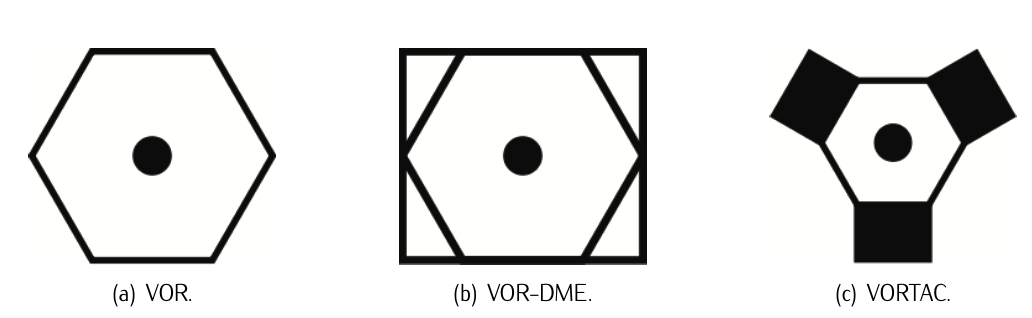
Figure 11.12: VOR (Author: Denelson83 / Wikimedia Commons / Public Domain), VOR- DME (Author: User:mamayer / Wikimedia Commons / / CC0 1.0), and VORTAC (Author: User:Denelson83 / Wikimedia Commons / Public Domain) symbols on a navigation chart.
Typically, VOR stations have co-located DME or military TACAN. A co-located VOR and TACAN is called a VORTAC. A VOR co-located only with DME is called a VOR-DME. A VOR radial with a DME distance allows a one-station position fix. VOR-DMEs and TACANs share the same DME system. The different symbols that identify this co-inhabiting systems are illustrated in Figure 11.12.
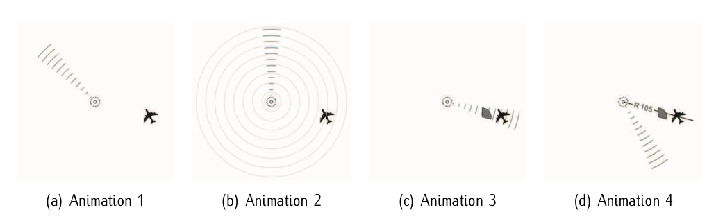
Figure 11.13: Spatial modulation in VORs. A radio beam sweeps (30 times per sec.). When the beam is at the local magnetic north, the station transmits a second, omni-directional signal. The time between the omni-directional signal and instant in which the aircraft receives the directional beam gives the angle from the VOR station (105 deg in this case). © User:Orion 8 / Wikimedia Commons / CC-BY-SA-3.0.
A VOR ground station emits an omnidirectional signal, and a highly directional second signal that varies in phase 30 times a second compared to the omnidirectional one. By comparing the phase of the directional signal to the omnidirectional one, the angle (bearing) formed by the aircraft and the station can be determined. Figure 11.13 illustrates it. This line of position is called the "radial" from the VOR. This bearing is then displayed in the cockpit of the aircraft in one of the following four common types of indicators:
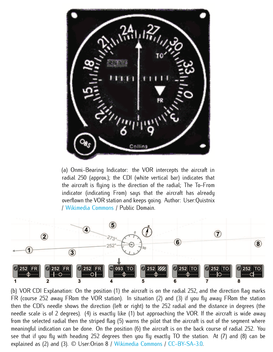
Figure 11.14: VOR displays interpretation.
- Omni-Bearing Indicator (OBI): is the typical light-airplane VOR indicator. It consists of a knob to rotate an "Omni Bearing Selector" (OBS), and the OBS scale around the outside of the instrument, used to set the desired course. A "course deviation indicator" (CDI) is centered when the aircraft is on the selected course, or gives left/right steering commands to return to the course. An ambiguity (TO-FROM) indicator shows whether following the selected course would take the aircraft to, or away from the VOR station. A thorough explanation on how this instrument works is given in Figure 11.14.
- Radio Magnetic Indicator (RMI): features a course arrow superimposed on a rotating card which shows the aircraft’s current heading at the top of the dial. The "tail" of the course arrow points at the current radial from the station, and the "head" of the arrow points at the inverse (180 deg different) course to the station.
- Horizontal Situation Indicator (HSI): is considerably more expensive and complex than a standard VOR indicator, but combines heading information with the navigation display in a much more user-friendly format, approximating a simplified moving map.
- An Area Navigation (RNAV) system is an onboard computer with display and up-to-date navigation database. At least two VOR stations (or one VOR/DME station) is required for the computer to plot aircraft position on a moving map, displaying the course deviation relative to a VOR station or waypoint.
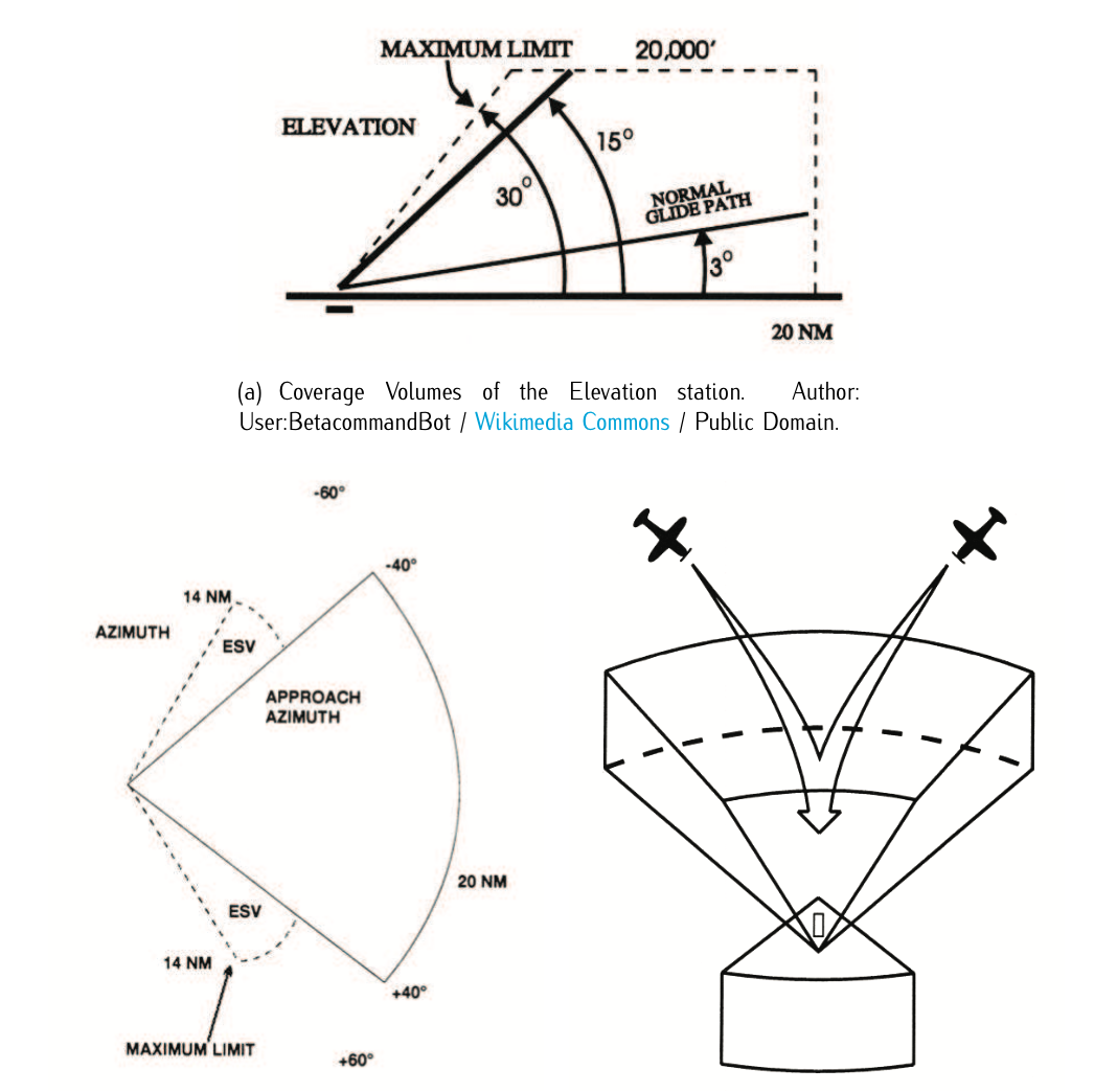
Figure 11.15: MLS coverage.