
1.4: Baling Biomass- Densification and Energy Requirements
- Page ID
- 46841

Shahab Sokhansanj, Ph.D., P.Eng.
University of Saskatchewan
Saskatoon, Saskatchewan, Canada
| Key Terms |
| Field capacity | Bale density | Round baling |
| Material capacity | Bale storage | Square baling |
Variables
Introduction
An important issue in a biomass-based bioenergy system is the transportation of feedstock from the field to the processing facility. Baling, which is the dense packing of biomass into a manageable form, is of importance because it is an energy-consuming process that determines the efficiency of the bioenergy system. Bale density is the most important factor influencing the logistics (number of vehicles, storage volume, duration of use) and cost (labor and energy) of harvesting and delivering biomass to a biorefinery. Unless the biomass is packed to sufficient density, the energy required for transport may exceed the energy release by the bioconversion processes. This chapter discusses two types of balers, round and square; the relationship between biomass density and energy required to make bales; and the pros and cons of the different bale types. The chapter discusses proper methods for handling bales in order to minimize dry matter losses during storage.
Concepts
The contribution of energy and power to the quality of life is indispensable. Countries that enjoy a high quality of life are the ones that consume the most energy per capita. Fuels generate power to run factories, to mobilize motorized transport, and to heat and cool buildings. Until the sixteenth century, most energy came either directly from the sun or indirectly by burning biomass, mostly wood and other plant material. The introduction of coal brought a new era in industrial development. By the nineteenth century, oil and gas revolutionized industrial development.
The development of agriculture happened in parallel with the exploitation of new sources of energy. Farmers abandoned back-breaking farming practices and adopted powered equipment like tractors and cultivators. Farmers who had used hand tools to cut and stack a crop in the field started to use machines that were able to do these tasks more efficiently. Large land preparation equipment, fertilizer applicators, and crop protection equipment, along with new harvest, handling, and transport equipment, were developed. This was possible because of fossil fuel products like gasoline and diesel.
Fossil fuels powered mechanization tools to produce ample food and clothing for humankind to this day. Unfortunately, the use of fossil fuels resulted in some unexpected consequences. The additional carbon dioxide (CO2) and other gases released from fossil fuel combustion increased the concentration of greenhouse gases in the atmosphere impacting or contributing to climate change effects. With time, fossil fuels will become expensive for farmers because of limited availability and policy-based penalties for causing unwanted air polluting emissions. Focus on renewable energy sources as an alternative to displace fossil fuels in society has increased. Biomass, for example, can be used much more efficiently beyond conventional burning as a feedstock for producing biofuels.
The farm equipment manufacturing industry has developed a number of machines for harvesting and post-harvest handling of grains, fruits, and vegetables. Residues such as straws and leaves have traditionally had little financial value, so the industry had not developed many machines to exploit whole crops or residues, instead focusing on extracting only the valuable part of crops, like grain and fruit. The remaining part of the crop such as straw, leaves, and branches were left on the field mostly unused.
Since the late twentieth century, there has been a demand for equipment to collect and package straws, grasses, and whole plants, which coincided with other developments such as restrictions on burning residues (because of air quality) and the operation of conservation tillage systems. The farm equipment industry has developed equipment, such as balers, to gather whole plants, straws, and grasses into round or square packages of much higher density than can be achieved by passive stacking of the material. The dense bales take less space for storing and transporting biomass.
Densification
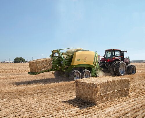
Baling is the most used method for on-farm densifying and packaging of biomass (Figure 1.4.1). Density is the mass of biomass in the bale divided by the volume of the bale:
\[ \rho=\frac{M}{V} \]
where ρ = density (kg/m3)
M = mass of bale (kg)
V = volume of bale (m3)
The density of bales typically varies from 140 to 240 kg/m3 depending on the type of biomass and the pressure used on the biomass when forming the bale. Bale density influences the cost of baling and delivering biomass to the point of its use. Harvesting, storage, transportation, and processing can contribute up to 50% of bioenergy feedstock cost (Shinners and Friede, 2018), so this is an important consideration when operating the system. Transport equipment has a maximum volume and mass (payload) per trailer, so optimizing bale density minimizes transport costs. Creating a dense bale requires power to form the bale and power to transport it during the operation. Bales can be stacked at a location on the farm prior to transport to a bioenergy facility. For energy applications, the dense bales are typically transported to a pelleting facility where the bales are broken and re-compacted into denser pellets.
A range of biomass crops are baled, such as alfalfa (Medicago sativa), timothy (Phleum pretense), grasses in general (Poaceae), wheat (Triticum spp.), maize/corn (Zea mays) and soybean (Glycine max). Biomass crops may be harvested as whole plants (mowed) or separated in the field using a combine harvester that splits the grain from the other plant material. Regardless of the crop, when cut in the field, the material that will be baled is left as a windrow (a low-density linear pile of material parallel to the direction of machine travel). Materials are usually left in the windrow to dry. The ideal moisture content for safe baling and storage depends on the crop but is typically less than 30%. There can be losses due to shattering if the field moisture content is too low, or the equipment must use energy needlessly if too wet. Wet biomass may spoil due to fungal and bacterial growth during storage, which can interfere with refining processes to make biofuels. Depending on the weather, the length of time the plant remains in the field to dry ranges from a few hours to a few days. When ready, a baler picks up the material from the windrow to form bales. Modern balers are mobile, i.e., the equipment moves around the field.
A number of factors determine the choice between round or square bales. Round bales are preferred in wetter regions as they can shed the rain. Square bales are preferred in dry regions as they stack better. In North America, smaller farms tend to use round balers and larger farms tend to use large square balers. Table 1.4.1 lists some characteristics of the balers operating on North American farms. In some countries, such as Ireland, small farmers tend to favor small square bales as they are easier to handle once made.
| Bale Categories | Dimensions (width × depth × length for square; diameter × depth for round) | Mass (kg) | Farm Size | Productivity | Typical Cost ($/h) |
|---|---|---|---|---|---|
|
Small square |
356 × 457 × 914 mm |
24 |
Small farms |
Low |
120 |
|
Large square |
914 × 1219 × 2438 mm |
435 |
Large farms |
High |
250 |
|
Small round |
1219 × 1219 mm |
228 |
Small farms |
Medium |
130 |
|
Large round |
1829 × 1829 mm |
769 |
Large farms |
High |
150 |
Square Baling
A square baler (Figure 1.4.2) consists of a pick-up mechanism (1) to lift the biomass from the windrow and delivers it into feed rolls (2). A set of knives on a rotating wheel (3) cuts the biomass to a set length. A pitman arm (5) connects a flywheel (4) eccentrically (off-center) to a plunger (6). This arrangement converts the rotation of the flywheel into a reciprocating motion, to move the plunger back and forth in the bale chamber.
The power needed to form the bale comes from the tractor power takeoff (PTO). Each rotation plunges biomass as it enters the baling chamber. The reciprocating plunger compresses the loose material to form a bale. The process of feeding hay into the bale chamber and compressing it is repeated until the bale is formed. The density of the bale is determined by adjusting spring-loaded or hydraulic upper and lower tension bars on the bale chamber. A bale-measuring wheel (8) rotates as the bale moves through the bale chamber.
The bale length is controlled by adjusting the number of rotations of the measuring wheel. The tying mechanism (9) is synchronized with the plunger movement. When the plunger is at its rear position and the biomass is fully compressed, a set of needles delivers the twine to the tying mechanism. As the twine is grasped by the tying mechanism, the needles retract, and the bale is tied. Once compressed and tied, the bale is ejected from the bale chamber. Square bales are usually produced in several sizes (Table 1.4.1) and the weight depends upon the baler design, type of biomass, and moisture content, but typically ranges from 24 to 908 kg.
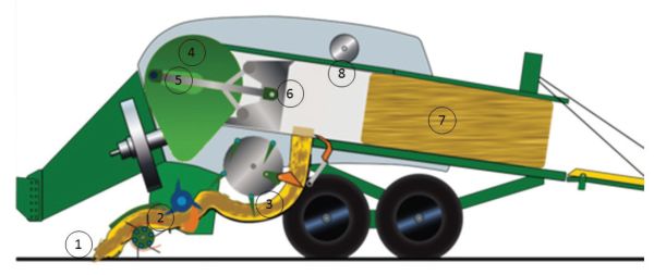

Figure 1.4.3 shows a plot of instantaneous power requirements for a square baler (PAMI, 1990). The peak power requirements are a result of the plunger action. In a typical alfalfa crop, average power input varied from 23 to 30 kW while the instantaneous peak power input was 110 kW. Average drawbar power requirements for towing the baler in the field varied from 5 to 8 kW and peaked at 20 kW in soft or hilly fields. To fully utilize baler capacity, PAMI (1990) recommends a tractor with a minimum PTO rating of 68 kW (90 hp). A tractor with an 83 kW (110 hp) PTO rating would be required in hilly conditions.
Round Baling
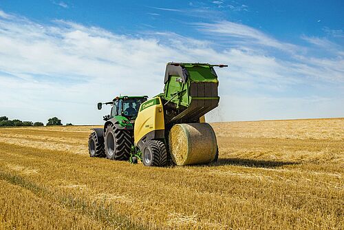
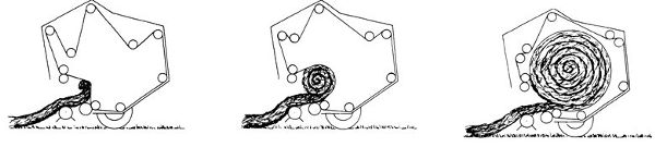
A round baler (Figure 1.4.4) forms the biomass into a cylindrical bale. The round baler collects the biomass from the windrow using finger-like teeth, made from spring steel or a strong polyethylene material, and rolls the biomass inside the bale chamber using wide rollers or belts.
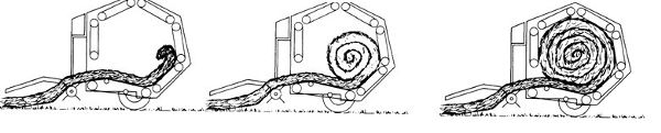
A round baler comes in two types. Those with a fixed-size chamber use fixed position rollers (Figure 1.4.5a), and those with a variable chamber use flexible belts (Figure 1.4.5b). A fixed chamber makes bales with a soft core. A variable chamber makes bales with a hard core. A soft-core bale is “breathable,” meaning the porosity is sufficient for the bale to continue drying when left in the field. The bale size remains fixed by the size of the chamber. In a variable chamber, a series of springs and retractable levers ensures a tight bale is formed from core to circumference. The operator sets the diameter of the bale and a target mass to achieve a required density. Following the formation of the bale, the forward motion of the machine and the inflow of biomass are stopped. Twine or a net is wrapped around the circumference of the bale using a moveable arm. Once the net has encircled the bale enough times to maintain shape and sufficiently contain the material, the arms return to the start position and the twine or net strands are cut. The net wrap covers more of the surface area of the bale, preventing material loss and easily maintaining the shape of the bale.
Once the bale is formed and wrapped, it is ejected from the bale chamber. Some round balers have hydraulic “kickers,” while others are spring loaded or rely on the spinning of the bale to roll the bale out of the chamber. Once the bale has been ejected from the baler, the back door to the chamber is closed, and the machine starts moving forward, taking in biomass until the next bale is ready. Variable-chamber, large round balers typically produce bales from 1.2 to 1.8 m diameter and up to 1.5 m width, weighing from 500 to 1000 kg, depending upon size, material, and moisture content. A typical round bale density ranges from 140 kg/m3 to 180 kg/m3.
(a) Fixed chamber configuration
(b) Variable chamber configuration
Figure \(\PageIndex{5}\): The two types of round balers, (a) fixed chamber and (b) variable chamber (Freeland and Bledsoe, 1988).
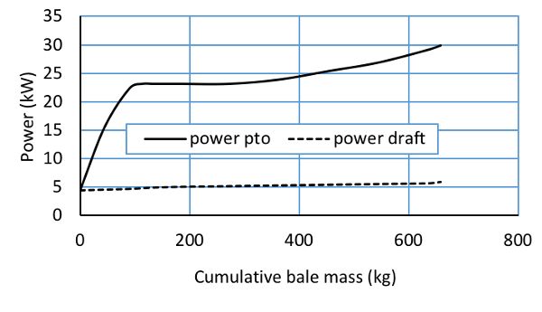
Figure 1.4.6 shows typical PTO and drawbar power requirements for the John Deere 535 round baler at a material capacity of 16.1 t/h (PAMI, 1992). The instantaneous power recorded by the tractor is plotted against the bale weight to show the increase in power input while each bale is formed. The curves are an average of the highly fluctuating measured PTO data, which varied from 5 to 8 kW at no load to a maximum of 32 kW in alfalfa for full sized bales. PTO power input is highly dependent on material capacity (t/h). Drawbar power requirements at 11.5 km/h were about 8 kW when the bale reached to a full size. Although maximum horsepower requirements did not exceed 38 kW, additional power was required to suit other field conditions such as soft and hilly fields. The manufacturer suggested a 56 kW (75 hp) tractor to fully utilize baler capacity.
Assessing Baling Performance
ASABE Standards EP496 and D497 (ASABE Standards, 2015a,b) define the performance of field equipment in terms of field capacity and material capacity.
Field Capacity
Field capacity quantifies the rate of land processed (area per unit time) as:
\[ C_{a}=\frac{SWE_{f}}{10} \]
where Ca = field area covered per unit of time (ha/h)
S = average field speed of the equipment while harvesting (km/h)
W = effective width (m)
Ef = field efficiency (decimal) (Table 1.4.2)
Field speed, S, can range from 4 to 13 km/h (Table 1.4.2). This range represents the variability in field conditions that affects the travelling speed of the equipment.
Effective width, W, is the width over which the machine works. It may be wider or narrower than the measured width of the machine depending on design, how the machine is used in the field with other equipment, and operator experience and skill. The effective width might be determined by the cut width of a mower ahead of the baler, when a wheel rake gathers the mowed crop into a swath for the baler to pick up.
Field efficiency, Ef (Table 1.4.2), is the ratio of the productivity of a machine under field conditions and the theoretical maximum productivity. Field efficiency accounts for failure to utilize the theoretical operating width of the machine, time lost because of operator’s lack of skill, frequent stoppages, and field characteristics that cause interruptions in regular operation. Travel to and from a field, major repairs, preventive maintenance, and daily service activities are not included in field time or field efficiency calculations.
Field efficiency is not a constant for a particular machine but varies with the size and shape of the field, pattern of field operation, crop yield, crop moisture, and other conditions. The majority of time lost in the field is due to turning and idle travel, material handling time, cleaning of clogged equipment, machine adjustment, lubrication, and refueling. Round balers have a lower efficiency than square balers because the shape of the round bale makes handling, transportation, and storage of the bale inefficient compared to handling a square bale (Kemmerer and Liu, 2011).
| Biomass Harvest Equipment | Field Efficiency | Field speed | Remarks | ||
|---|---|---|---|---|---|
| Range (%) | Typical (%) | Range (km/h) | Typical (km/h) | ||
|
Small square baler |
60–85 |
75 |
4.0–10.0 |
6.5 |
Small to mid-size bales |
|
Large square baler |
70–90 |
80 |
6.5–13.0 |
8.0 |
Mid-size to large bales |
|
Large round baler |
55–75 |
65 |
5.0–13.0 |
8.0 |
Commercial round bales |
Material Capacity
Material capacity is the mass of crop baled per hour, and is calculated using the field capacity (Ca) and the field yield:
\[ C_{m}=C_{a}Y \]
where Cm = material capacity (t/h)
Y = average yield of the field (t/ha); it is the amount of biomass that is cut and placed in the swath ready for baling, not the total above-ground biomass in the field.
For crops grown for energy supply purposes, typically no more than 50% of the above ground biomass is cut and baled. In practice, yield (Y) may be as low as 25–30% of the total above ground biomass. The remaining 70–75% of the biomass is left in the field for soil conservation purposes. Removal of a higher percentage may also pick up undesired dirt and foreign material along with the biomass.
Energy Requirements
The bale density that can be achieved is dependent on the specifications of the machine (its dimensions and efficiency) and the mechanical energy that can be supplied to the baler.
Energy Requirements for Square Bales
We start from defining pressure and density in order to calculate energy and power input to make a square bale.
Pressure, P, is calculated using force over area,
\[ P = F/A \]
where A = area on which the force is exerted (m2)
\(f= \text{force (kN)}\)
Force (kN) is derived from mass (M, kg),
\[ F= M (\text{kg}/1000) \times g \ (\text{m/}s^{2}) \]
where g = acceleration due to gravity (9.81 m/s2).
The power requirement is related to bale density. The relationship is determined by first relating pressure to density, then calculating energy from force vs. displacement, and finally estimating power from the time rate of energy.
For the first step, a commonly used equation to relate pressure and density is (Van Pelt, 2003; Afzalinia and Roberge, 2013):
\[ P = (\frac{1}{k} \rho)^{1/n} \ \ \ _{k,n \ > \ 0} \]
| Biomass crop | k | n |
|---|---|---|
|
Stover |
29.48 |
0.330 |
|
Wheat straw |
38.79 |
0.293 |
|
Switchgrass |
100.99 |
0.137 |
where P = the pressure exerted by the plunger (kPa)
k and n = positive constants
\( \rho = \text{density (kg/}m^{3}) \)
Hofstetter and Liu (2011) suggested values for k and n for several crops (Table 1.4.3).
During bale formation, the initial density is zero (empty chamber), and steadily increases to the maximum density possible given the plunger pressure.
The next step is to calculate energy from force and displacement. The total energy input required to make a bale is calculated by integrating the area under the pressure-displacement curve from 0 to Pmax. This integration yields energy input per unit mass (E) for a single stroke of the plunger to form what is known as a wafer. Equation 1.4.7 represents integration of force vs. displacement:
\[ E= \int_{0}^{P_{max}} (\frac{1}{\rho})dP \]
where P = pressure (kN/m2)
E = energy input per unit mass (kJ/kg)
Substituting ρ from Equation 1.4.6 and integrating yields:
\[ E= \frac{1}{(1-n)k}P_{max}^{(-n+1)} \]
Replacing Pmax with ρmax allows an estimate of specific energy, E (kJ/kg):
\[ E=\frac{1}{(1-n)k}(\frac{1}{k}\rho_{max} \ ^{\frac{1-n}{n}}) \]
When making a square bale, each stroke of the plunger makes a wafer of around 51 mm thickness. It would require around 19 strokes to make a 915 mm bale. For a complete bale the energy required, (Eop, kJ), can be calculated from E multiplied by the final mass of the bale,
\[ E_{op} = E \times M \]
For the last step, the power (energy per unit time) required to make one bale is calculated by multiplying the specific energy (E) by the material capacity (Cm)
\[ P_{opt}=\frac{C_{m}E_{op}}{3.6e} \]
where Popt = theoretical power to operate the square baler (kW)
e = efficiency factor that accounts for inefficiency of transmission of power from the PTO to the baler
In practice, ASABE Standard D497 (ASABE Standards, 2015a) suggests that about 4 kW is needed for a baler to run empty so this power overhead must be added to Popt.
Energy Requirements for Round Bales
For a round baler, ASABE Engineering Practice EP 496 (ASABE Standards, 2015b) recommends estimating the operating power for balers and other rotating machines using:
\[ P_{op}=a+bW+cF_{w} \]
where Pop = power-takeoff required to operate the round baler (kW)
W = working width of the baler (m)
Fw = material feed rate, wet mass (t/h)
a, b, and c = machine-specific parameters (Table 1.4.4)
| Baler Type | a (kW) | b (kW/m)* | c (kWh/t) |
|---|---|---|---|
|
Small square |
2.0 |
0 |
1.0 |
|
Large square |
4.0 |
0 |
1.3 |
|
Large round, variable chamber |
4.0 |
0 |
1.1 |
|
Large round, fixed chamber |
2.5 |
0 |
1.8 |
|
* Non-zero values are reported for machinery such as mowers and rakes. |
|||
Comparing the power requirements, Tremblay et al. (1997) found that the variable chamber baler required an average PTO power of 10.2 kW compared to a fixed chamber baler that required an average PTO power of 13.3 kW. Also, the peak PTO power required was considerably less for the variable chamber (14.5 kW) compared to fixed chamber (37.5 kW). This means a much larger tractor would normally be required to operate a fixed chamber baler. For flexible operation in terms of tractor required and size and density of bales, a flexible chamber round baler is perhaps the best option.
Energy Requirements for Pulling a Baler
The power required to drive the tractor and tow the baler is determined from the draft force (D, kN):
\[ D=r\ m\ g\ /\ 1000 \]
where r = ratio, resistance to travel
m = mass of pulled equipment and its load (kg)
g = gravitational acceleration constant = 9.81 m/s2
Resistance to travel is an additional draft force that must be included in computing power requirements. Values of resistance to travel depend on transport wheel dimensions, tire pressure, soil type, and soil moisture. Motion resistance ratios are defined in ASAE S296 (ASABE Standards, 2018). The value of r can be estimated using (ASABE Standards, 2015a):
| Surface Condition | Bn | sl | Drawbar Xd[a] |
|---|---|---|---|
|
Hard—concrete |
80 |
0.04–0.08 |
0.88 |
|
Firm soil |
55 |
0.08–0.10 |
0.77 |
|
Tilled soil |
40 |
0.11–0.13 |
0.75 |
|
Soft soil |
20 |
0.14–0.16 |
0.70 |
|
[a] Xd represents the ratio of draft power to PTO power. The listed values are for 4-wheel drive tractors. |
|||
\[ r=\frac{1}{B_{n}}+0.04+\frac{0.5sl}{\sqrt{B_{n}}} \]
where Bn = soil index factor (Table 1.4.5)
sl = decimal value representing tractor wheel slippage (Table 1.4.5)
Given the speed and draft force (kN), draft power is calculated by:
\[ P_{d}=\frac{DS}{3.6} \]
where Pd = the tractor draft (pull) power (kW)
S = the average forward speed of the baler (km/h)
Applications
Handling and Storing Bales
Bale Stacking
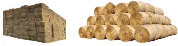
Once the bales are made, they must be removed from the field before the land can be prepared for the next crop. Tractors and loaders equipped with grabbing devices pick up and load the bales onto a trailer for transport out of the field. The bales are then stacked either next to the field or in a central storage site by using a tractor or a loader. HSE (2012) recommends building stacks on firm, dry, level, freely draining ground, which should be open and well ventilated, away from overhead electric poles. Use of stones or crushed rock on the ground beneath a stack to make it level and to stop water rising into the stack is recommended. The site should be away from any potential fire hazards and sources of ignition with good road access so bales can be transported to and from the stack safely. There must be sufficient space to allow tractors, trailers and other vehicles adequate room to maneuver.
Figure 1.4.7 shows the correct configuration of stacking square bales and round bales, with a wide base that narrows as the stack gets higher. The maximum height of the stack should not be greater than 1.5 times the width of the base. Generally, a stack of no more than 10 bales on hard surfaces and 8 bales on soft surfaces is recommended. Square bales must be laid with each row is offset from the row below, such that there is no continuous gap between them. Round bales are stacked in a pyramid with fewer bales in each direction than in the layer below. The outside round bales need a chock at each of the bales in the lowest layer to prevent them from rolling out (Figure 1.4.7). As with square bales, round bales should be laid to cover the gap between two bales underneath.
Once a stack is formed, the weight of each bale becomes an issue for the stability of the pile. The weight of a large bale may range from 300 kg to more than 500 kg. The bales at the top press onto the lower bales causing their slow deformation. The degree of deformation depends upon bale density and moisture content, and the length of time they remain in the stack. A lower density and a higher moisture bale tends to deform more than a higher density and a dryer bale.
Dry Matter Loss
Moisture content at the time of baling plays an important role in the amount of dry matter loss that may happen during baling and later during storage. For leafy biomass like alfalfa, the recommended moisture content for baling is less than 30% and for storage less than 15% to 20%; however, for longer storage, a lower moisture content of 10% to 12% is preferred. Square bales tend to lose less moisture than round bales, but regardless of shape, it is important to make bales as near to the target moisture as possible.
Losses can be mechanical and microbial. Mechanical losses mostly occur during bale handling, such as building the stack or removing the bales from the stack. Some physical removal of biomass (known as leaching) may also take place due to rain wash. Also, the carbohydrates in freshly cut green biomass can decay to CO2, water, and heat.
The most prevalent dry matter loss is due to microbial activity, which causes the deterioration of the plant material and loss of dry matter. The growth of microbes on the biomass is directly related to the moisture content. Dry biomass adsorbs moisture from rain when exposed and becomes a host for mold to develop. Cover and duration of storage both influence dry matter loss (Table 1.4.6). For example, the dry matter loss from an uncovered bale on the ground may range from 5% to 20% within 9 months of storage. If storage time increases to 12 to 18 months, dry matter loss can increase to 20% to 35% of the mass of the bales. Storing bales under a roof will limit losses to 2% to 5%. Research shows there is not much difference between dry matter loss for round bales vs. square bales when stored in similar conditions (Wilcke et al., 2018).
| Storage Method | Storage Period (months) | ||
|---|---|---|---|
| 0 to 9 | 12 to 18 | ||
|
Ground |
Covered with a tarp |
5–9 |
10–15 |
|
Exposed |
5–20 |
20–35 |
|
|
Elevated |
Covered with a tarp |
2–4 |
5–10 |
|
Exposed |
3–15 |
12–35 |
|
|
Barn |
Enclosed |
~2 |
2–5 |
|
Open sides |
2–5 |
3–10 |
|
The range of dry matter loss (Table 1.4.6) stems from differences in climate, crop type, and initial moisture content of the biomass. Nevertheless, these numbers are good for making a decision on the kind of storage system to be chosen for bales. In terms of capital expenditure, storing on the ground is the least expensive and storing in an enclosed barn is the most expensive.
Decision Factors for Square vs. Round Bales
The selection of round or square bales depends on several factors including crop species to be baled, regional climate conditions, volume of crop to be harvested, types of storage available, tractor power, and ancillary services available. Key advantages and disadvantages for round and square bales are listed in Table 1.4.7.
Examples
| Square Bale | Round Bale |
|---|---|
| Advantages | Advantages |
|
• More efficiently uses space in transport and storage • Better shape retention during storage • Easier to stack |
• Greater availability of balers and handling equipment • Lower price for balers • Greater ability to shed water if bales are stored uncovered |
| Disadvantages | Disadvantages |
|
• Greater moisture absorption by bales stored without cover |
• Less efficient use of space in hauling and storing bales • A tendency for bales to lose their shape during storage |
Example \(\PageIndex{1}\)
Example 1: Field and material capacity
Problem:
A field of hay is cut by using a disk mower cutting 5 m swaths. Following a few days of drying, a rotary rake is used to windrow the hay for baling. Calculate the field capacity and material capacity of three balers: small square, large square, and round for a yield of 7 t/ha of hay. Which machine would you choose?
Solution
The effective width is 5 m as this is the swath width of the mower. Calculate field capacity using Equation 1.4.2 and material capacity using Equation 1.4.3:
\( C_{a}=\frac{SWE_{f}}{10} \) (Equation \(\PageIndex{2}\))
\( C_{m}=C_{a}Y \) (Equation \(\PageIndex{3}\))
where Ca = field area covered per unit of time (ha/h)
S = average field speed of the equipment while harvesting (km/h)
W = effective width (m)
Ef = field efficiency (decimal)
Cm = material capacity (t/h)
Y = average yield of the field (t/ha)
Use typical values from Table 1.4.2 for speed and efficiency of each type of baler. Table 1.4.8 lists the input values and calculation results for field capacity and material capacity. The large square baler can process the largest area per hour, therefore it can also process the greatest mass per hour. Thus, with typical values for speed and efficiency, the large square baler would be selected if the only criteria were field and material capacity.
| Baler | Width of cut, W (m) |
Field speed, S (km/h) |
Field efficiency, Ef (%) |
Field capacity, Ca (ha/h) |
Yield, Y (t/ha) |
Material capacity, Cm (t/h) |
|---|---|---|---|---|---|---|
|
Small square baler |
5 |
6.5 |
75 |
2.44 |
7 |
17.06 |
|
Large square baler |
5 |
8.0 |
80 |
3.20 |
7 |
22.40 |
|
Round baler |
5 |
8.0 |
65 |
2.60 |
7 |
18.20 |
Example \(\PageIndex{2}\)
Example 2: Maximum bale density and mass
Problem:
A farmer is making square bales of cornstalk at 35% moisture content (wet mass basis). The compressed bale dimensions are 914 mm × 1219 mm × 2438 mm. Determine the maximum density and mass of each bale given the mass equivalent of force exerted on the cross section (914 mm × 1219 mm) bale is 20 tonne (t).
Solution
The maximum density is a function of the maximum pressure exerted on the pressure exerted on the bale cross section. First, calculate the force on the cross section of the bale (Equation 1.4.5) using the given mass equivalent of force as 20 t, which is 20,000 kg, and acceleration due to gravity as 9.8 m/s2:
\( F= M\ (\text{kg/1000)} \times g\ (\text{m}/s^{2}) \) (Equation \(\PageIndex{5}\))
\( F= 20000 \times 9.8/1000 = 196 \text{ kN} \)
Calculate the pressure exerted on the bale cross section using Equation 1.4.4:
\( P=F/A \) (Equation \(\PageIndex{4}\))
\( P= 196 \text{ kN}/ (0.914 \times 1.219 \ m^{2}) = 175.92 \text{ kPa} \)
Calculate bale density by solving Equation 1.4.6 for ρ, using values of k and n from Table 1.4.3:
\( P_{max} = (\frac{1}{k}\rho)^{1/n} \ _{k,n \ >\ 0} \) (Equation \(\PageIndex{6}\))
\( \rho=kP^{n}=29.48(175.92)^{0.33}=162.1 \text{kg/}m^{3} \)
The mass of the bale can be calculated from density and the dimensions of the bale:
\( M = \rho V = 162.1 \text{ kg/}m^{3} \times (0.914 \times 1.219 \times 2.438 m^{3}) = 440.32 \text{kg} \)
Example \(\PageIndex{3}\)
Example 3: Specific and operating energy
Problem:
For the baler specified in Example 1.4.2, calculate specific energy of the baler and, from this, the operating energy required to make one bale.
Solution
Calculate specific energy using Equation 1.4.9:
\( E = \frac{1}{(1-n)k}(\frac{1}{k}\rho_{max}\ ^\frac{1-n}{n}) \) (Equation \(\PageIndex{9}\))
\( = \frac{1}{(1-0.33)29.48}(\frac{162.36}{29.48}) ^\frac{1-0.33}{0.33} \)
Now, calculate the operating energy using Equation 1.4.10:
\( E_{op}=E\times M \) (Equation \(\PageIndex{10}\))
\( E_{op}= 1.62 \text{ kJ/kg} = 713.32 \text{ kJ} \)
Example \(\PageIndex{4}\)
Example 4: Operating power
Problem:
For the baler in Examples 1.4.2 and 1.4.3, power transmission from the tractor PTO to the baler will not be 100% efficient. Assuming 50% transmission efficiency of power from the tractor to the baler, estimate the operating power that must be supplied to the baler.
Solution
Estimate the theoretical operating power, Popt, using Equation 1.4.11, with e = 0.50:
\( P_{opt}=\frac{C_{m}E_{op}}{3.6e} \) Equation \(\PageIndex{11}\))
\( P_{opt}=\frac{(22,400 \text{ kg/h}) \times 1.62 \text{ kJ/kg}}{(3600 \text{ s/h})(0.50)} = 20.16 \text{ kW} \)
Applying the ASABE D497 assertion that about 4 kW is needed for the machine to run when empty, the Popt is:
\( P_{opt}= 20.16+4=24.16 \text{ kW} \)
Example \(\PageIndex{5}\)
Example 5: Power requirements of a round baler
Problem:
A farmer has the option of using a round baler with a fixed chamber, an operating width of 2 m, a feed intake of 18.2 t/h, and a mass of 15,800 kg, that produces bales of 1.83 m diameter, 1.83 m width or depth, and 180 kg/m3 density. Calculate (a) the power requirement for the fixed chamber round baler, (b) the draft force of the machine, and (c) the draft power of the tractor required to pull the machine through the field.
Solution
- (a) Equation 1.4.12 can be used to estimate the power requirement. A bale of almost 2 m wide would be regarded as a large bale (Table 1.4.1), so the parameters for Equation 1.4.12 can be taken from Table 1.4.4 accordingly:
\( P_{opt}= a+bW+cF \) (Equation \(\PageIndex{12}\))
\( P_{opt}= 2.5+(0 \times 2)+(1.8 \times18.2)= 35.26 \text{kW} \)
- (b) The draft force of the machine can be calculated using Equation 1.4.13:
\( D = r\ m\ g / 1000 \) (Equation \(\PageIndex{13}\))
- First, calculate the motion resistance, r, using Equation 1.4.14 with values from Table 1.4.5. Assume the machine is working on a soft soil surface and with average slippage. Thus, from Table 1.4.5, Bn = 20, sl = 0.15 (average of 0.14 and 0.16):
\( =\frac{1}{B_{n}}+0.04+\frac{0.5sl}{\sqrt{B_{n}}} \) (Equation \(\PageIndex{14}\))
\( r=\frac{1}{20}+0.04+\frac{0.5(0.15)}{\sqrt{20}} = 0.16771 \)
- Next, calculate the mass of bale plus baler:
- Bale volume: V = π r2 L = 3.14 (0.915 m)2 (1.83 m) = 4.814 m3
- Bale mass: M = V ρ = 4.814 m3 × 180 kg/m3 = 866.5 kg
- Mass of bale plus baler: m = 866.5 + 15,800 = 16,666.5 kg
- Substituting values in Equation 1.4.13 yields the draft force of the baler:
\( D = r\ m\ g\ / 1000 = (0.16771 \times 16,666.5 \times 9.81) /1000 = 27.4 \text{ kN} \)
- (c) From the draft force, calculate the draft power, Pd, for the given speed, S, using Equation 1.4.15:
\( P_{d}=\frac{D(\text{kN})S(\frac{km}{h})}{3.6} \) Equation \(\PageIndex{15}\))
\( P_{d}=\frac{27.4(\text{kN})8(\frac{km}{h})}{3.6} = 60.89 \text{ kW} \)
Example \(\PageIndex{6}\)
Example 6: Dry matter loss
Problem:
A stack of round bales from Example 1.4.5 are to be stored with an average moisture content of 15% (wet mass basis). Estimate the dry matter loss from the bales when covered with tarp and stored on the ground for 9 months and 18 months.
Solution
The bale wet mass is 866.5 kg (calculated in Example 1.4.5). Calculate the bale dry mass using the given average moisture content of 15% (wet mass basis):
\( \text{Bale dry mass} = 866.5 \times (1-0.15)=736.53 \text{ kg} \)
Assume a midrange dry matter loss from Table 1.4.6, or percent dry mass of 7.5% for 9 months and 12.5% for 18 months. Use the values of percent dry mass loss to calculate the dry matter loss:
\( \text{Dry matter loss after 9 months} = 736.53 \times (0.075)=55.2 \text{ kg} \)
\( \text{Dry matter loss after 18 months} = 736.53 \times (0.125)=92.1 \text{ kg} \)
Image Credits
Figure 1. Krone. (CC by 4.0). (2020). Illustration of a square baler processing straw. Used with written permission. Retrieved from https://www.krone-northamerica.com/.
Figure 2. Krone. (CC by 4.0). (2020). Inline square baler operation. Used with written permission. Retrieved from https://www.krone-northamerica.com/.
Figure 3. Sokhansanj, S. (CC by 4.0). (2020). An experimental plot of power in a square baler.
Figure 4. Krone. (CC by 4.0). (2020). The round baler makes a cylindrical bale. Used with written permission. Retrieved from https://www.krone-northamerica.com/.
Figure 5. Freeland and Bledsoe. (CC By 1.0). (1988). The two types of round balers. Retrieved from ASABE publication Transactions.
Figure 6. Sokhansanj, S. (CC By 4.0). (2020). Measured power to form round bales.
Figure 7. Examples of stacking large square bales and round bales. Square bale photo adapted from background removed: Courtesy of Ryley Schmidt, Barr-Ag Inc. Alberta. Round bale picture credit: Evelyn Simak / A stack of straw bales / CC BY-SA 2.0. (details of licence can be found here: https://commons.wikimedia.org/wiki/File:A_stack_of_straw_bales_-_geograph.org.uk_-_1501535.jpg)
References
Afzalinia, S., & Roberge, M. (2013). Modeling of the pressure-density relationship in a large cubic baler. J. Agric. Sci. Technol., 15(1), 35-44.
ASABE Standards. (2015a). ASAE D497.7 MAR2011 (R2015): Agricultural machinery management data. St. Joseph, MI: ASABE. http://elibrary.asabe.org
ASABE Standards. (2015b). ASAE EP496.3 FEB2006 (R2015) Cor.1: Agricultural Machinery Management St. Joseph, MI: ASABE. http://elibrary.asabe.org
ASABE Standards. (2018). ANSI/ASAE S296.5 DEC2003 (R2018): General terminology for traction of agricultural traction and transport devices and vehicles. St. Joseph, MI: ASABE. http://elibrary.asabe.org
Freeland, R. S., & Bledsoe, B. L. (1988). Energy required to form large round hay bales—Effect of operational procedure and baler chamber type. Trans. ASAE, 31(1), 63-67. http://dx.doi.org/10.13031/2013.30666.
Hofstetter, D. W., & Liu, J. (2011). Power requirement and energy consumption of bale compression. ASABE Paper No. 1111266, St. Joseph, MI: ASABE.
HSE (2012). Safe working with bales in agriculture. The Health and Safety Executive 05/12 INDG125(rev3). 10 pages. Retrieved from https://www.hse.gov.uk/pubns/indg125.pdf.
Kemmerer, B., & Liu, J. (2011). Large square baling and bale handling efficiency—A case study. Agric. Sci., 3(2), 178-183. http://dx.doi.org/10.4236/as.2012.32020.
Lemus, R. (2009). Hay storage: Dry matter losses and quality changes. Retrieved from http://pss.uvm.edu/pdpforage/Materials/CuttingMgt/Hay_Storage_DM_Losses_MissSt.pdf.
PAMI (1992). Evaluation report 677. John Deere 535 round baler. Retrieved from http://pami.ca/pdfs/reports_research_updates/(4a)%20Balers%20and%20Baler%20Attachments/677.PDF.
PAMI (1990). Evaluation report 628. Vicon MP800 square baler. Retrieved from http://pami.ca/pdfs/reports_research_updates/(4a)%20Balers%20and%20Baler%20Attachments/628.PDF.
Shinners, K., & Friede, J. (2018). Energy requirements for biomass harvest and densification. Energies, 11(4), 780. http://doi.org/10.3390/en11040780.
Tremblay, D., Savoie, P., & Lepha, Q. (1997). Power requirements and bale characteristics for a fixed and a variable chamber baler. Canadian Agric. Eng., 39(1), 73-75. Retrieved from https://pdfs.semanticscholar.org/cb81/3812beeb7dcee3ecd34e5dbf39617869b8a6.pdf.
Van Pelt, T. (2003). Maize, soybean, and alfalfa biomass densification. Agric. Eng. Intl. Manuscript EE 03 002. Retrieved from https://pdfs.semanticscholar.org/8d9f/46c0431869b9f2b8edbedb4fcc5e657b7ac2.pdf.
Wilcke, W., Cuomo, G., Martinson, K., & Fox, C. (2018). Preserving the value of dry stored hay. Retrieved from https://extension.umn.edu/forage-harvest-and-storage/preserving-value-dry-stored-hay.