1.1: Bioenergy Conversion Systems
- Page ID
- 46838
\( \newcommand{\vecs}[1]{\overset { \scriptstyle \rightharpoonup} {\mathbf{#1}} } \)
\( \newcommand{\vecd}[1]{\overset{-\!-\!\rightharpoonup}{\vphantom{a}\smash {#1}}} \)
\( \newcommand{\dsum}{\displaystyle\sum\limits} \)
\( \newcommand{\dint}{\displaystyle\int\limits} \)
\( \newcommand{\dlim}{\displaystyle\lim\limits} \)
\( \newcommand{\id}{\mathrm{id}}\) \( \newcommand{\Span}{\mathrm{span}}\)
( \newcommand{\kernel}{\mathrm{null}\,}\) \( \newcommand{\range}{\mathrm{range}\,}\)
\( \newcommand{\RealPart}{\mathrm{Re}}\) \( \newcommand{\ImaginaryPart}{\mathrm{Im}}\)
\( \newcommand{\Argument}{\mathrm{Arg}}\) \( \newcommand{\norm}[1]{\| #1 \|}\)
\( \newcommand{\inner}[2]{\langle #1, #2 \rangle}\)
\( \newcommand{\Span}{\mathrm{span}}\)
\( \newcommand{\id}{\mathrm{id}}\)
\( \newcommand{\Span}{\mathrm{span}}\)
\( \newcommand{\kernel}{\mathrm{null}\,}\)
\( \newcommand{\range}{\mathrm{range}\,}\)
\( \newcommand{\RealPart}{\mathrm{Re}}\)
\( \newcommand{\ImaginaryPart}{\mathrm{Im}}\)
\( \newcommand{\Argument}{\mathrm{Arg}}\)
\( \newcommand{\norm}[1]{\| #1 \|}\)
\( \newcommand{\inner}[2]{\langle #1, #2 \rangle}\)
\( \newcommand{\Span}{\mathrm{span}}\) \( \newcommand{\AA}{\unicode[.8,0]{x212B}}\)
\( \newcommand{\vectorA}[1]{\vec{#1}} % arrow\)
\( \newcommand{\vectorAt}[1]{\vec{\text{#1}}} % arrow\)
\( \newcommand{\vectorB}[1]{\overset { \scriptstyle \rightharpoonup} {\mathbf{#1}} } \)
\( \newcommand{\vectorC}[1]{\textbf{#1}} \)
\( \newcommand{\vectorD}[1]{\overrightarrow{#1}} \)
\( \newcommand{\vectorDt}[1]{\overrightarrow{\text{#1}}} \)
\( \newcommand{\vectE}[1]{\overset{-\!-\!\rightharpoonup}{\vphantom{a}\smash{\mathbf {#1}}}} \)
\( \newcommand{\vecs}[1]{\overset { \scriptstyle \rightharpoonup} {\mathbf{#1}} } \)
\(\newcommand{\longvect}{\overrightarrow}\)
\( \newcommand{\vecd}[1]{\overset{-\!-\!\rightharpoonup}{\vphantom{a}\smash {#1}}} \)
\(\newcommand{\avec}{\mathbf a}\) \(\newcommand{\bvec}{\mathbf b}\) \(\newcommand{\cvec}{\mathbf c}\) \(\newcommand{\dvec}{\mathbf d}\) \(\newcommand{\dtil}{\widetilde{\mathbf d}}\) \(\newcommand{\evec}{\mathbf e}\) \(\newcommand{\fvec}{\mathbf f}\) \(\newcommand{\nvec}{\mathbf n}\) \(\newcommand{\pvec}{\mathbf p}\) \(\newcommand{\qvec}{\mathbf q}\) \(\newcommand{\svec}{\mathbf s}\) \(\newcommand{\tvec}{\mathbf t}\) \(\newcommand{\uvec}{\mathbf u}\) \(\newcommand{\vvec}{\mathbf v}\) \(\newcommand{\wvec}{\mathbf w}\) \(\newcommand{\xvec}{\mathbf x}\) \(\newcommand{\yvec}{\mathbf y}\) \(\newcommand{\zvec}{\mathbf z}\) \(\newcommand{\rvec}{\mathbf r}\) \(\newcommand{\mvec}{\mathbf m}\) \(\newcommand{\zerovec}{\mathbf 0}\) \(\newcommand{\onevec}{\mathbf 1}\) \(\newcommand{\real}{\mathbb R}\) \(\newcommand{\twovec}[2]{\left[\begin{array}{r}#1 \\ #2 \end{array}\right]}\) \(\newcommand{\ctwovec}[2]{\left[\begin{array}{c}#1 \\ #2 \end{array}\right]}\) \(\newcommand{\threevec}[3]{\left[\begin{array}{r}#1 \\ #2 \\ #3 \end{array}\right]}\) \(\newcommand{\cthreevec}[3]{\left[\begin{array}{c}#1 \\ #2 \\ #3 \end{array}\right]}\) \(\newcommand{\fourvec}[4]{\left[\begin{array}{r}#1 \\ #2 \\ #3 \\ #4 \end{array}\right]}\) \(\newcommand{\cfourvec}[4]{\left[\begin{array}{c}#1 \\ #2 \\ #3 \\ #4 \end{array}\right]}\) \(\newcommand{\fivevec}[5]{\left[\begin{array}{r}#1 \\ #2 \\ #3 \\ #4 \\ #5 \\ \end{array}\right]}\) \(\newcommand{\cfivevec}[5]{\left[\begin{array}{c}#1 \\ #2 \\ #3 \\ #4 \\ #5 \\ \end{array}\right]}\) \(\newcommand{\mattwo}[4]{\left[\begin{array}{rr}#1 \amp #2 \\ #3 \amp #4 \\ \end{array}\right]}\) \(\newcommand{\laspan}[1]{\text{Span}\{#1\}}\) \(\newcommand{\bcal}{\cal B}\) \(\newcommand{\ccal}{\cal C}\) \(\newcommand{\scal}{\cal S}\) \(\newcommand{\wcal}{\cal W}\) \(\newcommand{\ecal}{\cal E}\) \(\newcommand{\coords}[2]{\left\{#1\right\}_{#2}}\) \(\newcommand{\gray}[1]{\color{gray}{#1}}\) \(\newcommand{\lgray}[1]{\color{lightgray}{#1}}\) \(\newcommand{\rank}{\operatorname{rank}}\) \(\newcommand{\row}{\text{Row}}\) \(\newcommand{\col}{\text{Col}}\) \(\renewcommand{\row}{\text{Row}}\) \(\newcommand{\nul}{\text{Nul}}\) \(\newcommand{\var}{\text{Var}}\) \(\newcommand{\corr}{\text{corr}}\) \(\newcommand{\len}[1]{\left|#1\right|}\) \(\newcommand{\bbar}{\overline{\bvec}}\) \(\newcommand{\bhat}{\widehat{\bvec}}\) \(\newcommand{\bperp}{\bvec^\perp}\) \(\newcommand{\xhat}{\widehat{\xvec}}\) \(\newcommand{\vhat}{\widehat{\vvec}}\) \(\newcommand{\uhat}{\widehat{\uvec}}\) \(\newcommand{\what}{\widehat{\wvec}}\) \(\newcommand{\Sighat}{\widehat{\Sigma}}\) \(\newcommand{\lt}{<}\) \(\newcommand{\gt}{>}\) \(\newcommand{\amp}{&}\) \(\definecolor{fillinmathshade}{gray}{0.9}\)Sergio Capareda
Biological and Agricultural Engineering Department
Texas A&M University
College Station, Texas, USA
Variables
Introduction
This chapter introduces the importance of analyzing the energy balance and the economic viability of biomass conversion systems. In principle, the energy used for biomass production, conversion, and utilization should be less than the energy content of the final product. For example, one of the largest energy components for growing biomass is fertilizer (Pimentel, 2003), so this component must be included in the energy systems analyses. This chapter also introduces some biomass conversion pathways and describes the various products and co-products of conversions, with a focus on the techno-economic indicators for assessing the feasibility of a particular conversion system. Sustainability evaluation of biomass-derived fuels, materials, and co-products includes, among others, three key components: energy balance, environmental impact, and economic benefit. This chapter focuses primarily on energy balance and economic issues influencing bioenergy systems.
Concepts
The major commercial fuels used in the world today are natural gas, gasoline (petrol), aviation fuel, diesel, fuel oils, and solid fuels such as coal. These commercial fossil fuels could be replaced with biofuels and solid fuels derived from biomass by using conversion technologies. There are specific biomass resources that are well-suited to each conversion technology. For example, sugar crops (sugarcane and sweet sorghum) are good feedstock materials for the conversion of bioethanol; oil crops (soybean and canola oil) are ideal feedstock for biodiesel production; and lignocellulosic biomass (e.g., wood wastes, animal manure or grasses) is the prime substrate for making biogas. Thermal conversion systems convert all other biomass resources into valuable products.
Replacement of these primary fuels with bio-based alternatives is one way to address energy sustainability. Heat and electrical power, needed worldwide, can also be produced through the conversion of biomass through thermo-chemical conversion processes such as pyrolysis and gasification to produce synthesis gas (or also called syngas, a shorter version). Syngas can be combusted to generate heat and can be thoroughly cleaned of tar and used in an internal combustion engine to generate mechanical or electrical power. Future world requirements for other basic energy and power needs can be met using a wide range of biomass resources, including oil and sugar crops, animal manure, crop residues, municipal solid wastes (MSW), fuel wood, aquatic plants like micro-algae, and dedicated energy farming for energy production. The three primary products of thermal conversion are solid bio-char, liquid, and synthesis gas.
A biomass energy conversion system can produce one or more of four major products: heat, electricity, fuel, and raw materials. The goal of any conversion process is to achieve the highest conversion efficiency possible by minimizing losses. The energy conversion efficiency for any type of product can be calculated as:
\[ \text { Energy Conversion Efficiency }(\%)=\frac{\text { Energy Output }(\mathrm{MJ})}{\text { Energy Input }(\mathrm{MJ})} \times 100 \% \label{1} \]
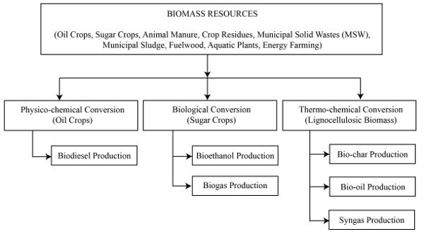
There are three fundamental biomass conversion pathways (Figure \(\PageIndex{1}\)): physico-chemical, biological, and thermal. Physicochemical conversion is the use of chemicals or catalysts for conversion at ambient or slightly elevated temperatures. Biological is the use of specific microbes or enzymes to generate valuable products. Thermo-chemical conversion occurs at elevated temperature (and sometimes pressure) for conversion. The products from biomass conversions can replace common fossil-resource-derived chemicals (e.g., lactic acid), fuel (e.g., diesel), and material (e.g., gypsum). This chapter focuses on energy derived by bioconversion.
Biodiesel Production
Refined vegetable oils and fats are converted into biodiesel, which is compatible with diesel fuel, by physicochemical conversion using a simple catalytic process using methanol (CH3OH) and sodium hydroxide (NaOH) at a slightly elevated temperature. The process is called transesterification. Vegetable oils are also called triglycerides because their chemical structure is composed of a glycerol attached to three fatty acid molecules by ester bonds. When the ester bonds are broken by a catalyst, glycerin is produced and the fatty acid compound is converted into its methyl ester form, which is the technical term for biodiesel. The combination of methanol and sodium hydroxide results in a compound called sodium methoxide (CH3ONa), which is the most common commercial catalyst for biodiesel production. The basic mass balance for the process is:
100 kg vegetable oil + 10 kg catalysts → 100 kg biodiesel + 10 kg glycerin
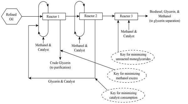
The energy balance depends on the specific facility design. For the biodiesel product to be considered viable, the energy in the biodiesel must exceed the energy used to produce the vegetable oil used for the process. In a commercial system, the transesterification process is split into several stages (Figure \(\PageIndex{2}\)). Methanol and catalysts are recovered after all the stages to minimize catalyst consumption. Crude glycerin is also recovered at each stage to minimize the use of excess methanol. The remaining catalyst—the amount must be calculated accurately—is then introduced at the last stage of the process. This last stage reaction minimizes unreacted mono-glycerides (or remaining glycerol that still has a fatty acid chained to it via an ester bond). If soybean oil is used, the resulting biodiesel product is called soybean methyl ester, the most common biodiesel product in the United States. In Europe, canola (rapeseed) oil is the most common feedstock, which produces rapeseed methyl ester. The glycerin co-product is further purified to improve its commercial value.
Bioethanol Production
Bioethanol, which is compatible with gasoline or petrol, is produced from sugar, starchy, or lignocellulosic crops using microbes or enzymes. Sugars from crops are easily converted into ethanol using yeast (e.g., Saccharomyces cerevisiae) or other similar microbes, while starchy crops need enzymes (e.g., amylases) that convert starch to sugar, with the yeasts then acting on the sugars to produce bioethanol. Lignocellulosic crops need similar enzymes (e.g., enzymes produced by Trichoderma reesei) to break down cellulose into simple sugars. The basic mass balance for the conversion of plant sugars from biomass into ethanol (C2H6O) also yields heat:
\(\mathrm{C}_{6} \mathrm{H}_{12} \mathrm{O}_{6}+\text { yeast } \rightarrow 2 \mathrm{C}_{2} \mathrm{H}_{6} \mathrm{O}+2 \mathrm{CO}_{2}(+\text { heat })\)
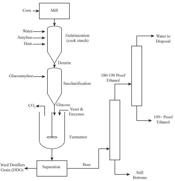
The most common feedstock for making bioethanol in the United States is dry milled corn (maize; Zea mays). In the process (Figure \(\PageIndex{3}\)), dry corn kernels are milled, then water is added to the powdered material while being heated (or gelatinized) in order to cook the starch and break it down using the amylase enzyme (saccharification). This process converts starch into sugars. The resulting product (mainly glucose) is then converted into bioethanol using yeasts fermentation for 3-5 days with a mass balance of:
\(2 \mathrm{C}_{6} \mathrm{H}_{10} \mathrm{O}_{5}+\mathrm{H}_{2} \mathrm{O}+\text { amylase } \rightarrow \mathrm{C}_{12} \mathrm{H}_{22} \mathrm{O}_{11}\)
or
\(\mathrm{C}_{12} \mathrm{H}_{22} \mathrm{O}_{11}+\mathrm{H}_{2} \mathrm{O}+\text { invertase } \rightarrow 2 \mathrm{C}_{6} \mathrm{H}_{12} \mathrm{O}_{6}\)
In this representation, complex starch molecules are represented by repeating units of polymers of glucose [(C6H10O5)n] with n being any number of chains. The enzyme amylase reduces this polymer into simple compounds, such as sucrose (C12H22O11), a disaccharide having just two molecules of glucose. Alternatively, the enzyme invertase is used to break down sucrose into glucose sugar. A yeast, such as the commercial yeast Ethanol Red (distributed by Fermentis of Lesaffre, France and sold worldwide) acts on the sugar product to convert the sugar into bioethanol. The resulting product (a broth) is called beer because its alcohol content is very close to 10%. The solid portion is called distillers grain, which is usually dried and fed to animals. The beer is distilled to yield solids (known as bottoms or still bottoms) and to recover 90-95% of the bioethanol (usually 180-190 proof), which is then purified using molecular sieves. (A molecular sieve is a crystalline substance with pores of carefully selected molecular dimensions that permit the passage of, in this case, only ethanol molecules.) The final separated and purified product may then be blended with gasoline or used alone.
Biogas Production
Biogas, which is composed primarily of methane (CH4; also called natural gas) and carbon dioxide (CO2), is produced from lignocellulosic biomass by microbes under anaerobic conditions. Suitable microbes are commonly found in the stomachs of ruminant animals (e.g., cows). These microbes convert complex cellulosic materials into organic acids via hydrolysis or fermentation; these large organic acids are further converted into simpler organic acids (e.g., acetic acids) and hydrogen gas. Hydrogen gas and some organic acids that include CO2 are further converted into CH4 and CO2 as the respiratory gases of these microbes. Biogas (CO2 + CH4) is the same as natural gas (CH4) if the CO2 component is removed. Natural gas is a common fuel derived by refining crude oil.
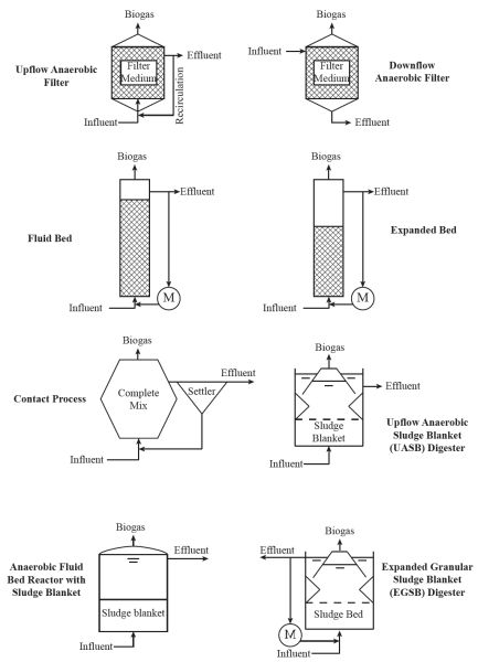
There are various designs of high-rate anaerobic digesters for biogas production (Figure \(\PageIndex{4}\)), which are commonly used in wastewater treatment plants worldwide. Simpler digesters use upflow and downflow anaerobic filters, basic fluidized beds, expanded beds, and anaerobic contact processes. One popular design from the Netherlands is the upflow anaerobic sludge blanket (or UASB) (Letingga et al., 1980). Improvements to the UASB include the anaerobic fluidized bed and expanded bed granular sludge blanket reactor designs. High-rate systems are commonly found in Europe, but there are few in the US. Most biogas plants in the US are simply covered lagoons.
Biomass Pyrolysis
Pyrolysis is a thermal conversion process at elevated temperatures in complete absence of oxygen or an oxidant. Figure 1.1.5 shows outputs and applications of pyrolysis. The primary products are solid bio-char, liquid, and gaseous synthesis gas. The ratios of these co-products depend on temperature, retention time, and type of biomass used. The quality and magnitude of products are also dependent on the reactor used. The simple rules of biomass pyrolysis processes are:
- 1. Solid bio-char (or charcoal) yield is maximized at the lowest pyrolysis temperature and the longest residence time.
- 2. Liquid yield is usually maximized at temperatures between 400°C and 600°C.
- 3. Synthesis gas, or syngas, is maximized at the highest operating temperature. The main components of syngas are carbon monoxide (CO) and hydrogen (H2). Other component gases include lower molecular weight hydrocarbons such as CH4, ethylene (C2H4), and ethane (C2H6).
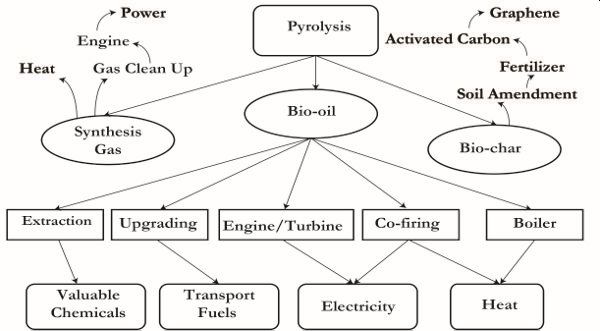
Bio-char may be used as a soil amendment to provide carbon and nutrients when applied to agricultural land. A high-carbon bio-char may also be upgraded into activated carbon, a very high-value adsorbent material for water and wastewater treatment processes. The highest value for the bio-char is achieved when the carbon is purified of all inorganics to generate graphene products, which are among the hardest materials made from carbon.
The quality of liquid product (bio-oil) is enhanced or improved with short residence times such as those in fluidized bed pyrolysis systems but not with auger pyrolyzers. Auger pyrolyzers usually have long residence times. Short residence times give rise to less viscous bio-oil that is easy to upgrade into biofuel (gasoline or diesel) using catalysts. Bio-oil from pyrolysis process has a wide range of applications (Figure \(\PageIndex{5}\)). Valuable chemicals can be extracted; the unaltered bio-oil can be upgraded via catalytic processes to generate transport fuels; and may be co-fired in an engine to generate electricity or in a boiler to generate heat.
Syngas may simply be combusted as it is produced to generate heat. However, syngas may need to be cleaned of tar before use in an internal combustion engine. To generate electrical power, this internal combustion engine is coupled with a generator.
Biomass Gasification
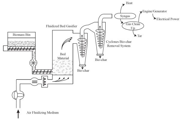
Gasification is a partial thermal conversion of biomass to produce syngas. In older textbooks, this gas is also synonymously called “producer gas.” Syngas can be combusted to generate heat or cleaned of tar and used in an internal combustion engine to generate electricity. The synthesis gas may also be used as feedstock to produce bio-butanol using microbes that also produce biofuel co-products. There are numerous types and designs of gasifiers, including fixed bed systems (updraft, downdraft, or cross-draft gasifiers) and moving bed systems (fluidized bed gasification systems).
A fluidized bed gasification system is shown in Figure \(\PageIndex{6}\). Biomass is continuously fed to a large biomass bin. The fluidized bed reactor contains a bed material, usually refractory sand, to carry the heat needed for the reaction. The air-to-fuel ratio is controlled so the amount of air is below the stoichiometric requirement for combustion (i.e., combustion is incomplete) to ensure production of synthesis gas instead of heat and water vapor. The solid remaining after partial thermal conversion is high carbon bio-char that is removed via a series of cyclones. The simplest application of this system is the production of heat by combusting the synthesis gas. If electrical power is needed, then the synthesis gas must be cleaned of tar to be used in an internal combustion engine to generate electricity. The conversion efficiencies of gasification systems are typically less than 20%. An average value to use for a quick estimate of output is around 15% overall conversion efficiency.
Biomass Combustion
Direct combustion of biomass has been a traditional practice for centuries; burning wood to produce heat for cooking is an example. Combustion is the most efficient thermal conversion process for heat and power generation purposes. However, not many biomass products can be combusted because of the high ash and water content of most agricultural biomass products. The ash component can melt at higher combustion temperatures, resulting in phenomena called slagging and fouling. Melted ash forms slag that accumulates on conveying surfaces (fouls) as it cools.
Economic Evaluation of Bioenergy Systems
Commercial bioenergy facilities depreciate every year. There is no accurate estimate of depreciation values but a potential investor may use this parameter to save on capital costs each year from the proceeds of the commercial facility such that at the end of the life of the facility, the investor is prepared to invest in higher-yielding projects.
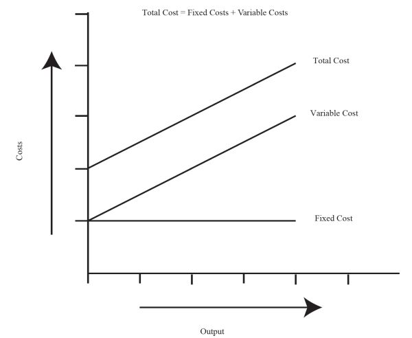
There are a number of simple methods that engineers may use for economic depreciation analyses of bioenergy facilities. A basic economic evaluation is required early in the design of the system to ascertain feasibility prior to significant capital investment. Evaluation of the economic feasibility begins with the analysis of the fixed (or capital) expenditures and variable (or operating) costs (Watts and Hertvik, 2018). Fixed expenditures include the capital cost of assets such as biomass conversion facilities, land, equipment, and vehicles, as well as depreciation of facilities and equipment, taxes, shelter, insurance, and interest on borrowed money. Variable costs are the daily or monthly operating costs for the production of a biomass product. Variable costs are associated with feedstock and chemicals, repair and maintenance, water, fuel, utilities, energy, labor, management, and waste disposal. Figure \(\PageIndex{7}\) shows the relationship between these two basic economic parameters. Fixed costs do not vary with time and output while variable costs increase with time and output of product. The total project cost is the sum of fixed and variable costs. Variable costs per unit of output decrease with increased amount of output, so the profitability of a product may depend on the amount produced.
In order to evaluate the economic benefits of a bioenergy project, some other economic parameters are commonly used (Stout, 1984), including net present value; benefit cost ratio, payback period, breakeven point analysis, and internal rate of return. The analyses must take into account the relationship between time and the value of money. The basic equations for estimating the present and future value of investments are:
\[ \text { Present Value }=\mathrm{PV}=\mathrm{FV} \times \frac{1}{(1+R)^{n}} \label{2} \]
\[ \text { Future Value }=\mathrm{FV}=\mathrm{PV} \times(1+R)^{n} \label{3} \]
where R = rate of return or discount rate (decimal)
n = number of periods (unitless)
The internal rate of return is a discounted rate that makes the net present value of all cash flows from a particular project equal to zero. The higher the internal rate of return, the more economically desirable the project. The net present value (Equation 1.1.4) is the difference between the present value of cash inflows and the present value of cash outflows. A positive net present value means that the project earnings exceed anticipated costs. The benefit cost ratio (Equation 1.1.5) is the ratio between the project benefits and costs. Values greater than 1 are desirable. The payback period (Equation 1.1.6) is the length of time required to recover the cost of investment.
When estimating the fixed cost of a project, the major cost components are the depreciation and the interest on borrowed money. There are many ways to estimate the depreciation of a facility. The two most common and simple methods are straight-line depreciation (Equation 1.1.7), and the sum-of-years’ digit depreciation method (SYD) (Equation 1.1.8).
\[ \text { Straight Line Depreciation }(\$)=\frac{\text { Principal-Salvage Value }}{\text { Life of Unit }} \label{7} \]
\[ \text { SYD Depreciation(\$) }=\text { Depreciation Base } \times \frac{\text { Remaining Useful Life }}{\text { Sum of Years' Digits }} \label{8} \]
In Equation 1.1.8, the depreciation base is the difference between the initial capital cost ($) and the salvage value of the asset ($). The sum of the years’ digits is the sum series: 1, 2, 3, up to n, where n is the useful life of the asset in years, as shown in Equation 1.1.9:
\[ \text { Sum of Years' Digits }=\mathrm{SYD}=\frac{n(n+1)}{2} \label{9} \]
The other large portion of capital cost is interest on borrowed money. This is usually the percentage (interest rate) charged by the bank based on the amount of the loan. The governing equation without including the salvage value (Equation 1.1.10) is similar to the amortization calculation for a loan amount:
\[ \text { Annuity }=A=P \times\left(\frac{r \times(1+r)^{n}}{(1+r)^{n}-1}\right) \label{10} \]
where
A = annuity or payment amount per period ($)
P = initial principal or amount of loan ($)
r = interest rate per period (%)
n = total number of payments or period (unitless)
There are many tools used for economic evaluation of energy system, but one of the most popular is the HOMER Pro (or hybrid optimization model for energy renewal) developed by Peter Lilienthal of the US Department of Energy (USDOE) since 1993 (Lilienthal and Lambert, 2011). The model includes systems analysis and optimization for off grid connected power systems for remote, stand-alone, and distributed generation application of renewables. It has three powerful tools for energy systems simulation, optimization, and economic sensitivity analyses (Capareda, 2014). The software combines engineering and economics aspects of energy systems. This type of tool is used for planning and design of commercial systems, but its simple equations can be used first to assess the fundamental viability of a biomass conversion project.
Sustainability Issues in Biomass Energy Conversion Systems
The US Department of Energy (USDOE) and US Department of Agriculture (USDA) define sustainable biofuels as those that are “economically competitive, conserve the natural resource base, and ensure social well-being.” The conservation of resource base points to the conservation of energy as well, that is, the fuel produced must have more energy than the total energy used to produce the fuel. One of the most common indicators of sustainability for biomass utilization is energy use throughout the life cycle of production. There are two measures used for this evaluation: the net energy ratio (NER) (Equation 1.1.11) and net energy balance (NEB) (Equation 1.1.12). NER must be greater than 1 and NEB must be positive for the system to be considered sustainable from an energy perspective.
\[ \mathrm{NER}=\frac{\text { Energy Content of Fuel }(\mathrm{MJ})}{\text { Energy Required to Produce the Biofuel }(\mathrm{MJ})} \label{11} \]
The heating value of the biofuel is defined as the amount of heat produced by the complete combustion of the fuel measured as a unit of energy per unit of mass.
Applications
Engineers assigned to design, operate, and manage a commercial biodiesel plant must decide what working system to adopt. The cheapest and most common is the use of gravity for separating the biodiesel (usually the top layer) and glycerin (the bottom layer). An example of this commercial operational facility is the 3 million gallon per year (MGY) (11.36 ML/yr) biodiesel plant in Dayton, Texas, operated by AgriBiofuels, LLC. This facility began operation in 2006 and is still in operation. The biodiesel recovery for this facility is slightly lower than those with computer-controlled advanced separation systems using centrifuges. This facility is also not following the ideal process flow (shown in Figure 1.1.2) used by many other commercial facilities. Thus, one would expect their conversion efficiency and biodiesel recovery to be lower.
Biodiesel production is an efficient biomass conversion process. The ideal mass balance equation, presented earlier, is:
100 kg vegetable oil + 10 kg catalysts → 100 kg biodiesel + 10 kg glycerin
The relationship shows that an equivalent mass of biodiesel is produced for every unit mass of vegetable oil used, but there are losses along the way and engineers must consider these losses when designing commercial facilities. In a commercial biodiesel facility, the transesterification process is split into several reactors (e.g., Figure \(\PageIndex{2}\)). However, to save on capital costs, some plant managers simply divide the process into two stages. Separating glycerin and biodiesel fuel is also an issue that the engineer will be faced with. Efficient separation systems that use centrifuges are expensive compared with physical separation, and this affects the overall economy of the facility. If the initial capital available is limited, investors will typically opt for cheaper, physical gravity separation instead of using centrifuges. Crown Iron Works (in Blaine, MN) sells low cost biodiesel facilities that employ gravity separation while GEA Wesfalia (Oelde, Germany) sell more expensive biodiesel facilities that use separation by centrifuge. The latter, expensive, system is more efficient at separating glycerin and biodiesel fuel and may be beneficial in the long term, allowing the facility to sell glycerin products with minimal contamination. The engineer may compare these systems in terms of costs and efficiencies. Ultimately Equation 1.1.2 is used for designing and sizing a commercial plant to determine the daily, monthly, or yearly vegetable oil requirement. This means the engineer must determine the agricultural land area required both for the facility and the supply of biomass. There are standard tables of oil yields from crops that are used. For example, the highest oil yield comes from palm oils, with more than 7,018 kg oil production per hectare compared with 2,245 kg/ha for soybean oil (Capareda, 2014).
Designing, building, and operating a commercial bioethanol facility also requires knowledge primarily on the type of feedstock to use. Unlike a biodiesel plant, where the manager may have various options for using numerous vegetable oil types without changing the design, a bioethanol plant is quite limited to the use of a specific feedstock. The main choices are sugar crops, starchy crops, or lignocellulosic biomass. Designs for these three different types of feedstock are not the same; using lignocellulosic biomass as feedstock is the most complex. The simplest are sugar crops but sugary juice degrades very quickly and so the majority of commercially operating bioethanol plants in the US use starchy crops like corn. Corn grains may be dried, ground, and stored in sacks for future conversion without losing its potency. Examples of commercial bioethanol plants using lignocellulosic feedstocks are those being built by POET (Sioux Falls, South Dakota) in Emmetsburg, Iowa, using corncobs (25 MGY or 94.6 ML/yr), and another by Dupont (Wilmington, Delaware) in Nevada, Iowa, using corn stover (30 MGY or 113.6 ML/yr).
Bioethanol is an efficient biofuel product. Engineers must be aware of energy and mass balances required for biofuels production even though other waste materials are also used for the processes. As the potential bioethanol yields from crops varies, the design is for a specific feedstock. The greatest potential bioethanol yield comes from the Jerusalem artichoke (Helianthus tuberosus) (11,219 L/ha). Compare this to corn (maize, Zea mays) at a reported yield of only 2,001 L/ha (Capareda, 2014) and sorghum (sorghum spp.) cane (4,674 L/ha) or grain (1,169 L/ha).
While yields are important, the location of a project is also a significant factor in selecting the resource input for a bioethanol or biodiesel production facility. For example, the Jerusalem artichoke has the highest bioethanol yield but only grows in temperate conditions. When the bioethanol business started to boom in the US around 2013, there was an issue with the disposal of a by-product of the process, the distillers grain. During those initial periods, these co-products were simply disposed of with very minimal secondary processing (e.g., animal feed) or to a landfill. Options for secondary valorization (i.e., to enhance the price or value of a primary product) have now emerged such as further energy recovery and as a raw material for products such a films and membranes. Key issues for engineers include sizing of plants and determining the daily, weekly, and monthly resource requirements for the feedstock, which can be calculated using Equations 1.1.3, 1.1.4, and 1.1.5, modified for inefficiency in practice.
A growing number of animal facilities have taken advantage of the additional energy recovered from anaerobic digestion of manure by converting their lagoons into biogas production facilities. In the US, the covered lagoon is still the predominant biogas digester design. The operation is very simple since the microorganisms needed for biogas production already exist in the stomachs of ruminants. Key issues for engineers are sizing (based on animal numbers), energy recovery rates, sizing of power production (engine) facilities, sludge production and energy remaining in the sludge and economic feasibility. There is increasing interest in designing systems that use sludge for pyrolysis to recover as much energy as possible from the feedstock. When these additional processes are adopted, the energy recovery from the waste biomass is improved and there is less overall waste. While the sludge is an excellent source of nutrients for crops, its energy value must be judged against its fertilizer value. Financially the energy case probably wins out, but a holistic analysis would be needed to judge the most desirable option from a sustainability perspective.
The economics of a biofuel facility are dependent on the price of the initial feedstock used. For example, 85% of the cost of producing biodiesel fuel comes from the cost of the initial feedstock. As a potential candidate for biodiesel production, if the price of refined vegetable oil is the same as the price of diesel fuel, it is not economical to turn the vegetable oil into a biofuel. The remaining 15% is usually the cost of catalysts used for the conversion process (Capareda, 2014). If biodiesel is made from any refined vegetable oil, the processing cost is the greatest component of the conversion process. The cost of chemicals and catalysts together usually amounts to approximately $0.06/L ($0.22/gal). Chemicals or catalysts are not the limiting factors in making biodiesel. This statement applies to biofuels in general. These production expenses are not a large part of the biofuels production expense. Biodiesel catalysts are rather cheap and abundant. They will not usually run out nor gets too expensive as production is increased.
In the bioethanol production process, the cost of the bioethanol fuel is also mainly affected by the price of the initial feedstock used, such as corn, as well as the enzymes used for the process. The process also uses significant volumes of water, but only minimal electricity. For example, for every 3.785 L (1 gallon) of bioethanol produced, 1.98 m3 (70 ft3) of natural gas and 155.5 L (41 gal) of water is required (Capareda, 2014). The electricity usage is around 0.185 kWh/L (0.7 kWh/gal). Hence, if the electricity cost is $0.10/kWh, then one would only spend around $0.0158/L (0.07/gal). Natural gas is used to heat up the beer and recover pure bioethanol. Because of the abundant use of water, this water input must be recycled for the process to be effective and efficient. The current industry standard for bioethanol production from grains is around 416.4 to 431.2 L/tonne (2.8–2.9 gal/bushel). Newer feedstocks for bioethanol production must exceed this value.
The economics of power production via thermal conversion such as pyrolysis or gasification is dependent upon the sale of electrical power. If a MW power plant using biomass is operated continuously for a year the electrical power should sell for $0.12/kWh to achieve a gross revenue of $1M. A preliminary economic evaluation of the economic return of a gasification for power facility can be completed by adjusting selling cost. Finally, the economics of biofuels production from biomass resources are also dependent on the price of crude oil from commercial distributors and importers. Biodiesel and bioethanol are mixed with commercial diesel and gasoline and are priced similarly. With a crude oil price below $100/barrel, the production cost for biodiesel and bioethanol must also be under $100/barrel.
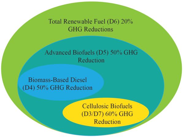
The question of the sustainability of fuel production and usage must be addressed. Many biofuels produced from biomass resources in the USA are now being categorized according to their potential greenhouse gas reductions and are standardized under the renewable fuels standard (RFS) categories (Figure \(\PageIndex{8}\)). As shown, cellulosic biofuels—mainly bioethanol and biodiesel (also coded as D3/D7, respectively) coming from lignocellulosic biomass—have a reported 60% greenhouse gas reduction compared with biomass-based diesel, which only has a 50% GHG reduction potential (also coded as D4). Biodiesel from vegetable oils and ethanol from corn have lower GHG reductions potential than cellulosic biofuels and biomass-based diesel. The code D6 is for renewable fuels in general, produced from renewable biomass and is used to replace quantity of fossil fuel present in transportation fuel, heating fuel, or jet fuel (e.g., corn ethanol) and also not falling under any of the other categories. The code D5 is for advanced biofuels other than ethanol derived from corn starch (sugarcane ethanol), and biogas from other waste digesters.
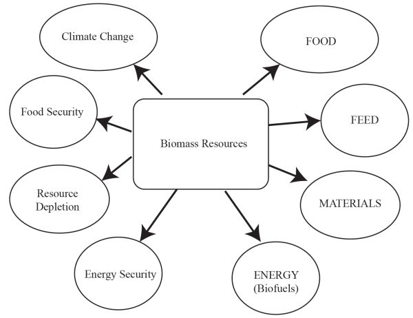
While net energy ratio (NER) and net energy balance (NEB) are important, they have to be combined with estimates of CO2 emissions and perhaps with land use to understand the foundations of sustainability of the use of biomass resources. A simple life cycle assessment (LCA) of coal and biomass for power generation (Mann and Spath, 1999) reported 1,022 g CO2 emissions per kWh of electrical power produced by coal compared to only 46 g CO2/kWh of electrical power by biomass. Contrary to the perception that using biomass would have zero net CO2 emissions, there is actually some CO2 produced for every kWh of electricity generated. It is also important to recognize the competing uses of land and biomass by society (Figure \(\PageIndex{9}\)). On one hand, biomass is used for food and feed (the food chain), and on the other for materials and energy (the bioeconomy). All uses have to consider climate change, food security, resource depletion, and energy security. Countries around the world need to create a balance of the use of biomass resources toward a better environment. Future engineers must be able to evaluate the use of biomass resources for materials and biofuels production as well as relate this to climate change and energy security without depleting already limited resources.
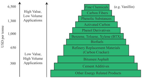
The US Department of Energy created a hierarchy of materials and products from biomass resources (Figure \(\PageIndex{10}\)). On top of the pyramid are high-value fine chemicals, such as vanillin and phenol derivatives, worth more than $6,500 per tonne. Phenol derivatives have the potential to be further converted into expensive lubricants (Maglinao et al., 2019). Next are high-value carbon fibers such as graphene, followed by phenolic substances. There are also new products such as 100% biomass-based printed integrated circuit boards developed by IBM (International Business Machines Corporation, Armonk, NY). Biofuels are in the middle of the pyramid, valued around $650 per tonne, with simple energy recovery by combustion at the bottom.
Examples
Engineers who manage biorefineries need to be aware of energy and mass balances to determine resource allocations, as well as conversion efficiencies to improve plant operations. The process of estimation includes simple conversion efficiency calculations and determining the economic feasibility of the biorefinery.
Example \(\PageIndex{1}\)
Example 1: Conversion efficiency calculations
Problem:
The ideal mass and energy balance is difficult to achieve. Plant managers must be able to estimate how close their operations are compared to the ideal conditions. The most common problem faced by a plant manager is to determine the conversion efficiency of refined vegetable oil into biodiesel. This example shows how the actual plant is operated and how close it is to the ideal mass balance. The energy content of refined canola oil is 39.46 MJ/kg and that of canola oil biodiesel was measured in the laboratory to be 40.45 MJ/kg. During an actual run, only about 95% biodiesel is produced from this refined canola oil input instead of the ideal 100% mass yield.
Determine the energy conversion efficiency of this facility from turning refined canola oil energy into fuel energy in biodiesel.
Solution
- 1. The energy of the output biodiesel product unit of weight is calculated using the 95% mass yield of biodiesel as follows:
- \( \text { Biodiesel Output }(\mathrm{MJ})=\frac{40.45 \mathrm{MJ}}{\mathrm{kg}} \times 0.95 \mathrm{~kg} \text { Biodiesel }=38.43 \mathrm{MJ}=36,424 \mathrm{Btu} \)
- 2. Using Equation 1.1.1, the conversion efficiency per unit of weight is:
- \( \text { Conversion Efficiency }(\%)=\frac{38.43 \mathrm{MJ}}{39.46 \mathrm{MJ}} \times 100 \%=97.4 \% \)
Biodiesel production is perhaps one of the most efficient pathways for the conversion of vegetable oil into biofuel, having very close to 100% energy conversion efficiency.
Example \(\PageIndex{2}\)
Example 2: Sizing commercial biodiesel plants
Problem:
Planning to build a commercial biodiesel facility requires taking inventory of input resources needed. In this example, the engineer must determine the amount of soybean oil needed (L/year) to build and operate a 3.785-million liter (1-million gallon per year, MGY) biodiesel plant. The densities of soybean oil and its equivalent biodiesel (also called soybean methyl ester) are as follows:
Calculate the soybean oil requirements for a daily basis and a monthly basis.
Solution
- 1. 3.785 million liters of biodiesel product is converted into its mass units as:
- \( \text { Biodiesel Mass Requirement }\left(\frac{\text { tonnes }}{\text { year }}\right)=\frac{3.785 \times 10^{6} \mathrm{~L}}{\text { year }} \times 0.88 \frac{\mathrm{kg}}{\mathrm{L}} \times \frac{\text { tonne }}{1000 \mathrm{~kg}}=3330.8 \frac{\text { tonnes }}{\text { year }}=3,671.6 \frac{\text { tonnes }}{\text { year }} \)
- 2. This biodiesel mass of 3,330.8 tonnes per year is then equivalent to the mass of soybean oil required for the plant. This unit must be converted into volumetric units for trading vegetable oils, as:
- \( \text { Soybean Oil Volume Requirement} \left(\frac{\mathrm{L}}{\text { year }}\right)=\frac{3,330.8 \text { tonnes }}{\text { year }} \times \frac{1,000 \mathrm{~kg}}{1 \text { tonne }} \times \frac{\mathrm{L}}{0.917 \mathrm{~kg}}=3,632,279 \frac{\mathrm{L}}{\text { year }}=959,651 \frac{\text { gallons }}{\text { year }} \)
- 3. Thus, the yearly soybean oil requirement for this biodiesel facility is more than 3.6 million liters (0.96 million gallons). The monthly and daily requirements are calculated as:
- \( \text { Soybean Oil Mass Requirement }\left(\frac{\mathrm{L}}{\text { month }}\right)=\frac{3,632,279 \mathrm{~L}}{\text { year }} \times \frac{1 \text { year }}{12 \text { months }}=302,689 \frac {\mathrm{L}} {\text { month }}=79,971 \frac{\text { gallons }}{\text { month }} \)
Further, this soybean oil requirement value may also be used to estimate the required acreage for soybean oil if one has data on soybean oil crop yield per acre. For example, a reported soybean oil yield of around 2,245 kg/ha (2000 lb/acre) (Capareda, 2014) will result in an estimated 1,483.6 ha (3,664 ac) needed for dedicated soybean land for this plant use year-round.
Example \(\PageIndex{3}\)
Example 3: Energy balance in the recovery of bioethanol
Problem:
Bio-ethanol may be produced from sweet sorghum via fermentation of its sugars. The sweet sorghum juice is fermented using yeasts (Saccharomyces cerevisiae). The resulting fermented product, called beer, has about 10% bioethanol. Higher percentage ethanol is required for engine use and may be separated from this fermented product through a simple distillation process. The liquid fermented product is simply heated until the bio-ethanol vapor is evaporated (around 80°C, the evaporation temperature of pure ethanol) and this vapor is condensed or liquefied in a simple condenser. In village-level systems, fuel wood is used to heat up the boiler where the fermented material is placed.
A village-level ethanol production scheme based on sweet sorghum has the following data for a series of experiments. In the first experiment, the operator was not mindful of the amount of fuel wood used for the recovery of highly concentrated ethanol and used too much, about 20 kg of waste fuel wood for the boiler. In addition, the boiler was not insulated during this run. In the second experiment, the operator insulated the boiler and was very careful in the use of fuel wood to adjust the boiler temperature below the boiling point of pure ethanol. Only about 10 kg of fuel wood was used, about half of the initial experiment. Assume that the energy of fuel wood is 20 MJ/kg and the heating value of ethanol is around 18 MJ/L. In both experiments, 120 liters of liquid fermented material (beer) was used and 13 liters of highly concentrated ethanol was recovered. Discuss the energy balance for each experiment.
Solution
- 1. In the first experiment, the operator used about 400 MJ of input energy and produced 13 liters of ethanol with an energy content of 234 MJ:
- \( \text { Energy from the Fuel Wood }=20 \mathrm{~kg} \text { fuel wood } \times \frac{20 \mathrm{MJ}}{\mathrm{kg}}=400 \mathrm{MJ} \)
- \( \text { Energy from the Ethanol }=13 \mathrm{~L} \times \frac{18 \mathrm{MJ}}{\mathrm{L}}=234 \mathrm{MJ} \)
- Clearly, the operator used more energy from the fuel wood than that of the recovered ethanol, demonstrating an unsustainable process.
- 2. The second experiment used only about 200 MJ of input wood energy, which is slightly less than the energy from the produced ethanol of 234 MJ.
- \( \text { Energy from the Fuel Wood }=10 \mathrm{~kg} \text { fuel wood } \frac{20 \mathrm{MJ}}{\mathrm{kg}}=200 \mathrm{MJ} \)
- By careful use of fuel wood, more energy from the bioethanol is recovered from a relatively efficient recovery process.
Note that there are other energy amounts expended from planting, harvesting, and transport of the sweet sorghum feedstock and this experiment is only one portion of the life cycle of bioethanol production, recovery, and use.
Example \(\PageIndex{4}\)
Example 4: Biogas production and use from animal manure
Problem:
Sizing a biogas facility is one task assigned to an engineer who operates a commercial biogas facility. One common calculation is to determine the electrical power produced from the manure collected from a 500-head dairy facility. Usually, one would need electrical power for 8 hours per day. The thermal conversion efficiency of an internal combustion engine is approximately 25% with a mechanical-to-electrical conversion efficiency of 80%. The specific methane yield was found to be 0.23 m3 biogas/kg volatile solids per day (Hamilton, 2012; ASABE Standard D384.2). Each mature dairy cow produces an average of 68 kg manure per head per day with a percentage of 7.5 volatile solids. The energy content of biogas was 24.2 MJ/m3 (650 Btu/ft3).
Size the generator to use for this facility.
Solution
- 1. The amount of methane produced from a 500-head facility is calculated as follows:
- \( \text { Biogas }\left(\frac{\mathrm{m}^{3}}{\text { day }}\right)=500 \text { head } \times \frac{68 \mathrm{~kg} \text { wet manure }}{\text { head per day }} \times \frac{0.075 \mathrm{~kg} \mathrm{VS}}{\mathrm{kg} \text { wet manure }} \times \frac{0.23 \mathrm{~m}^{3} \text { biogas }}{\mathrm{kg} \mathrm{VS}}=586.5 \frac{\mathrm{m}^{3}}{\text { day }} \)
- 2. The theoretical power production is calculated as follows:
- \( \text { Power }(k W)=\frac{586.5 \mathrm{~m}^{3}}{\text { day }} \times \frac{1 \text { day }}{8 \mathrm{hrs}} \times \frac{24,200 \mathrm{~kJ}}{\mathrm{~m}^{3}} \times \frac{1 \mathrm{hr}}{3600 \mathrm{~s}} \times \frac{\mathrm{kW}}{\mathrm{kJ} / \mathrm{s}}=492.8 \mathrm{~kW} \)
- 3. The actual power produced based on 25% engine efficiency and 80% mechanical-to-electrical efficiency is calculated as follows:
- \( \text { Actual Power }(\mathrm{kW})=492.8 \mathrm{~kW} \times 0.25 \times 0.80=98.6 \mathrm{~kW} \)
A generator with a size close to 100 kW of power output will be required.
Example \(\PageIndex{5}\)
Example 5: Basic biomass pyrolysis energy and mass balances
Problem:
The thermal conversion of waste biomass into useful energy is a common calculation for an engineer. This simple example is the conversion of coconut shell (waste biomass) into bio-char (useable fuel). In the experiment, the engineer used 1 kg of coconut shell and pyrolyzed this at a temperature of 300°C. The measured energy content of this high-energy density biomass was 20.6 MJ/kg. The pyrolysis experiment produced about 0.80 kg of bio-char. The heating value of the bio-char was measured to be 22 MJ/kg. Minimal solids and gaseous products were produced in this low-temperature pyrolysis process. Determine the overall conversion efficiency (ηe) for the bio-char conversion process and also calculate the amount of energy retained in the bio-char and the energy lost through the process.
Solution
- 1. Equation 1.1.1 is used directly to estimate the conversion efficiency for bio-char production.
- \( \text { Energy Conversion Efficiency }(\%)=\frac{\text { Energy Output }(\mathrm{MJ})}{\text { Energy Input }(\mathrm{MJ})} \times 100 \% \) (Equation \(\PageIndex{1}\))
- First, calculate the total energy of the bio-char per unit kg of material pyrolyzed as:
- \( \text { Bio-char Energy }(\mathrm{MJ})=0.80 \mathrm{~kg} \times \frac{22 \mathrm{MJ}}{\mathrm{kg}}=17.6 \mathrm{MJ} \)
- 2. The overall conversion efficiency (ηe) is then calculated as follows:
- \( \eta_{\mathrm{e}}=\frac{17.6 \mathrm{MJ}}{20.6 \mathrm{MJ}} \times 100 \%=85.4 \% \)
- This value also indicates the percentage of energy retained in the bio-char.
- 3. The energy lost through the process is simply the difference between the original energy of the biomass and the energy retained in the bio-char as follows:
- \( \text { Energy } \operatorname{Loss}(\mathrm{MJ})=20.6 \mathrm{MJ}-17.6 \mathrm{MJ}=3 \mathrm{MJ} \)
- 4. This energy loss is equivalent to 14.6%, the difference between 100% and the process conversion efficiency of 85.4%.
Notice the high yield of solid bio-char at this pyrolysis temperature, with a minimal yield of liquid and gaseous synthesis gas, which are considered losses at this point. However, at much higher pyrolysis temperatures, more liquid and gaseous synthesis gases are produced. Example 1.1.6 shows the uniqueness of the pyrolysis process in generating a wider range of co-products. Complete energy and mass balances of the process may also be estimated to evaluate overall conversion efficiencies.
Example \(\PageIndex{6}\)
Example 6: Basic biomass pyrolysis energy and mass balances
Problem:
An engineer conducted an experiment to pyrolyze 1.23 kg of sorghum biomass (heating value = 18.1 MJ/kg) at a temperature of 600°C in an auger pyrolyzer. The primary purpose of the experiment was to determine the energy contained in various co-products of the process. The input energy includes that from the auger motor (5 amps, 220 V) and tube furnace (2,400 Watts). The time of testing was 12 minutes. Data gathered during the experiments and other associated parameters needed to perform complete energy and mass balances are as follows:
- Amount of bio-char produced = 0.468 kg
- Volume of bio-oil produced = 225 mL
- Density of = 1.3 g/mL
- Volume of syngas produced = 120 L
- Heating value of bio-char = 23.99 MJ/kg
- Heating value of = 26.23 MJ/kg
The heating values of syngas produced as well as their composition is in the table below.
| Primary Gases | |||
|---|---|---|---|
| H2 | CH4 | CO | |
|
% Yield |
20% |
10% |
15% |
|
Density (kg/m3) |
0.0899 |
0.656 |
1.146 |
|
HV (MJ/kg) |
142 |
55.5 |
10.112 |
Determine an energy and mass balances for this process and report how much energy was contained in each of the co-products as well as the overall conversion efficiency.
Solution
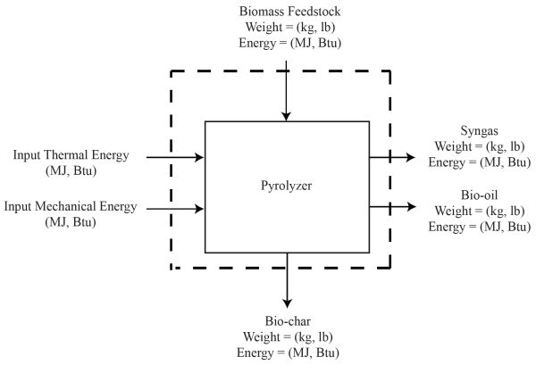
- 1. Draw a schematic of the complete mass and energy balance process as in Figure \(\PageIndex{11}\).
- 2. Calculate the energy contained in the original biomass as:
- \( \text { Biomass Energy }(\mathrm{MJ})=1.23 \mathrm{~kg} \times \frac{18.1 \mathrm{MJ}}{\mathrm{kg}}=22.26 \mathrm{MJ} \)
- 3. Calculate the input energy from the furnace as:
- \( \text { Thermal Energy }(\mathrm{MJ})=2.4 \mathrm{~kW} \times \frac{12 \mathrm{hr}}{60} \times \frac{3.6 \mathrm{MJ}}{1 \mathrm{kWh}}=1.728 \mathrm{MJ} \)
- 4. Calculate the input energy from the auger as:
- \( \text { Auger Energy }(\mathrm{MJ})=220 \mathrm{~V} \times 5 \mathrm{~A} \times \frac{\mathrm{kW}}{1,000 \mathrm{VA}} \times \frac{12 \mathrm{hr}}{60} \times \frac{3.6 \mathrm{MJ}}{1 \mathrm{kWh}}=0.792 \mathrm{MJ} \)
- 5. Calculate the energy contained in the bio-char as:
- \( \text { Bio-char Energy }(\mathrm{MJ})=0.468 \mathrm{~kg} \times \frac{23.99 \mathrm{MJ}}{\mathrm{kg}}=11.23 \mathrm{MJ} \)
- 6. Calculate the energy contained in the bio-oil as:
- \( \text { Energy }(\mathrm{MJ})=225 \mathrm{~mL} \times \frac{26.23 \mathrm{MJ}}{\mathrm{kg}} \times \frac{1.3 \mathrm{~g}}{\mathrm{~mL}} \times \frac{\mathrm{kg}}{1000 \mathrm{~g}}=7.67 \mathrm{MJ} \)
- 7. The total energy content of syngas is the sum of energy in the component gases. As given, about 120 L of syngas was produced, with 20% H2 (24 L), 10% CH4 (12 L) and 15% CO (18 L). The resulting energy content of the bio-oil is calculated as:
- \( \mathrm{H}_{2}(\mathrm{MJ})=24 \mathrm{~L} \times \frac{0.0899 \mathrm{~kg}}{\mathrm{~m}^{3}} \times \frac{1 \mathrm{~m}^{3}}{1,000 \mathrm{~L}} \times \frac{142 \mathrm{MJ}}{\mathrm{kg}}=0.306 \mathrm{MJ} \)
- \( \mathrm{CH}_{4}(\mathrm{MJ})=12 \mathrm{~L} \times \frac{0.0656 \mathrm{~kg}}{\mathrm{~m}^{3}} \times \frac{1 \mathrm{~m}^{3}}{1,000 \mathrm{~L}} \times \frac{55.5 \mathrm{MJ}}{\mathrm{kg}}=0.437 \mathrm{MJ} \)
- \( \mathrm{CO}(\mathrm{MJ})=18 \mathrm{~L} \times \frac{1.145 \mathrm{~kg}}{\mathrm{~m}^{3}} \times \frac{1 \mathrm{~m}^{3}}{1,000 \mathrm{~L}} \times \frac{10.112 \mathrm{MJ}}{\mathrm{kg}}=0.208 \mathrm{MJ} \)
- The total energy content of syngas is:
- \( \text { Syngas }(\mathrm{MJ})=0.306 \mathrm{MJ}+0.437 \mathrm{MJ}+0.208 \mathrm{MJ}=0.951 \mathrm{MJ} \)
- Most of the energy is still retained in the bio-char (11.23 MJ), followed by the bio-oil (7.67 MJ), and the syngas (0.951 MJ).
- 8. The energy balance is:
- \( \text { Input Energy }(\mathrm{MJ})=22.2 \mathrm{MJ}+1.73 \mathrm{MJ}+0.792 \mathrm{MJ}=24.722 \mathrm{MJ} \)
- \( \text { Output Energy }(\mathrm{MJ})=11.23 \mathrm{MJ}+7.67 \mathrm{MJ}+0.951 \mathrm{MJ}=19.851 \mathrm{MJ} \)
- 9. Calculate the conversion efficiency as:
- \( \text { Conversion Efficiency }(\%)=\frac{\text { Output }}{\text { Input }} \times 100 \%=\frac{19.851}{24.722} \times 100 \%=80.3 \% \)
Example \(\PageIndex{7}\)
Example 7: Present and future value of investment in a bioenergy systems facility
Problem:
An investor deposited $1,100,000 in a bank in 2007 rather than investing it in a commercial biodiesel facility. Determine its estimated future value in 2018 using the present value equation, assuming a bank rate of return of 2.36%. Compare this to investing the money in operating a biodiesel facility with year 11 return of $2M.
Solution
- 1. This is a simple future value calculation using Equation 1.1.3:
- \( \mathrm{FV}=\mathrm{PV} \times(1+r)^{n} \) (Equation \(\PageIndex{3}\))
where FV = future value of cash flow ($)
PV = present value of cash flow ($)
r = rate of return or discount rate (decimal)
n = number of periods (unitless)
\( \text { Future Value }=\$ 1,100,000 \times(1+0.0236)^{11}=\$ 1,421,758 \)
- 2. If invested in a bank, the future value after 11 years would be about $1.4M compared to a return of $2M from investing in the biodiesel facility. In this example, investing $1.1M in a biodiesel facility generated more value than putting the money in a bank.
Example \(\PageIndex{8}\)
Example 8: Depreciation of a biodiesel plant
Problem:
An engineer was asked to report the yearly depreciation for a biodiesel facility whose initial asset value is $1,100,000. The lifespan of the facility is 20 years and the salvage value of all equipment and assets at the end of this life is 10% of the initial capital value of the facility. Use the straight-line method and sum-of-digits method for depreciation calculations. Describe the yearly variations in depreciation for each method.
Solution
The straight-line method uses Equation 1.1.7:
\( \text { Straight Line Depreciation }(\$)=\frac{\text { Principal-Salvage Value }}{\text { Life of Unit }} \) (Equation \(\PageIndex{7}\))
\( =\frac{\$ 1,100,000-\$ 110,000}{20}=\$ 50,000 / \text { year } \)
The yearly depreciation after year 1 is $50,000 per year.
The sum of digits method first calculates the sum of digits as follows:
(1 + 2 + 3 + 4 + 5 + 6 + 7 + 8 + 9 + 10 + 11 + 12 + 13 + 14 + 15 + 16 + 17 + 18 + 19 + 20) = 210
The factor to estimate the depreciation for year 1 uses the reverse order—the life of the facility in the numerator and the sum of digits in the denominator with year 1 having a factor of 20/210 and so on.
\( \text { Year } 1 \text { Depreciation }(\$)=\frac{20}{210} \times(\$ 1,100,000-\$ 110,000)=\$ 94,285 \)
\( \text { Year } 2 \text { Depreciation }(\$)=\frac{19}{210} \times(\$ 990,000)=\$ 89,571 \)
\( \text { Year } 3 \text { Depreciation }(\$)=\frac{18}{210} \times(\$ 990,000)=\$ 84,857 \)
Continue calculations for years 4 through 19 using years 17 through 2 in the numerator. . . .
\( \text { Year } 20 \text { Depreciation }(\$)=\frac{1}{210} \times(\$ 990,000)=\$ 4,714 \)
Note that in both methods, the end of project asset cost is approximately equal to the salvage value given. If the data were plotted, a rapid decline in value over the first few years using the sum of digits method usually reflects the actual depreciation of many facilities.
Example \(\PageIndex{9}\)
Example 9: Calculation of net present value, benefit cost ratio, payback period, and internal rate of return for a biodiesel facility
Problem:
An engineer can be asked to evaluate a number of projects to estimate funding requirements. Comparative economic indicators can be used to compare one project proposal to another. Common indicators are net present value (NPV), benefit cost ratio (BCR), payback period (PBP), and internal rate of return (IRR). A 1,892,500 L/yr (half a million gallon per year) biodiesel facility with an initial capital cost of $1,100,000 and 10% salvage value has the following baseline data:
| Capital Cost (CC) | $1,100,000 | Repair & Maintenance Cost | 3% of Capital Cost | Biodiesel Plant Cost per million L | $581,241/ML ($2,200,000/MG) |
|---|---|---|---|---|---|
|
Interest |
7.5% |
Tax & Ins. |
2% of CC |
Conv. Eff. |
99% |
|
Life |
20 years |
Labor |
8 hrs/day |
Labor Cost |
$15/hr |
|
Vegetable Oil Price |
$0.13/L ($0.50/gal) |
Operation |
365 days/yr |
One Manager |
$60,000/yr |
|
Processing Cost |
$0.13/L ($0.50/gal) |
Personnel |
6 full-time |
Selling |
$0.53/L ($2.00/gal) |
|
Glycerin |
10% Yield |
Glycerin |
0.18/L ($0.7/gal) |
Biodiesel |
1,873,575 L (495,000 gals) |
|
Tax Credit |
28% |
Discount Rate |
2.36% |
Depreciation |
Straight Line |
|
Salvage Value |
10% of initial capital cost |
The data can be used to calculate some economic performance data:
- Average yearly gross income for the project with tax credit = $1,314,506
- Average yearly net income for the project with tax credit = $279,305
- Average discounted net benefits per year = $220,614
- Average discounted costs per year = $817,670
- Average discounted gross benefits = $1,038,284
Use these data to calculate NPV, BCR, PBP, and IRR.
Solution
- 1. Calculate the NPV from Equation 1.1.4,
- \( \mathrm{NPV}=\sum_{\mathrm{n}=1}^{\mathrm{N}} \frac{\text { cash inflow }}{(1+\mathrm{i})^{\mathrm{n}}}-\text { cash outflow } \) (Equation \(\PageIndex{4}\))
- or simply get the difference between the average yearly discounted benefits and the yearly average discounted costs:
- \( \mathrm{NPV}=\$ 1,038,284-\$ 817,670=\$ 220,614 \)
- The NPV value is positive. Hence, the project is economically feasible.
- 2. The BCR is the ratio between the discounted benefits and discounted costs as shown:
- \( \mathrm{BCR}=\frac{\text { project benefits }}{\text { project costs }} \) (Equation \(\PageIndex{5}\))
- \( =\frac{\$ 1,0.38,284}{\$ 817,670}=1.27 \)
- The BCR is greater than 1, also showing the project is feasible.
- 3. The PBP is the ratio of the initial capital costs and the yearly average discounted net revenue:
- \( \text { PBP }(\text { years })=\frac{\text { project costs }}{\text { annual cash inflows }} \) (Equation \(\PageIndex{6}\))
- \( =\frac{\$ 1,100,000}{\$ 220,614}=5 \text { year } \)
- 4. To calculate the internal rate of return, compare the discounted net benefits throughout the life of the project with an assumed discount factor (discount rate). Manually, this is a trial-and-error method whereby the assumed discount rate results to net benefits greater than zero (positive) and less than zero (negative). The discount rate where the net benefit is exactly equal to zero is the internal rate of return for the project.
For example, when the above data is encoded in a spreadsheet and the assumed discount rate is 30%, the discounted net benefit is estimated at −$173,882, a negative value. However, when the discount rate of 20% is used, the discounted net benefit is calculated as $260,098, a positive value. Hence, the internal rate of return must be between these assumed values (that is, between 20% and 30%). By ratio and proportion (plotting these values in X-Y Cartesian coordinates, like cash flow, and comparing the smaller triangle with the larger triangle, the X being the discounted factor above 20% and Y the net benefits in $), the internal rate of return is then calculated as follows:
-
\( \frac{\mathrm{X}}{\$ 260,098}=\frac{(30 \%-20 \%)}{(\$ 260,097+\$ 173,882)} \)
-
\( X=6 \% \)
-
\( \mathrm{IRR}=20 \%+6 \%=26 \% \)
- Thus the IRR must be around 26%, a positive value and higher than the bank interest rate of 7.5%. The project is then declared economically feasible using this parameter. (Note: When calculated by spreadsheet, the IRR values will be slightly different from this manual method).
Example \(\PageIndex{10}\)
Example 10: Determining net energy ratio and net energy balance for corn ethanol with and without co-products recycling
Problem:
To assess the merit of converting biomass into fuel as recommended by USDA it is possible to use of the net energy ratio (NER) and net energy balance (NEB) for a facility. Numerous studies conducted by USDA for corn ethanol production from wet milling and dry milling have established baseline data.
The total energy used for each process, without considering the use of co-products as sources of additional energy:
- Total energy used for the dry milling process = 19.404 MJ/L
- Total energy used for the wet milling process = 20.726 MJ/L
- Heating value of ethanol produced = 21.28 MJ/L
The total energy used for each process when all by the products of the system are used to supply energy requirements for the facility:
- Total energy used for the dry milling process = 15.572 MJ/L
- Total energy used for the wet milling process = 16.482 MJ/L
- Heating value of ethanol produced = 21.28 MJ/L
Determine whether it is better to use wet or dry milling, and whether it is better to use co-products as a source of energy within the facility.
Solution
- 1. The NER is calculated using Equation 1.1.11:
- \( \mathrm{NER}=\frac{\text { Energy Content of Fuel }(\mathrm{MJ})}{\text { Energy Required to Produce the Biofuel }(\mathrm{MJ})} \) (Equation \(\PageIndex{11}\))
For the dry mill process, \( \mathrm{NER}=\frac{21.28 \mathrm{MJ} / \mathrm{L}}{19.404 \mathrm{M} / \mathrm{L}}=1.10 \)
For the wet mill process, \( \mathrm{NER}=\frac{21.28 \mathrm{MJ} / \mathrm{L}}{20.726 \mathrm{M} / \mathrm{L}}=1.03 \)
- The dry mill process has a higher NER than the wet mill process.
- 2. The NEB is calculated using Equation 1.1.12:
- \( \text { NEB = Biofuel Heating Value(MJ) - Energy Required to Produce the Biofuel(MJ) } \) (Equation \(\PageIndex{12}\))
- For the dry mill process, \( \mathrm{NEB}=21.28 \frac{\mathrm{MJ}}{\mathrm{L}}-19.404 \frac{\mathrm{J}}{\mathrm{L}}=1.876 \)
- For the wet mill process, \( \mathrm{NEB}=21.28 \frac{\mathrm{MJ}}{\mathrm{L}}-20.726 \frac{\mathrm{J}}{\mathrm{L}}=0.554 \)
- The dry milling process is better than the wet milling process according to both the NER and NEB when co-products are not used to supply energy.
- 3. The NER for the dry mill process with co-products allocation is:
- \( \mathrm{NER}=\frac{21.28 \mathrm{MJ} / \mathrm{L}}{15.572 \mathrm{M} / \mathrm{L}}=1.37 \)
- The NER for the wet mill process when co-products are reused is:
- \( \mathrm{NER}=\frac{21.28 \mathrm{MJ} / \mathrm{L}}{16.482 \mathrm{M} / \mathrm{L}}=1.29 \)
- 4. The NEB for the dry mill process when co-products are reused for the process is:
- \( \mathrm{NEB}=21.28 \frac{\mathrm{MJ}}{\mathrm{L}}-15.572 \frac{\mathrm{J}}{\mathrm{L}}=5.708 \)
- The NEB for the wet mill process when co-product are reused for the process is:
- \( \mathrm{NEB}=21.28 \frac{\mathrm{MJ}}{\mathrm{L}}-16.482 \frac{\mathrm{J}}{\mathrm{L}}=4.798 \)
- The dry milling process remains the better option and both NER and NEB indicate that the co-products should be used as part of the system design.
Image Credits
Figure 1. Capareda, S. (CC By 4.0). (2020). Pathways for the conversion of biomass resources into energy.
Figure 2. Capareda, S. (CC By 4.0). (2020). Schematic of the commercial process of making biodiesel fuel.
Figure 3. Capareda, S. (CC By 4.0). (2020). Schematic of the commercial process for making bioethanol via dry milling.
Figure 4. Capareda, S. (CC By 4.0). (2020). Schematic representation of various designs of high-rate biogas digesters.
Figure 5. Capareda, S. (CC By 4.0). (2020). The outputs and applications of biomass pyrolysis.
Figure 6. Capareda, S. (CC By 4.0). (2020). Schematic diagram of a fluidized bed gasifier.
Figure 7. Capareda, S. (CC By 4.0). (2020). The relationships between capital expenditure (CAPEX) and operating expenditure (OPEX) for a bioenergy project.
Figure 8. Capareda, S. (CC By 4.0). (2020). Schematic of US nested renewable fuels categories under the renewable fuels standards.
Figure 9. Capareda, S. (CC By 4.0). (2020). The role of biomass resources for a sustainable low-carbon future.
Figure 10. Capareda, S. (CC By 4.0). (2020). Hierarchy of biomass utilization from high-value, low-volume applications (top) to low-value, high-volume applications (bottom).
Figure 11. Capareda, S. (CC By 4.0). (2020). Distribution of mass and energy from all products of the pyrolysis process.
References
Capareda, S. (2014). Introduction to biomass energy conversions. Boca Raton, FL: CRC Press. https://doi.org/10.1201/b15089.
Hamilton, D. W. (2012). Organic matter content of wastewater and manure, BAE 1760. Stillwater: Oklahoma Cooperative Extension Service.
Lettinga, G., van Velsen, A. F., Hobma, S. W., de Zeeuw, W., & Klapwijk, A. (1980). Use of the upflow sludge blanket (USB) reactor concept for biological wastewater treatment, especially for anaerobic treatment. Biotech. Bioeng., 22(4), 699-734. doi.org/10.1002/bit.260220402.
Lilienthal, P., & Lambert, T. W. (2011). HOMER. The micropower optimization model. Getting started guide for HOMER legacy. Ver. 2.68. Boulder, CO and Golden, CO: Homer Energy and NREL USDOE.
Maglinao, R. L., Resurreccion, E. P., Kumar, S., Maglinao, A. L., Capareda, S., & Moser, B. R. (2019). Hydrodeoxygenation-alkylation pathway for the synthesis of a sustainable lubricant improver from plant oils and lignin-derived phenols. Ind. Eng. Chem. Res., 1-50. https://doi.org/10.1021/acs.iecr.8b05188.
Pimentel, D. (2003). Ethanol fuels: Energy balance, economics, and environmental impacts are negative. Natural Resour. Res., 12(2), 127-134. https://doi.org/10.1023/A:1024214812527.
Stout, B. A. 1984. Energy use and management in agriculture. Belmont, CA: Breton Publ.
Watts, S., & Hertvik, J. (2018). CapEx vs OpEx for IT & Cloud: What’s the difference? The Business of IT Blog, January 2 issue. Retrieved from https://www.bmc.com/blogs/capex-vs-opex/.


