
6.1: Decoding a machine code instruction
- Page ID
- 76120

The process of decoding an instruction consists of taking the 32-bit instruction and breaking it into groups of data that are then passed on to other units in the CPU. These groupings fall into the following basic types:
- Specific register types (e.g., Rd, Rn, Rm, Rs) that contain the register number to use for these registers (e.g., 0b0000 for r0, 0b0001 for r1).
- Numeric data, such as the Immediate and ShAmt values. Note that the numeric values in assembly instructions can be different sizes. For example, the ShAmt is a 4-bit number when it represents a rotation in an Immediate expression, but is a 5-bit number in a Numeric Shift Instruction. The Immediate value can be 4, 8, or 12 bits depending on the type of instruction. For these values, the maximum number of bits (5 bits for the ShAmt and 12 bits for the Immediate) will be sent to the other CPU units, and those units are responsible for proper processing the data.
- Control data, bits that indicate to the CPU the type of instruction, will be forwarded to the CU, ALU, and barrel shifter to properly set up the CPU to handle the instruction. While these units are the heart of the CPU, it is complex, and is a topic separate from assembly language.
In the MSCPU, a Decoder unit will be placed between the Text Memory, which retrieves the 32- bit instruction from Text Memory, and the rest of the CPU which will use the parts of the instruction. A black box Decoder unit is shown in Figure 31. The input is the 32-bit instruction, and the outputs are the numeric Immediate and ShAmt values, the Rd, Rm, Rn, and Rs register numbers, and the control information.
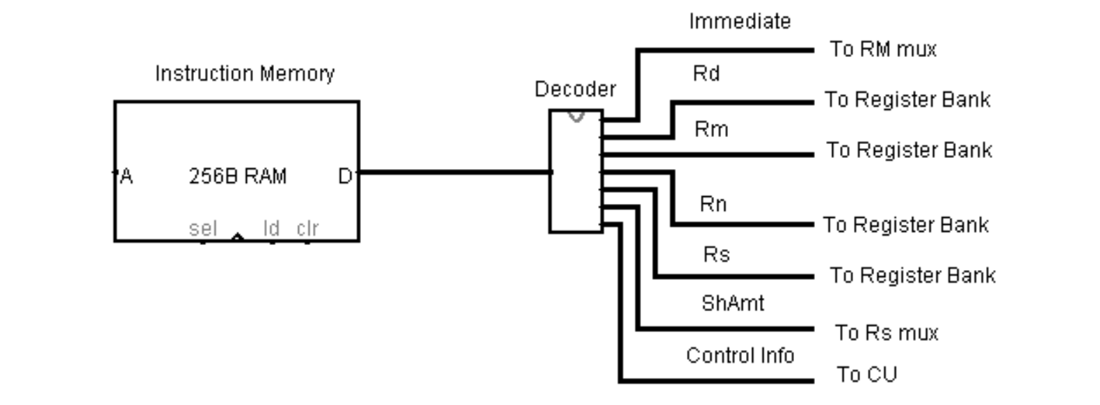
Figure 31: Decoder black box diagram
How the decoding of the instruction is achieved will now be built in stages. The first iteration will use a splitter to break the instruction into 32 separate wires and then to create register number output to forward to the Register Bank.
To start we examine Appendix 3, which gives the machine code formats of all the 3-Address instructions. The Register Instruction gives uses all the registers in a single instruction and is reproduced in Figure 32.

Figure 32: Register Instruction
This instruction shows where each of the register numbers that occur in all instructions, generally called Rd, Rm, Rn, and Rs, are located in the instructions. These registers will sometimes be referred to by other names (such as Rt for the ldr and str instructions), and some instructions use other register convention (such as the mul instruction that swaps Rd and Rn). However, these anomalous cases require the CPU to have a knowledge of the instructions being processed to know how to handle them, and since the Decoder unit has no way to know the instruction type, the register identifiers in the register instruction shown above will still be used. The responsibility for determining any anomalous meaning of the registers will be the responsibility of the downstream processing units, in this case the Register Bank. The decoder simply moves 4 bits from a specified position in the instruction to the 4-bit output value. In this case, bits 0-3 are moved to the Rm output, bits 8-11 are moved to the Rs output, bits 12-15 are moved to the Rd output, and bits 16-19 are moved to the Rn output. This is shown in the first iteration of the Decoder below.
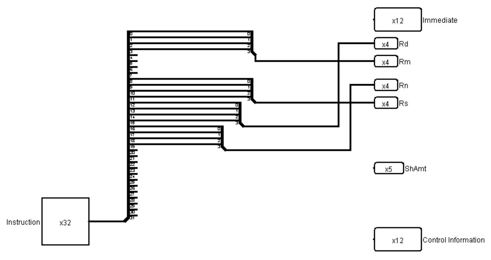
Figure 33: Decoder showing the mapping of instruction to register numbers
The next iteration of the decoder will process the output to the Immediate and the ShAmt. To see where these numeric values occur in a Register Format, Operand2 with ShAmt and a Load/Store Immediate Instruction are reproduced in Figures 34 and 35. The maximum ShAmt is instruction bits 7...11, and the maximum immediate value is instruction bits 0...11.
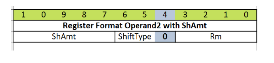
Figure 34: Immediate Instruction

Figure 35: Load/Store Immediate Instructions
Once again there are anomalous conditions where the ShAmt and Immediate value are different sizes depending on the instructions. Again, the largest value is parsed from the input, and the downstream CPU units are responsible for using the values correctly.
Note that both the ShAmt and Immediate have wires that overlap the wires for the registers. This does not cause any problems as the overlap occurs for different instructions, thus the values for the registers and immediate values are always correct for the instruction being executed. Again, since the Decoder has no way to determine which instruction is being executed, or how many bits to put on the output wires, it will always provide the maximum number of bits to these values, relying on other units to adjust to the proper number of bits used.
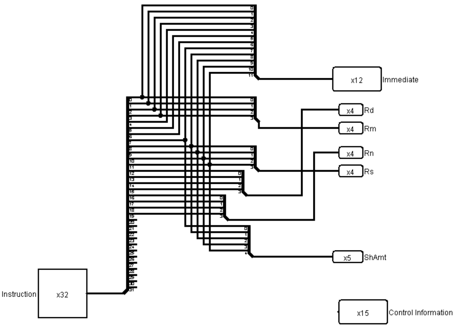
Figure 36: Decoder with added Immediate and ShAmt values
Finally, the control information needs to be forwarded. For now, all the control information is just grouped together and sent to a single output port. The control information is 15-bits of information, and includes the CondCode, OpType, OpCode, and ShiftType. This final iteration of the decoder is presented in the following figure, which represents the final implementation of the Decoder.
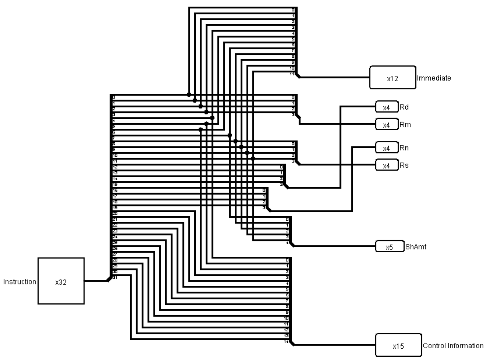
Figure 37: Final Decoder implementation