
6.2: Machine Code Instruction Formats
- Page ID
- 76121

This section will present the machine code instruction formats for the operations that were presented in Chapters 4 and 5. These machine code instruction formats can be found in Appendix 3 and are documented in a separate spreadsheet. The format used to present these instructions is encoded as follows:
- Any column in red should be entered exactly as they appear here. They will be explained later in the text. However, for producing machine code for the current version of the MSCPU, they should all be treated as constants.
- Fields in blue are control information that are used to define the specific machine code type. These should also be treated as constants for the transaction type.
- Fields in green are fields of data that must be specified for the machine code type. Some of these fields will contain control information (such as the OpCode for Register and Immediate Instruction), others will contain number data (the Immediate and ShAmt values), and finally some will be register numbers.
These formats are broken down into 3 categories: shift and mov operations, data processing operations, and load/store operations.
6.2.1 Operand2 definition
The Operand2 is often the third operand (or second input operand) in immediate and register instructions and second operand (or the only input operand) in register MOV instructions. Therefore, to understand the machine code format of any of the subsequent statements, first the Operand2 must be understood. The definition of Operand2 will be covered using the MOV operation.
The Operand2 occupies the least significant 12 bits of the instruction (bits 0...11) for Immediate and Register instructions. There will be 3 formats for the Operand2. There is one format for the Operand2 for Immediate instructions and two formats for the Register instructions.
For an immediate instruction (OpType = “001”), there is one type of Operand2 that is an 8-bit immediate value with a 4-bit amount to rotate the immediate. This text will call this an Immediate Format Operand2. The 12-bit format is shown in Figure 38.
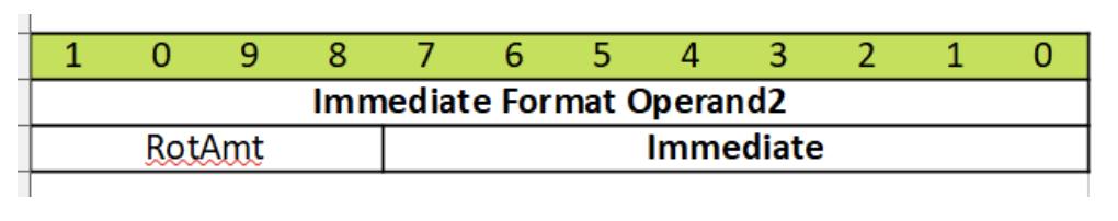
Figure 38: Immediate Format Operand2
If the instruction is a register instruction (OpType=“000”), there are two formats for the Operand2. Both of these will use the Rm register, and allow the ShiftType to be specified. They differ in how they get value of the amount to shift. The Register Format Operand2 with ShAmt is specified by a 0 in bit 4 (the fifth bit) of the instruction and contains a 5-bit shift amount value in the Rm register. It is shown in Figure 39.
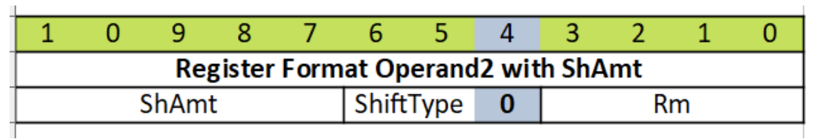
Figure 39: Register Format Operand2 with ShAmt
The Register Format Operand2 with Register is specified by a 1 in bit 4 (the fifth bit) of the instruction and uses the Rs register to specify how much to shift the value in Rm. It is shown in Figure 40.
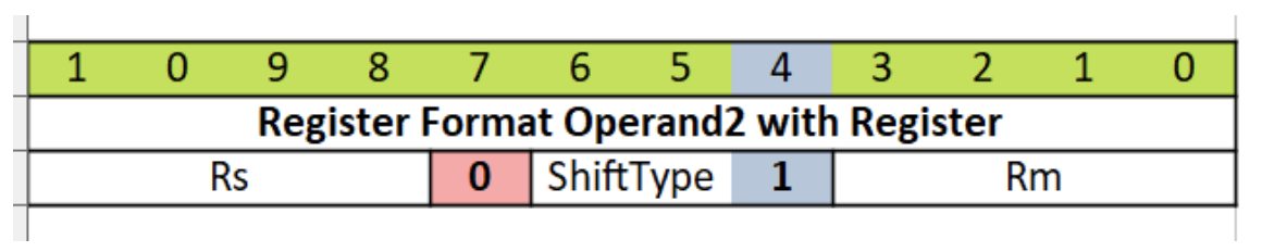
Figure 40: Register Format Operand2 with Register Amount
Note that the ShiftType is needed for these two instructions, and so a table of ShiftType values is given in Table 8. Note that to determine the type of shift, only two bits are needed. The third bit determines if the value to shift is ShAmt or a register.
OpType: 000 Special, OpCode: 1110 - Shift Operations
| OpCode | ShiftType | Meaning | Inst Type | |
|---|---|---|---|---|
| 1101 | 000 | MOV | R | bits 4-11 bits also zero, otherwise converted to Shift inst. |
| 1101 | 00[0/1] | LSL | Shift | 0 is ShAmt, 1 is Register |
| 1101 | 01[0/1] | LSR | Shift | 0 is ShAmt, 1 is Register |
| 1101 | 10[0/1] | ASR | Shift | 0 is ShAmt, 1 is Register |
| 1101 | 11[0/1] | ROR | Shift | 0 is ShAmt, 1 is Register |
| 1101 | 110 | RRX | Shift | Shift using R only, but Bit 4 is 0: Bits 7-11 are 0 |
Table -8: Shift Operations
The use of the Operand2 value is illustrated in the next section using the MOV instruction.
6.2.2 Operand2 with MOV instruction
The MOV instruction is presented first because once the immediate operation is understood, all of the other instructions can be understood as modifications of the MOV instruction.
The MOV instruction is defined by an OpType = 00[01] and an OpCode = 1101.
The MOV instruction has three formats; the first format does not use a Shift operation, and the Rm value is passed on unchanged, and is effectively a 3-address instruction; the second passes on a rotated Immediate value; and the third is a register operation. The second and third type differ by the least significant bit of the OpType and by the type of the Operand2 they are support.
The first type of MOV operation is simply a 3-address instruction format of the MOV. An example is the following:
MOV Rd, Rs, Rm
An example of this instruction is:
MOV r1, r2
In this instruction, the Operand2 contains the Rm value, but the rest of the bits in Operand2 (bits 4-11) are zero. As will be seen in the next chapter, this correspond to a LSL with a shift of 0 bits, which is a meaningless LSL operation.
The machine code format of this MOV instruction is:

Figure 41: Machine code format for a 3-address MOV instruction
This 32-bit value is hard to read, so it is generally expressed in hexadecimal as 0xe1a01002.
The second type of MOV is an immediate MOV. Remember from Chapter 5.4.2, the immediate MOV can have the format:
MOV Rd, Immediate, ShAmt (even values only)
An example of this format would be:
MOV r1, #3, 4
The machine code format of the immediate MOV instruction is:

Figure 42: Machine code format for an immediate MOV instruction
Since this instruction uses the Immediate Format Operand2, the ShAmt (amount of the rotation) is 0b0010 in bits 8..11 of the instruction, and the Immediate value is 0b00000011 in bits 0...7. Filling in the green boxes in Figure 43 below with Rd = r1 (0b0001):

Figure 43: Binary value for instruction MOV r1, #3, 4
This 32-bit value expressed in hexadecimal is 0xe3a01203.
The third format of the MOV instruction is the register MOV instruction. Remember from Chapter 5.4.3 the MOV has a register format of:
MOV r1, Operand2
This corresponds to a machine code format shown in Figure 44:

Figure 44: Machine code format for a Register MOV Instruction
There are now two possible formats for the register MOV instruction. The first is with a Register Format Operand2 with ShAmt. An example is shown in the instruction below:
MOV r1, r2, lsl #3
Filling in the instruction with the proper values, Rd = r1 = 0b0001, Rm = r2 = 0b0010, ShAmt = 3 = 0b00011, and ShiftType = LSL = 0b00, this MOV instruction would have a binary value given in Figure 45.

Figure 45: Machine code format for a Register MOV Instruction with ShAmt
The hexadecimal value of this instruction is 0xe1a01182.
The final possibility for a MOV instruction is a Register Format Operand2 with Register. An example is shown in the instruction below:
MOV r1, r2, ASR r3
Filling in the instruction with the proper values, Rd = r1 = 0b0001, Rm = r2 = 0b0010, Rs = r3 = 0b0011, and ShiftType = ASR = 0b10, this MOV instruction would have a binary value given in Figure 46.

Figure 46: Machine code format for a Register MOV Instruction with Register
The hexadecimal value of this instruction is 0xe1a01352.
To test our logic and see if it is correct, a program is written with these three instructions in it, and then compiled to an object file. The program, which was written in a file called machine.s, is the following:
.text
.global main

main:
    SUB sp, sp, #4
    STR lr, [sp, #0]

    MOV r1, r3
    MOV r1, #3, 4
    MOV r1, r2, lsl #3
    MOV r1, r2, asr r3

    LDR lr, [sp, #0]
    ADD sp, sp, #4
    MOV pc, lr
.data
8 Program to check machine code instructions
To compile this program, the command “gcc machine.s -c -o machine.o” was run, and the command objdump was run on the resulting object file using the command “objdump machine.o -d”. This produced the output shown on the following screen shot.
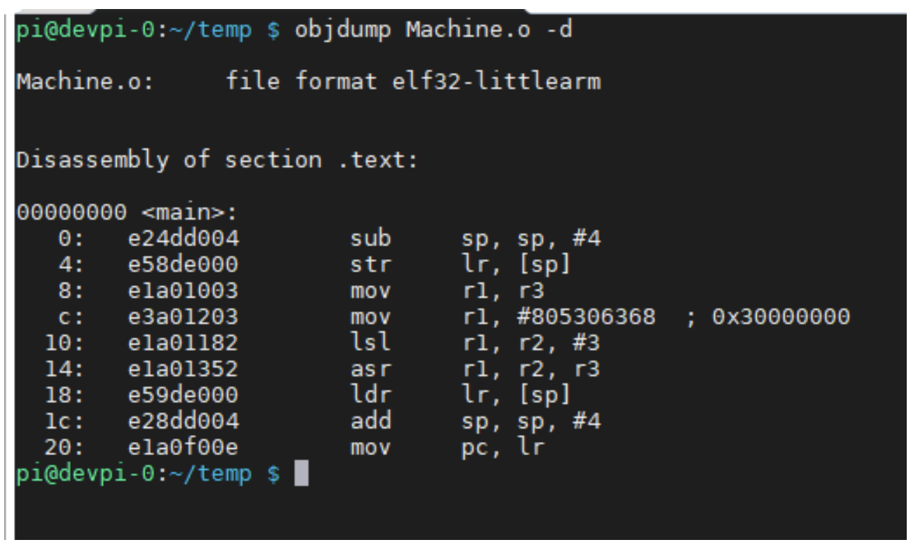
Figure 47: Output from dumping an object file
The second column in the output from running the objdump command gives the hexadecimal value of the object code the command produced. Notice that the output corresponds to the calculated values.
6.2.3 Shift operations
There is more to see in the objdump output in Figure 47 than just the hex values of the instructions. Note that the register MOV instructions were printed out as the shift instructions LSL and ASR, not the MOV instructions we originally inputted. The reason for this is that every shift instruction has a corresponding register MOV instruction.
The register instructions:
    MOV r1, r2, LSL #3
    MOV r1, r2, ASR r3
are the equivalent in machine code as the following shift equations:
    LSL r1, r2, #3
    ASR r1, r2, r3
Thus, there is no need to cover the machine code format for the shift instructions since it is only necessary to covert the shift instructions into register MOV instructions, for which the translation to machine code has already been covered.
6.2.4 Data operation Instruction Formats
Data operations are the logical and arithmetic operations executed in the ALU. The operations are given in Table 9.
OpType: 00[0/1] - Data Operation
| OpCode | Meaning | Inst Type | Action | |
|---|---|---|---|---|
| 0000 | AND | I/R | operand 1 AND operand 2 | |
| 0001 | EOR | I/R | operand 1 EOR operand 2 | |
| 0010 | Subtract | I/R | operand 1 - operand 2 | |
| 0011 | RSB | I/R | operand 2 - operand 1 | |
| 0100 | Add | I/R | operand 1 + operand 2 | |
| 1100 | ORR | I/R | operand 1 OR oeprand 2 | |
| 1110 | MOV | I | For I, operand 1 \(\leftarrow\) operand 2, for R see table below | |
| 1110 | Shift | R only | See table below |
Table -9: Shift Operations
There are two formats for the data operations, an Immediate format, specified by an OpType = “001” and a Register format specified by an OpType = “000”. These two formats are shown in Figures 48 and 49 below.

Figure 48: Immediate Instruction

Figure 49: Register Instruction
There are two difference between the MOV operation and the other data operations. The first difference is that the MOV instruction does not have the Rn register that is needed for all the other data operations. The other difference is that an OpCode needs to be specified for the Immediate and Register Instructions. These OpCode values are specified in the first column in Table 9.
To see how to apply these formats to an instruction, consider the two instructions below. The first is a register ADD instruction.
ADD r1, r2, r3, LSL #5
Using Table 9, the ADD operator has an OpCode = “0b0100”, the Operand2 uses a ShiftAmt =”0b00101”, from Table 8 the ShiftType = LSL = “0b00”, and registers Rd = r1 = “0b0001”, Rn = r2, “0b0010”, and Rm = r3 = “0b0011”. Using these values in the Immediate instruction, the 32-bit representation of this instruction is shown in Figure 50.

Figure 50: Machine Code for ADD r1, r2, r3, LSL #5
This 32-bit value in hexadecimal is 0xe0821283.
The next instruction is an immediate ORR instruction.
ORR r1, r2, #260 // Note #260 = 0x21, 30, or ORR r1, r2, #0x21, 30
Using Table 9, the ORR operator has an OpCode = “0b1100”, the Operand2 uses an Immediate value = “0x21”, the ShAmt = 30 = “0xffff”, the ShiftType is an implied RRX, and registers Rd = r1 = “0b0001”, Rn = r2, “0b0001”. Using these values in the Immediate instruction, the 32-bit representation of this instruction is shown in Figure 51.

Figure 51: Machine Code for ORR r1, r2, #260
This 32-bit value in hexadecimal of 0xe3821f21. Assembling these instructions yields these machine code values.
6.2.5 Multiply operation
The Multiply (MUL) register instruction is a data operation. The register instruction is indicated by an OpType = “000”, an OpCode = “0000”, and a multCd = “1001”. Operations are of the format:
MUL Rd, Rm, Rs
Note that unlike the other data ops commands, the multiply does not have an immediate format, nor can it use an Operand2 value.
The lack of an immediate format is likely because the ability to multiply by a constant can be implemented as a series of shift and add operations, and so it was left out of the original ARM architecture.
The inability to use an Operand2 value is because the multiply unit is run inline with the barrel shifter, so the output of the barrel shifter cannot be used in the MUL operation.
The machine code format of the register instruction is shown below. Note, the register Rd has been moved, and Rs is used in the place of Rn.

Figure 52: Machine Code for MUL operation
An example of this type of instruction is as follows:
MUL r1, r2, r3
This instruction is represented in the following 32-bit format.

Figure 53: Machine Code MUL r1, r2, r3
Once again, this value is written in hexadecimal as 0xe0010392. This can be checked using the objdump command as in the last chapter, and you will find that the objdump produces the same output.
6.2.6 Load and Store Instructions
The last types of instructions that are covered in this chapter are the load and store instructions. There are two types of load and store instructions, one that calculates the memory address using two register values, and one that calculates the memory address using a register and a 12-bit immediate value. The load and store operations have an OpType = “010” for the register format, and an OpType = “011” for the immediate format. The format of these two instructions is as follows:

Figure 54: Machine Code format for Immediate operand

Figure 55: Machine Code format for Register operand
The Load and Store immediate format does not support the rotation immediate of the Operand2; instead, the format uses the extra bits to create a larger immediate value, creating a value that does not have the range of the Operand2 immediate, but can represent all values from 0…4095. This is an important feature because all data items must have an address in the object file, and so the greater accuracy of the immediate is more important than its range. The reader should note that the 12-bit number is a positive whole number. Whether this number is to be added or subtracted from the register is controlled by the OpCode, as will be seen later.
The Load and Store register format does not support the Register Operand2 format, but instead supports a format called a Scaled Register Format. The Scaled Register Input is just a Register Operand2 that only allows rotation using a ShAmt; the ability to shift using a register value is removed.
This format also includes one new field in this instruction, the L/S field. The L/S field specifies if this this a load (1) or store (0).
Finally, values for the OpCode have changed. These changes support the use of Auto incrementing when calculating addresses and are summarized in the table 10.
OpType: 01[0/1] : Store and Load Operations
L/S (Load/Store): 0 = Load, 1 = Store
Immediate values are 12 bits (bits 0 -11)
| OpCode | L/S | Meaning | Inst Type | Action |
|---|---|---|---|---|
| 1000 | 0/1 | Subtract | I | Immediate negative value only, 0 is Immediate, 1 is R |
| 1100 | 0/1 | Add | R/I | 0 is Immediate, 1 is Register |
| 0100 | 0/1 | Post-Indexed | R/I | 0 is Immediate, 1 is Register |
| 1101 | 0/1 | Pre-Indexed | R/I | 0 is Immediate, 1 is Register |
Table -10: Load/Store Operation Codes
Examples of load and store instructions are the following.
    ldr r1, [r2, #12]
    str r1, [r2, r3]
Once again, the correct values can be filled in to the instruction templates above, as shown below.

Figure 56: Machine Code for LDR r1, [r2, #12]

Figure 57: Machine Code STR r1, [r2, r3, lsl #2]
When the values from these templates are converted to hexadecimal, the results for the 2 instructions above are 0xe592100c and 0xe7921103. Note that if these instructions are compiled and examined with objdump, the results show that the correct calculations have been done.