
6.3: Decoding Machine Code
- Page ID
- 76122

\( \newcommand{\vecs}[1]{\overset { \scriptstyle \rightharpoonup} {\mathbf{#1}} } \)
\( \newcommand{\vecd}[1]{\overset{-\!-\!\rightharpoonup}{\vphantom{a}\smash {#1}}} \)
\( \newcommand{\dsum}{\displaystyle\sum\limits} \)
\( \newcommand{\dint}{\displaystyle\int\limits} \)
\( \newcommand{\dlim}{\displaystyle\lim\limits} \)
\( \newcommand{\id}{\mathrm{id}}\) \( \newcommand{\Span}{\mathrm{span}}\)
( \newcommand{\kernel}{\mathrm{null}\,}\) \( \newcommand{\range}{\mathrm{range}\,}\)
\( \newcommand{\RealPart}{\mathrm{Re}}\) \( \newcommand{\ImaginaryPart}{\mathrm{Im}}\)
\( \newcommand{\Argument}{\mathrm{Arg}}\) \( \newcommand{\norm}[1]{\| #1 \|}\)
\( \newcommand{\inner}[2]{\langle #1, #2 \rangle}\)
\( \newcommand{\Span}{\mathrm{span}}\)
\( \newcommand{\id}{\mathrm{id}}\)
\( \newcommand{\Span}{\mathrm{span}}\)
\( \newcommand{\kernel}{\mathrm{null}\,}\)
\( \newcommand{\range}{\mathrm{range}\,}\)
\( \newcommand{\RealPart}{\mathrm{Re}}\)
\( \newcommand{\ImaginaryPart}{\mathrm{Im}}\)
\( \newcommand{\Argument}{\mathrm{Arg}}\)
\( \newcommand{\norm}[1]{\| #1 \|}\)
\( \newcommand{\inner}[2]{\langle #1, #2 \rangle}\)
\( \newcommand{\Span}{\mathrm{span}}\) \( \newcommand{\AA}{\unicode[.8,0]{x212B}}\)
\( \newcommand{\vectorA}[1]{\vec{#1}} % arrow\)
\( \newcommand{\vectorAt}[1]{\vec{\text{#1}}} % arrow\)
\( \newcommand{\vectorB}[1]{\overset { \scriptstyle \rightharpoonup} {\mathbf{#1}} } \)
\( \newcommand{\vectorC}[1]{\textbf{#1}} \)
\( \newcommand{\vectorD}[1]{\overrightarrow{#1}} \)
\( \newcommand{\vectorDt}[1]{\overrightarrow{\text{#1}}} \)
\( \newcommand{\vectE}[1]{\overset{-\!-\!\rightharpoonup}{\vphantom{a}\smash{\mathbf {#1}}}} \)
\( \newcommand{\vecs}[1]{\overset { \scriptstyle \rightharpoonup} {\mathbf{#1}} } \)
\(\newcommand{\longvect}{\overrightarrow}\)
\( \newcommand{\vecd}[1]{\overset{-\!-\!\rightharpoonup}{\vphantom{a}\smash {#1}}} \)
\(\newcommand{\avec}{\mathbf a}\) \(\newcommand{\bvec}{\mathbf b}\) \(\newcommand{\cvec}{\mathbf c}\) \(\newcommand{\dvec}{\mathbf d}\) \(\newcommand{\dtil}{\widetilde{\mathbf d}}\) \(\newcommand{\evec}{\mathbf e}\) \(\newcommand{\fvec}{\mathbf f}\) \(\newcommand{\nvec}{\mathbf n}\) \(\newcommand{\pvec}{\mathbf p}\) \(\newcommand{\qvec}{\mathbf q}\) \(\newcommand{\svec}{\mathbf s}\) \(\newcommand{\tvec}{\mathbf t}\) \(\newcommand{\uvec}{\mathbf u}\) \(\newcommand{\vvec}{\mathbf v}\) \(\newcommand{\wvec}{\mathbf w}\) \(\newcommand{\xvec}{\mathbf x}\) \(\newcommand{\yvec}{\mathbf y}\) \(\newcommand{\zvec}{\mathbf z}\) \(\newcommand{\rvec}{\mathbf r}\) \(\newcommand{\mvec}{\mathbf m}\) \(\newcommand{\zerovec}{\mathbf 0}\) \(\newcommand{\onevec}{\mathbf 1}\) \(\newcommand{\real}{\mathbb R}\) \(\newcommand{\twovec}[2]{\left[\begin{array}{r}#1 \\ #2 \end{array}\right]}\) \(\newcommand{\ctwovec}[2]{\left[\begin{array}{c}#1 \\ #2 \end{array}\right]}\) \(\newcommand{\threevec}[3]{\left[\begin{array}{r}#1 \\ #2 \\ #3 \end{array}\right]}\) \(\newcommand{\cthreevec}[3]{\left[\begin{array}{c}#1 \\ #2 \\ #3 \end{array}\right]}\) \(\newcommand{\fourvec}[4]{\left[\begin{array}{r}#1 \\ #2 \\ #3 \\ #4 \end{array}\right]}\) \(\newcommand{\cfourvec}[4]{\left[\begin{array}{c}#1 \\ #2 \\ #3 \\ #4 \end{array}\right]}\) \(\newcommand{\fivevec}[5]{\left[\begin{array}{r}#1 \\ #2 \\ #3 \\ #4 \\ #5 \\ \end{array}\right]}\) \(\newcommand{\cfivevec}[5]{\left[\begin{array}{c}#1 \\ #2 \\ #3 \\ #4 \\ #5 \\ \end{array}\right]}\) \(\newcommand{\mattwo}[4]{\left[\begin{array}{rr}#1 \amp #2 \\ #3 \amp #4 \\ \end{array}\right]}\) \(\newcommand{\laspan}[1]{\text{Span}\{#1\}}\) \(\newcommand{\bcal}{\cal B}\) \(\newcommand{\ccal}{\cal C}\) \(\newcommand{\scal}{\cal S}\) \(\newcommand{\wcal}{\cal W}\) \(\newcommand{\ecal}{\cal E}\) \(\newcommand{\coords}[2]{\left\{#1\right\}_{#2}}\) \(\newcommand{\gray}[1]{\color{gray}{#1}}\) \(\newcommand{\lgray}[1]{\color{lightgray}{#1}}\) \(\newcommand{\rank}{\operatorname{rank}}\) \(\newcommand{\row}{\text{Row}}\) \(\newcommand{\col}{\text{Col}}\) \(\renewcommand{\row}{\text{Row}}\) \(\newcommand{\nul}{\text{Nul}}\) \(\newcommand{\var}{\text{Var}}\) \(\newcommand{\corr}{\text{corr}}\) \(\newcommand{\len}[1]{\left|#1\right|}\) \(\newcommand{\bbar}{\overline{\bvec}}\) \(\newcommand{\bhat}{\widehat{\bvec}}\) \(\newcommand{\bperp}{\bvec^\perp}\) \(\newcommand{\xhat}{\widehat{\xvec}}\) \(\newcommand{\vhat}{\widehat{\vvec}}\) \(\newcommand{\uhat}{\widehat{\uvec}}\) \(\newcommand{\what}{\widehat{\wvec}}\) \(\newcommand{\Sighat}{\widehat{\Sigma}}\) \(\newcommand{\lt}{<}\) \(\newcommand{\gt}{>}\) \(\newcommand{\amp}{&}\) \(\definecolor{fillinmathshade}{gray}{0.9}\)For the computer to execute a machine code instruction, it must be able to decode it to set the proper control wires. Therefore, it must be able to understand the meaning of the machine code instructions.
This is also a good skill for any low-level programmer to have. There are many reasons for this. Computer security professionals often need to re-engineer software to find malware, and this requires that they read machine code. Being able to optimize code can require that parts of the machine code be read. These skills will become more valuable as applications such as System on Chip (SoC) or Internet of Things (IoT) become more common. As computers become more complex, and include hardware subsystems such as Single Instruction, Multiple Data (SIMD) or Vector processing, knowing how to properly use these features will be important to even programmers who use only HLL. While there will be compilers that will optimize to these features, a programmer can often make suggestions to the compiler that will allow it to do an even better job at optimization. In order to properly understand how to optimize programs, one must have knowledge of how hardware works; one of the first things to understand in Computer Architecture is how to decode an instruction.
This section explains how to decode an instruction, taking machine code instructions and translating them back to assembly language instructions. It will be done in three steps. The first step is to determine the instruction formats. There are many different instruction formats, and all have different meanings for the fields in the instruction. This first step will derive the instruction format so the fields in the instruction can be read.
The second step is to determine which type operation is being used. For a data operation instruction, it could be an ADD, SB, EOR, etc. For a load/store operation, it could be ADD, SUB, or pre/post index. For shifts, it could LSL, LSR, ASR, etc. So once the instruction type is determined, the correct table is accessed to choose the correct operation.
Finally, the data fields in the instruction are determined. This means registers and immediate values are retrieved from the instruction.
These steps are all rote or mechanical, and the table lookup and translations of data fields are not explained. However, step 1, determining the instruction format, is somewhat complex and will be explained in the next section. Translation of a machine instruction to assembly is then shown.
6.3.1 Determining instruction format
There is a lot that goes into determining the instruction format. First, the OpType has to be examined, and based on the OpType, different OpCode values can specify different types. It can be intimidating to anyone. So, to start, this textbook presents the following flowchart to help the reader determine the instruction type.
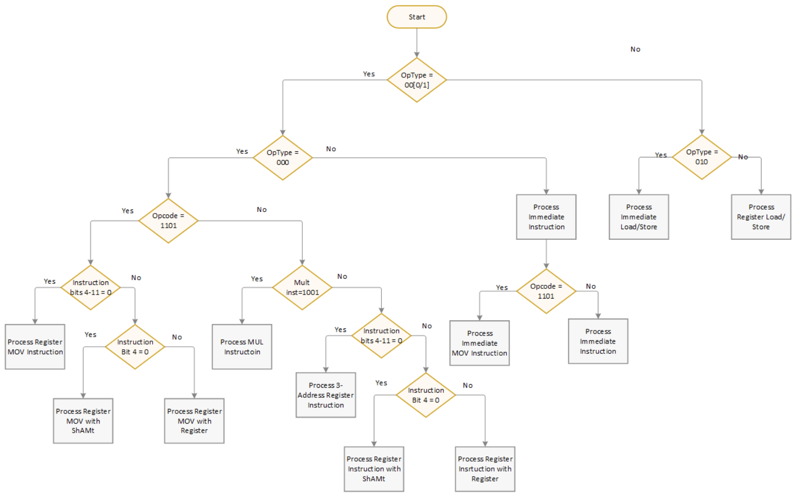
Figure 58: Flow chart to find instruction format
The textbook will now present two examples that utilize the flowchart to determine the instruction format. In both examples, the author will walk the reader through the process of navigating the flowchart with text and with an annotated flowchart.
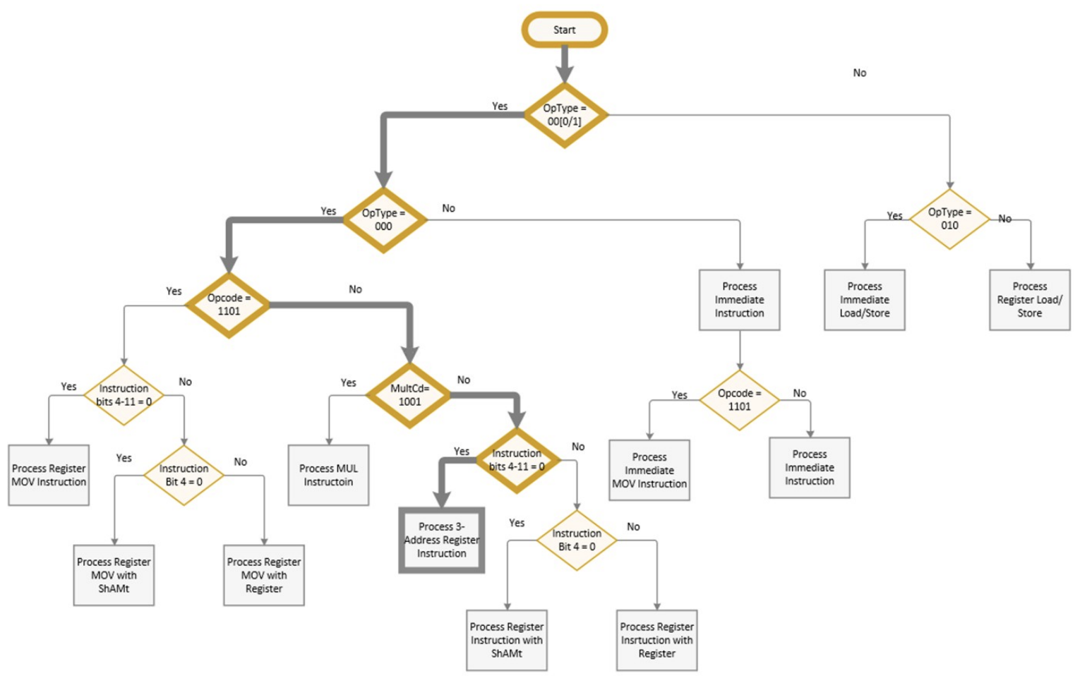
To use this chart, start with a machine code instruction, such as 0xe0821003. First, convert the instruction to binary, 0b1110 0000 1000 0010 0001 0000 0000 0011. Next, break out the OpType field, which is 0b000. This indicates it is a data operation, so take the left leg of the flow chart, and since the lowest order bit is 0 it is a register and check the OpCode. The OpCode is not 0b1101, so take the right leg of the flow chart. The MultCd is not 1001, so the instruction must be a register instruction. Since bits 4-11 are 0, the operand2 is simply Rm and a 3-address register instruction will be processed.
The register instruction is the following format:

Figure 59: Machine Code format with bits filled in
Filling in the bits, an OpCode of 0b0100 is an add instruction, and the registers are Rn = 2, Rd = 1, and Rm = 3. Thus, this corresponds to the assembly instruction:
ADD r1, r2, r3
To check this, compile this assembly code statement and run objdump to see if the original machine code is returned.
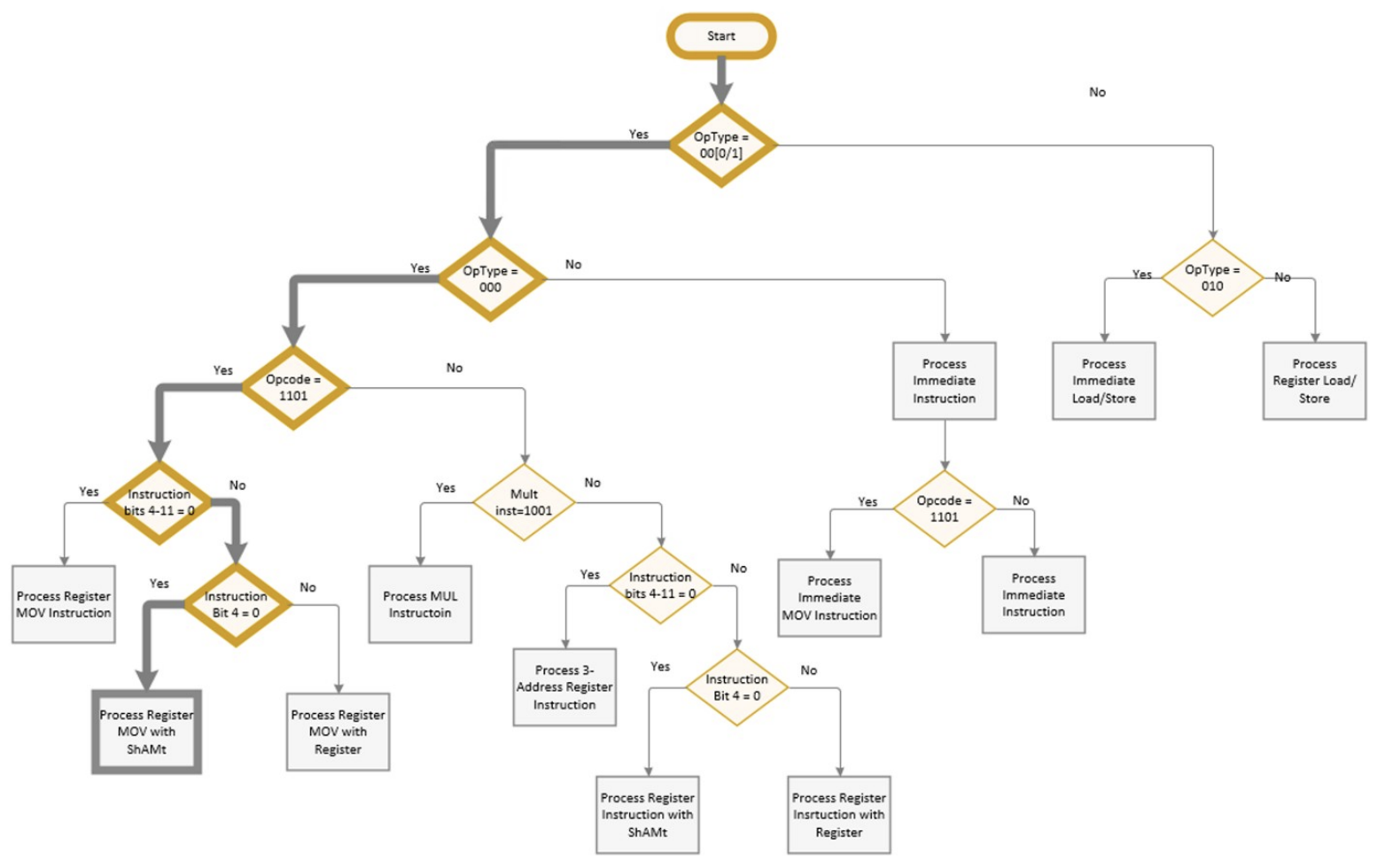
Another example is 0xe1a01182. First, convert the instruction to binary, 0b1110 0001 1010 0000 0001 0001 1000 0010. Next break out the OpType field, which is 0b000. This indicates it is a data operation, so take the left leg of the flow chart. The least significant bit is a 0, so take the left leg, and check the OpCode. The OpCode is 0b1101, so take the left leg of the flow chart. The instruction bits 4-11 are not 0, so it is a MOV operation with an Operand2 value. Bit 4 is a 0, so it is a shift with a ShAmt value.
The register instruction is the following format:

Figure 60: Machine Code format with bits filled in
A ShiftType of 0b000 is an LSL instruction, and the registers are Rm = 2, Rd = 1, and the ShAmt = 2. Thus, this corresponds to the assembly instruction:
MOV r1, r2, lsl #3
Since all register moves have equivalent shift operations, this is also the following:
LSL r1, r2, #3
Most readers will realize that the computer is not following a flow chart to determine the format for the operation, as a flow chart would require a synchronous circuit. Instead, the computer will simply determine the bits in the original instruction it needs to specify the instruction and compare those bits with the original instruction. Since all the compare operations for the formats can be run in parallel, this is a very fast way to determine the instruction format in the processor. This is shown in the following diagram. For the register ADD operation, this bit-mask is 0x00800000, and for the immediate shift LSL it is 0x01a00010.
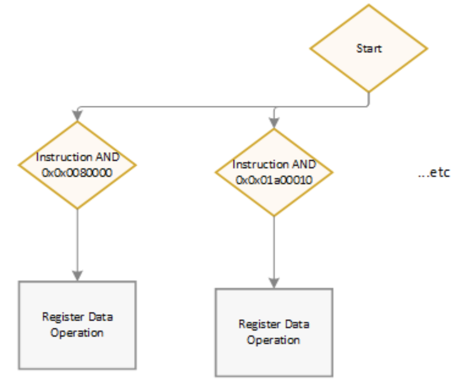
Figure 61: Computer selection of instruction format
Note that while using compare is fast for a computer, it is more confusing for the reader who is likely a person, and the flow chart is probably an easier way to decode the instruction for most readers.