
4.2: Stress, Force and Torque in Periodic Systems
- Page ID
- 28139

The configurations shown in Fig. 4.2.1 typify devices exploiting force or torque producing inter-actions between spatially periodic excitations on a "stator" structure and spatially periodic con-strained or induced sources on a "rotor." In each of these, the interaction is across an air gap, aregion having the electromagnetic characteristics of free space. The planar configuration of Fig. 4.2.1a might represent a linear motor or generator with the relevant force between "stator" (above)and "rotor" (below) z-directed, or it might be a developed model for the cylindrical geometry of Fig. 4.2.1c (appropriate in the limit where the air-gap spacing is small compared to the radius of the rotor). Figure 4.2.1b shows the cross section of either a planar "slab" with the interaction across two air gaps, or a cylindrical structure having an annular air gap. In either case the relevant net force is z-directed.
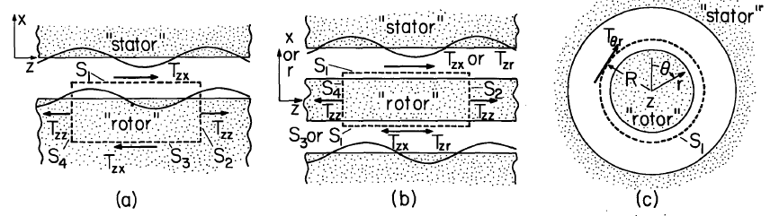
The total force acting in the z-direction on the "rotor" of Fig. 4.2.1a is conveniently determined by integrating the Maxwell stress, in accordance with Eq. 3.9.4, over the surface \(S\) enclosing a portion of the rotor having one fundamental length of periodicity. The portion \(S_1\) of this surface is at an arbitrary plane x = constant in the air gap. Because the fields and hence the stress components \(T_{zz}\) are periodic in \(z\), the contributions to the integration of the stress over surfaces \(S_2\) and \(S_4\) cancel regardless of where \(S_1\) is located in the air gap. The contribution to the integration over \(S_3\) can vanish for several reasons. The rotor may be perfectly permeable, of infinite permittivity or in-finitely conducting, in which case \(\overrightarrow{H}\) or \(\overrightarrow{E}\) is zero on \(S_3\). In Cartesian coordinates, the fields associated with excitations that are periodic in the z-direction decay in the x direction and if \(S_3\) is well removed from the air gap, the contribution on \(S_3\) asymptotically vanishes. Yet another possibility is that the planar model really is a developed model for the cylindrical configuration of Fig. 4.2.1c in which case the surface \(S\) is "pie" shaped and the section \(S_3\) does not exist. In any of these cases the z-directed force acting on the rotor of Fig. 4.2.1a is simply
\[ f_z = A \Big \langle T_{zx} \Big \rangle _z \Big |_{S_1} \label{1} \]
where \(A\) is the y-z area of the air gap and \(T_{zx }\) is the magnetic or electric stress tensor, as the case may be. The brackets indicate a spatial average is taken, as discussed in Sec. 2.15.
There is no question as to which of the stress tensors in Table 3.10.1 should be used. As discussed in Sec. 3.10, in the free-space region of the air gap, all of the magnetic and all of the electric stress tensors agree.
If Fig. 4.2.1b represents a planar layer, then there are stress contributions from surfaces \(S_1\) and \(S_3\), and the net force acting on a section of the layer having area \(A\) in the y-z plane is
\[ f_z = A [ \Big \langle T_{zx} \Big \rangle _z \Big |_{S_1} - \Big \langle T_{zx} \Big \rangle _z \Big |_{S_3}] \label{2} \]
On the other hand, if the "rotor" in that figure is a cylinder, then the net force takes the form of Equation \ref{1}, with \(A\) the area of an enclosing cylindrical surface and appropriate shear stress \(T_{zx} \rightarrow T_{zr}\) evaluated on that surface.
In computing the net torque on the rotor of Fig. 4.2.1c, it is tempting to multiply the space average shear stress \(\big \langle T_{\theta r} \big \rangle _{\theta}\) by the lever arm \(R\) and the area \(A\) of a cylindrical enclosing surface having radius \(R\):
\[ \tau_z = RA \Big \langle T_{\theta r} \Big \rangle _{\theta} \Big |_{S_1} \label{3} \]
Because the stress is symmetric, this notion is rigorous, as can be seen by applying Eq. 3.9.16 to the surface \(S_1\) of Fig. 4.2.1c.