
1.1: Coordinate Systems
- Page ID
- 48112
\( \newcommand{\vecs}[1]{\overset { \scriptstyle \rightharpoonup} {\mathbf{#1}} } \)
\( \newcommand{\vecd}[1]{\overset{-\!-\!\rightharpoonup}{\vphantom{a}\smash {#1}}} \)
\( \newcommand{\dsum}{\displaystyle\sum\limits} \)
\( \newcommand{\dint}{\displaystyle\int\limits} \)
\( \newcommand{\dlim}{\displaystyle\lim\limits} \)
\( \newcommand{\id}{\mathrm{id}}\) \( \newcommand{\Span}{\mathrm{span}}\)
( \newcommand{\kernel}{\mathrm{null}\,}\) \( \newcommand{\range}{\mathrm{range}\,}\)
\( \newcommand{\RealPart}{\mathrm{Re}}\) \( \newcommand{\ImaginaryPart}{\mathrm{Im}}\)
\( \newcommand{\Argument}{\mathrm{Arg}}\) \( \newcommand{\norm}[1]{\| #1 \|}\)
\( \newcommand{\inner}[2]{\langle #1, #2 \rangle}\)
\( \newcommand{\Span}{\mathrm{span}}\)
\( \newcommand{\id}{\mathrm{id}}\)
\( \newcommand{\Span}{\mathrm{span}}\)
\( \newcommand{\kernel}{\mathrm{null}\,}\)
\( \newcommand{\range}{\mathrm{range}\,}\)
\( \newcommand{\RealPart}{\mathrm{Re}}\)
\( \newcommand{\ImaginaryPart}{\mathrm{Im}}\)
\( \newcommand{\Argument}{\mathrm{Arg}}\)
\( \newcommand{\norm}[1]{\| #1 \|}\)
\( \newcommand{\inner}[2]{\langle #1, #2 \rangle}\)
\( \newcommand{\Span}{\mathrm{span}}\) \( \newcommand{\AA}{\unicode[.8,0]{x212B}}\)
\( \newcommand{\vectorA}[1]{\vec{#1}} % arrow\)
\( \newcommand{\vectorAt}[1]{\vec{\text{#1}}} % arrow\)
\( \newcommand{\vectorB}[1]{\overset { \scriptstyle \rightharpoonup} {\mathbf{#1}} } \)
\( \newcommand{\vectorC}[1]{\textbf{#1}} \)
\( \newcommand{\vectorD}[1]{\overrightarrow{#1}} \)
\( \newcommand{\vectorDt}[1]{\overrightarrow{\text{#1}}} \)
\( \newcommand{\vectE}[1]{\overset{-\!-\!\rightharpoonup}{\vphantom{a}\smash{\mathbf {#1}}}} \)
\( \newcommand{\vecs}[1]{\overset { \scriptstyle \rightharpoonup} {\mathbf{#1}} } \)
\(\newcommand{\longvect}{\overrightarrow}\)
\( \newcommand{\vecd}[1]{\overset{-\!-\!\rightharpoonup}{\vphantom{a}\smash {#1}}} \)
\(\newcommand{\avec}{\mathbf a}\) \(\newcommand{\bvec}{\mathbf b}\) \(\newcommand{\cvec}{\mathbf c}\) \(\newcommand{\dvec}{\mathbf d}\) \(\newcommand{\dtil}{\widetilde{\mathbf d}}\) \(\newcommand{\evec}{\mathbf e}\) \(\newcommand{\fvec}{\mathbf f}\) \(\newcommand{\nvec}{\mathbf n}\) \(\newcommand{\pvec}{\mathbf p}\) \(\newcommand{\qvec}{\mathbf q}\) \(\newcommand{\svec}{\mathbf s}\) \(\newcommand{\tvec}{\mathbf t}\) \(\newcommand{\uvec}{\mathbf u}\) \(\newcommand{\vvec}{\mathbf v}\) \(\newcommand{\wvec}{\mathbf w}\) \(\newcommand{\xvec}{\mathbf x}\) \(\newcommand{\yvec}{\mathbf y}\) \(\newcommand{\zvec}{\mathbf z}\) \(\newcommand{\rvec}{\mathbf r}\) \(\newcommand{\mvec}{\mathbf m}\) \(\newcommand{\zerovec}{\mathbf 0}\) \(\newcommand{\onevec}{\mathbf 1}\) \(\newcommand{\real}{\mathbb R}\) \(\newcommand{\twovec}[2]{\left[\begin{array}{r}#1 \\ #2 \end{array}\right]}\) \(\newcommand{\ctwovec}[2]{\left[\begin{array}{c}#1 \\ #2 \end{array}\right]}\) \(\newcommand{\threevec}[3]{\left[\begin{array}{r}#1 \\ #2 \\ #3 \end{array}\right]}\) \(\newcommand{\cthreevec}[3]{\left[\begin{array}{c}#1 \\ #2 \\ #3 \end{array}\right]}\) \(\newcommand{\fourvec}[4]{\left[\begin{array}{r}#1 \\ #2 \\ #3 \\ #4 \end{array}\right]}\) \(\newcommand{\cfourvec}[4]{\left[\begin{array}{c}#1 \\ #2 \\ #3 \\ #4 \end{array}\right]}\) \(\newcommand{\fivevec}[5]{\left[\begin{array}{r}#1 \\ #2 \\ #3 \\ #4 \\ #5 \\ \end{array}\right]}\) \(\newcommand{\cfivevec}[5]{\left[\begin{array}{c}#1 \\ #2 \\ #3 \\ #4 \\ #5 \\ \end{array}\right]}\) \(\newcommand{\mattwo}[4]{\left[\begin{array}{rr}#1 \amp #2 \\ #3 \amp #4 \\ \end{array}\right]}\) \(\newcommand{\laspan}[1]{\text{Span}\{#1\}}\) \(\newcommand{\bcal}{\cal B}\) \(\newcommand{\ccal}{\cal C}\) \(\newcommand{\scal}{\cal S}\) \(\newcommand{\wcal}{\cal W}\) \(\newcommand{\ecal}{\cal E}\) \(\newcommand{\coords}[2]{\left\{#1\right\}_{#2}}\) \(\newcommand{\gray}[1]{\color{gray}{#1}}\) \(\newcommand{\lgray}[1]{\color{lightgray}{#1}}\) \(\newcommand{\rank}{\operatorname{rank}}\) \(\newcommand{\row}{\text{Row}}\) \(\newcommand{\col}{\text{Col}}\) \(\renewcommand{\row}{\text{Row}}\) \(\newcommand{\nul}{\text{Nul}}\) \(\newcommand{\var}{\text{Var}}\) \(\newcommand{\corr}{\text{corr}}\) \(\newcommand{\len}[1]{\left|#1\right|}\) \(\newcommand{\bbar}{\overline{\bvec}}\) \(\newcommand{\bhat}{\widehat{\bvec}}\) \(\newcommand{\bperp}{\bvec^\perp}\) \(\newcommand{\xhat}{\widehat{\xvec}}\) \(\newcommand{\vhat}{\widehat{\vvec}}\) \(\newcommand{\uhat}{\widehat{\uvec}}\) \(\newcommand{\what}{\widehat{\wvec}}\) \(\newcommand{\Sighat}{\widehat{\Sigma}}\) \(\newcommand{\lt}{<}\) \(\newcommand{\gt}{>}\) \(\newcommand{\amp}{&}\) \(\definecolor{fillinmathshade}{gray}{0.9}\)A coordinate system is a way of uniquely specifying the location of any position in space with respect to a reference origin. Any point is defined by the intersection of three mutually perpendicular surfaces. The coordinate axes are then defined by the normals to these surfaces at the point. Of course the solution to any Problem is always independent of the choice of coordinate system used, but by taking advantage of symmetry, computation can often be simplified by proper choice of coordinate description. In this text we only use the familiar rectangular (Cartesian), circular cylindrical, and spherical coordinate systems.
Rectangular (Cartesian) Coordinates
The most common and often preferred coordinate system is defined by the intersection of three mutually perpendicular planes as shown in Figure 1-la. Lines parallel to the lines of intersection between planes define the coordinate axes (x, y, z), where the x axis lies perpendicular to the plane of constant x, the y axis is perpendicular to the plane of constant y, and the z axis is perpendicular to the plane of constant z. Once an origin is selected with coordinate (0, 0, 0), any other point in the plane is found by specifying its x-directed, y directed, and z-directed distances from this origin as shown for the coordinate points located in Figure 1-1b.
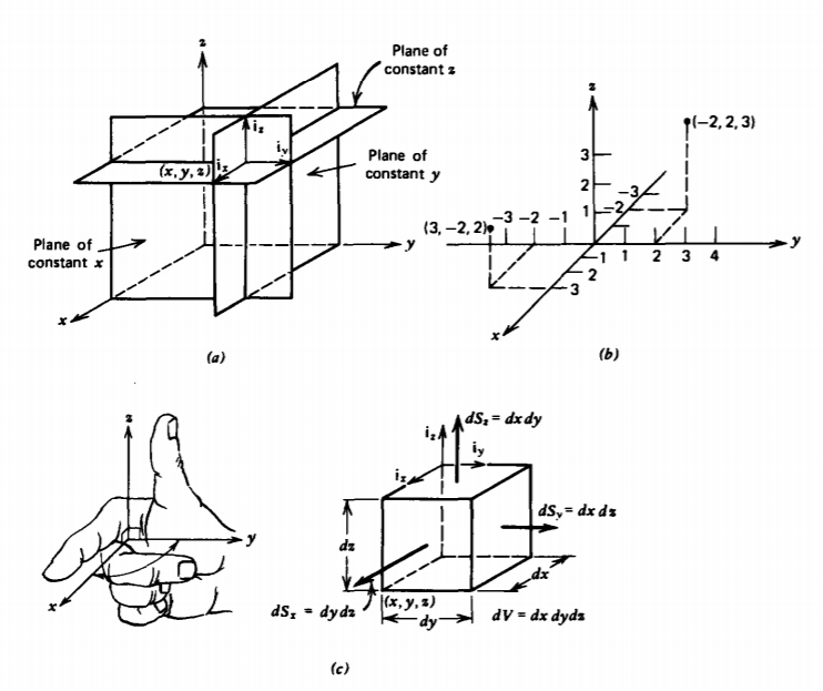
By convention, a right-handed coordinate system is always used whereby one curls the fingers of his or her right hand in the direction from x to y so that the forefinger is in the x direction and the middle finger is in the y direction. The thumb then points in the z direction. This convention is necessary to remove directional ambiguities in theorems to be derived later.
Coordinate directions are represented by unit vectors ix, iy, and iz, each of which has a unit length and points in the direction along one of the coordinate axes. Rectangular coordinates are often the simplest to use because the unit vectors always point in the same direction and do not change direction from point to point.
A rectangular differential volume is formed when one moves from a point (x, y, z) by an incremental distance dx, dy, and dz in each of the three coordinate directions as shown in Figure 1-1c. To distinguish surface elements we subscript the area element of each face with the coordinate perpendicular to the surface.
Circular Cylindrical Coordinates
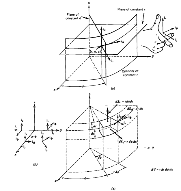
The cylindrical coordinate system is convenient to use when there is a line of symmetry that is defined as the z axis. As shown in Figure 1-2a, any point in space is defined by the intersection of the three perpendicular surfaces of a circular cylinder of radius r, a plane at constant z, and a plane at constant angle \(\phi\) from the x axis.
The unit vectors ir, i\(\phi\), and ix are perpendicular to each of these surfaces. The direction of ix is independent of position, but unlike the rectangular unit vectors the direction of ir and i\(\phi\) change with the angle \(\phi\) as illustrated in Figure 1-2b. For instance, when \(\phi\) = 0 then ir = ix, and i\(\phi\) = iy, while if \(\phi = \pi/2\), then ir = iy and i\(\phi\) = -ix.
By convention, the triplet (r, \(\phi\), z) must form a righthanded coordinate system so that curling the fingers of the right hand from ir to i\(\phi\) puts the thumb in the z direction.
A section of differential size cylindrical volume, shown in Figure 1-2c, is formed when one moves from a point at coordinate (r, \(\phi\), z) by an incremental distance dr, r d\(\phi\), and dz in each of the three coordinate directions. The differential volume and surface areas now depend on the coordinate r as summarized in Table 1-1.
| CARTESIAN | CYLINDRICAL | SPHERICAL |
|---|---|---|
| \(\textbf{dl} = dx \: \textbf{i}_{x} + dy \: \textbf{i}_{y} dz \: \textbf{i}_{z}\) | \(\textbf{dl} = d \textrm{r} \: \textbf{i}_{\textrm{r}} + \textrm{r} \: d \phi \: \textbf{i}_{\phi} + dz \: \textbf{i}_{z}\) | \( \textbf{dl} = dr \: \textbf{i}_{r} + r d \theta \: \textbf{i}_{\theta} + r \sin \theta d \phi \: \textbf{i}_{\phi}\) |
| \(dS_{x} = dy dz\) | \(dS_{r} = \textrm{r} d \phi d z\) | \(dS_{r} = r^{2} \sin \theta d \theta d \phi\) |
| \(dS_{y} = dx \: dz\) | \(dS_{\phi} = d \textrm{r} \: d z\) | \(dS_{\theta} = r \sin \theta dr \: d \phi\) |
| \(dS_{z} = dx \: dy\) | \(dS_{z} = \textrm{r} \: d \textrm{r} \: d \phi\) | \(dS_{\phi} = r \: dr \: d \theta\) |
| \(dV = dx \: dy \: dz\) | \(dV = \textrm{r} d \textrm{r} \: d \phi \: dz\) | \(dV = r^{2} \sin \theta \: dr \: d \theta \: d \phi\) |
Spherical Coordinates
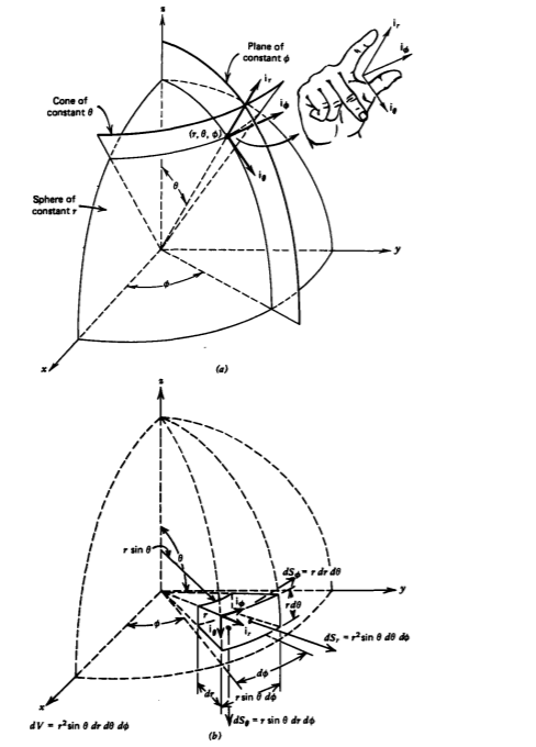
A spherical coordinate system is useful when there is a point of symmetry that is taken as the origin. In Figure 1-3a we see that the spherical coordinate (r, \(\theta\), \(\phi\)) is obtained by the intersection of a sphere with radius r, a plane at constant.
angle \(\phi\) from the x axis as defined for the cylindrical coordinate system, and a cone at angle \(\theta\) from the z axis. The unit vectors ir, i\(\theta\), and i\)\phi\) are perpendicular to each of these surfaces and change direction from point to point. The triplet (r, \(\theta\), \(\phi\)) must form a right-handed set of coordinates. The differential-size spherical volume element formed by considering incremental displacements dr, rd\(\theta\), r sin \(\theta\) d \(\phi\)
| CARTESIAN | CYLINDRICAL | SPHERICAL |
| x = | r cos \(\phi\) | \(r \: \sin \theta \: \cos \phi\) |
| y = | r sin \(\phi\) | \(r \: sin \theta \: \sin \phi\) |
| z = | z | \(r \: cos \: \(\theta\) \) |
| ix = | cos \(\phi\) ir - sin \(\phi\) i\(\phi\) | \(\sin \: \theta \: \cos \: \phi \: \textbf{i}_{r} + \cos \: \theta \: \cos \: \phi \: \textbf{i}_{\theta} = \sin \: \phi \: \textbf{i}_{\phi}\) |
| iy = | sin \(\phi\) ir + cos \(\phi\) i\(\phi\) | \(\sin \: \theta \: \sin \: \phi \: \textbf{i}_{r} + \cos \: \theta \: \sin \phi \: \textbf{i}_{\theta} + \: \cos \: \phi \: \textbf{i}_{\phi}\) |
| iz = | iz |
| CYLINDRICAL | CARTESIAN | SPHERICAL |
| r = | \(\sqrt{x^{2} + y^{2}}\) | \(r \sin \theta\) |
| \(\phi\) = | \(\tan^{-1} \frac{y}{x}\) | \(\phi\) |
| z = | z | \(r cos \(\theta\) |
| ir = | \(\cos \: \phi \: \textbf{i}_{x} + \sin \: \phi \: \textbf{i}_{y}\) | \(\sin \: \theta \: \textbf{i}_{r} + \cos \: \theta \: \textbf{i}_{\theta}\) |
| i\(\phi\) |
\(-sin \: \phi \: \textbf{i}_{x} + cos \: \phi\) \: \textbf{i}_{y}\) |
i\(\phi\) |
| iz = | iz | \(\cos \: \theta \: \textbf{i}_{r} - \sin \: \theta \: \textbf{i}_{\theta}\) |
\(r \: sin \theta \: \sin \phi\)
\(\sin \theta \cos \phi \textbf{i}_{r} + \cos \theta \: \cos \phi \textbf{i}_{\theta} = \sin \phi \textbf{i}_{\phi}\)
CYLINDRICAL CARTESIAN SPHERICAL \(\phi\) = \(\tan^{-1} \frac{y}{x}\) = \(\phi\) z =z = \(r \: \cos \theta\) ir = \(\cos \: \phi \textbf{i}_{x} + \sin \: \phi \textbf{i}_{y}\) = \(\sin \: \theta \textbf{i}_{r} + \cos \: \theta \textbf{i}_{\theta}\) i\(\phi\) = \(\textbf{i}_{\phi}\)
| SPHERICAL | CARTESIAN | CYLINDRICAL |
|---|---|---|
| r = | \(\sqrt{x^{2} + y^{2} + z^{2}}\) = | \(\sqrt{r^{2} + z^{2}}\) |
| \(\theta\) = | \(\cos^{-1} \frac{z}{\sqrt{x^{2} + y^{2} + z^{2}}}\) = | \(\cos^{-1} \frac{z}{\sqrt{r^{2} + z^{2}}}\) |
| \(\phi\) = | \(\cot^{-1} \frac{x}{y}\) = | \(\phi\) |
| ir = | \(\sin \: \theta \: \cos \phi \textbf{i}_{x} + \sin \: \theta \: \sin \: \phi \textbf{i}_{y} + \cos \: \theta \textbf{i}_{x}\) = | \(\sin \: \theta \textbf{i}_{r} + \cos \: \theta \textbf{i}_{x}\) |
| i\(\theta\) = | \(\cos \: \theta \: \cos \phi \textbf{i}_{x} + \cos \: \theta \: \sin \: \phi \textbf{i}_{y} = \sin \: \theta \textbf{i}_{x}\) = | \(\sin \: \theta \textbf{i}_{r} + \cos \theta \textbf{i}_{x}\) |
| i\(\phi\) = | i\(\phi\) |
* Note that throughout this text a lower case roman r is used for the cylindrical radial coordinate while an italicized r is used for the spherical radial coordinate.
from the coordinate (r, \(\theta\), \(\phi\)) now depends on the angle \(\theta\) and the radial position r as shown in Figure 1-3b and summarized in Table 1-1. Table 1-2 summarizes the geometric relations between coordinates and unit vectors for the three coordinate systems considered. Using this table, it is possible to convert coordinate positions and unit vectors from one system to another.