
1.1: Network Primitives
- Page ID
- 55506

Electric network theory deals with two primitive quantities, which we will refer to as:
- Potential (or voltage), and
- Current.
Current is the actual flow of charged carriers, while difference in potential is the force that causes that flow. As we will see, potential is a single- valued function that may be uniquely defined over the nodes of a network. Current, on the other hand, flows through the branches of the network. Figure 1 shows the basic notion of a branch, in which a voltage is defined across the branch and a current is defined to flow through the branch. A network is a collection of such elements, connected together by wires.
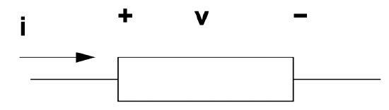 Figure 1: Basic Circuit Element
Network topology is the interconnection of its elements. That, plus the constraints on voltage and current imposed by the elements themselves, determines the performance of the network, described by the distribution of voltages and currents throughout the network.
Two important concepts must be described initially. These are of “loop” and “node”.
- A loop in the network is any closed path through two or more elements of the network. Any non-trivial network will have at least one such loop.
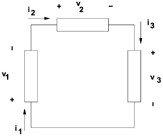 Figure 2: This is a loop
- a node is a point at which two or more elements are interconnected.
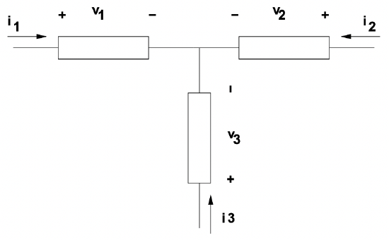 Figure 3: This is a node
The two fundamental laws of network theory are known as Kirchoff’s Voltage Law (KVL), and Kirchoff’s Current Law (KCL). These laws describe the topology of the network, and arise directly from the fundmantal laws of electromagnetics. They are simply stated as:
- \(\ \sum_{l o o p} v_{k}=0 \label{1}\)
- \(\ \sum_{n o d e} i_{k}=0\label{2}\)
1Note that KVL is a discrete version of Faraday’s Law, valid to the extent that no time-varying flux links the loop. KCL is just conservation of current, allowing for no accumulation of charge at the node.
Network elements affect voltages and currents in one of three ways:
- Voltage sources constrain the potential difference across their terminals to be of some fixed value (the value of the source).
- Current sources constrain the current through the branch to be of some fixed value.
- All other elements impose some sort of relationship, either linear or nonlinear, between voltage across and current through the branch.
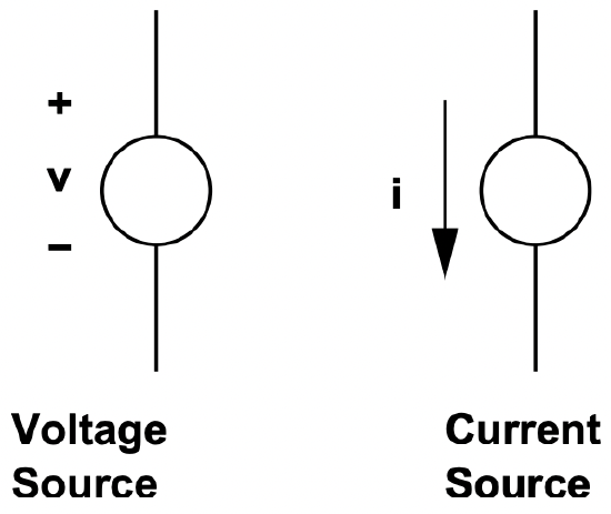 Figure 4: Notation for voltage and current sources
Voltage and current sources can be either independent or dependent. Independent sources have values which are, as the name implies, independent of other variables in a circuit. Dependent sources have values which depend on some other variable in a circuit. A common example of a dependent source is the equivalent current source used for modeling the collector junction in a transistor. Typically, this is modeled as a current dependent current source, in which collector current is taken to be directly dependent on emitter current. Such dependent sources must be handled with some care, for certain tricks we will be discussing below do not work with them.
For the present time, we will consider, in addition to voltage and current sources, only impedance elements, which impose a linear relationship between voltage and current. The most common of these is the resistance, which imposes the relationship which is often referred to as Ohm’s law:
\(\ v_{r}=R i_{r}\label{3}\)
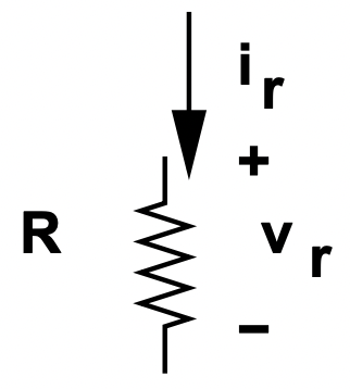 Figure 5: Resistance Circuit Element
A bit later on in this note, we will extend this notion of impedance to other elements, but for the moment the resistance will serve our purposes.