
4.3: Unbalanced Sources
- Page ID
- 55577

Consider the network shown in Figure 4. A balanced three-phase resistor is fed by a balanced line (with mutual coupling between phases). Assume that only one phase of the voltage source is working, so that:
\[\ \underline{V}_{a}=V\label{46} \]
\[\ \underline{V}_{b}=0\label{47} \]
\[\ \underline{V}_{c}=0\label{48} \]
The objective of this example is to find currents in the three phases.
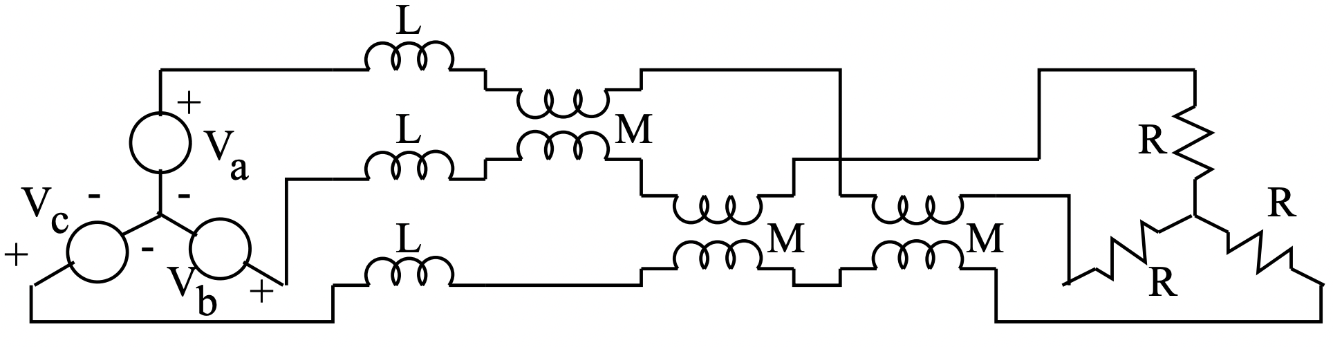 Figure 4: Balanced Load, Balanced Line, Unbalanced Source
To start, note that the unbalanced voltage source has the following set of symmetrical components:
\[\ \underline{V}_{1}=\frac{V}{3}\label{49} \]
\[\ \underline{V}_{2}=\frac{V}{3}\label{50} \]
\[\ \underline{V}_{0}=\frac{V}{3}\label{51} \]
Next, the network facing the source consists of the line, with impedances:
\[\ \underline{Z}_{1}=j \omega(L-M)\label{52} \]
\[\ \underline{Z}_{2}=j \omega(L-M)\label{53} \]
\[\ \underline{Z}_{0}=j \omega(L+2 M)\label{54} \]
and the three- phase resistor has impedances:
\[\ \underline{Z}_{1}=R\label{55} \]
\[\ \underline{Z}_{2}=R\label{56} \]
\[\ \underline{Z}_{0}=\infty\label{57} \]
Note that the impedance to zero sequence is infinite because the neutral is not connected back to the neutral of the voltage source. Thus the sum of line currents must always be zero and this in turn precludes any zero sequence current. The problem is thus described by the networks which appear in Figure 5.
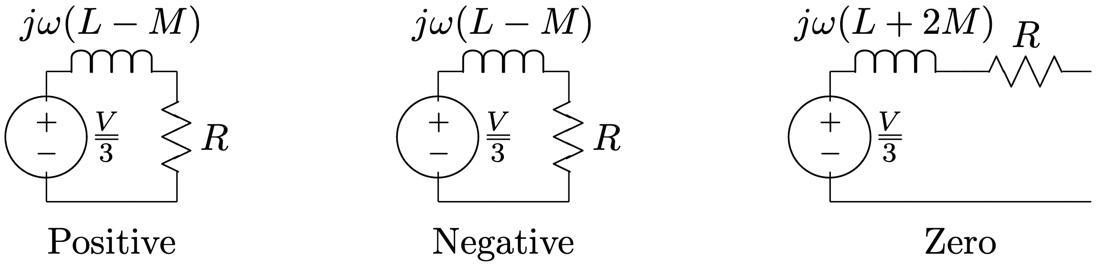 Figure 5: Sequence Networks
Currents are:
\(\ \begin{array}{l}
\underline{I}_{1}=\frac{V}{3(j \omega(L-M)+R)} \\
\underline{I}_{2}=\frac{V}{3(j \omega(L-M)+R)} \\
\underline{I}_{0}=0
\end{array}\)
Phase currents may now be re-assembled:
\(\ \begin{aligned}
\underline{I}_{a} &=\underline{I}_{1}+\underline{I}_{2}+\underline{I}_{0} \\
\underline{I}_{b} &=\underline{a}^{2} \underline{I}_{1}+\underline{a} \underline{I}_{2}+\underline{I}_{0} \\
\underline{I}_{c} &=\underline{aI}_{1}+\underline{a}^{2} \underline{I}_{2}+\underline{I}_{0}
\end{aligned}\)
or:
\(\ \begin{aligned}
\underline{I}_{a}&=\frac{2 V}{3(j \omega(L-M)+R)} \\
\underline{I}_{b}&=\frac{\left(\underline{a}^{2}+\underline{a}\right) V}{3(j \omega(L-M)+R)}\\
&=\frac{-V}{3(j \omega(L-M)+R)} \\
\underline{I}_{c} &=\frac{\left(\underline{a}+\underline{a}^{2}\right) V}{3(j \omega(L-M)+R)} \\
&=\frac{-V}{3(j \omega(L-M)+R)}
\end{aligned}\)
(Note that we have used \(\ \underline{a}^{2}+\underline{a}=-1\)).