
6.3: Faraday’s Law and Inductance
- Page ID
- 55592

Changing magnetic fields give rise to electric fields and consequently produce voltage. This is how inductance works. Consider the situation shown rather abstractly in Figure 5.
Faraday’s Law is, in integral form:
\(\ \oint \vec{E} \cdot d \ell=-\frac{d}{d t} \iint \ _\text { Area } \vec{B} \cdot \vec{n} d a\)
If the contour shown is highly conducting (say, if it is a wire), there is zero electric field over that part of the contour. Voltage across the terminals is:
\(\ V_{a b}=\int_{a}^{b} \vec{E} \cdot d \ell\)
and that is the whole of the integral above. Thus we may conclude that:
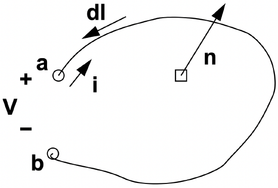 Figure 5: Loop for Faraday’s Law
\(\ V_{a b}=-\frac{d}{d t} \iint \ _\text { Area } \vec{B} \cdot \vec{n} d a\)
Now, if we define flux linked by this contour to be:
\(\ \lambda=-\iint \ _\text{Area} \vec{B} \cdot \vec{n} d a\)
then voltage is, as we expect:
\(\ V_{a b}=\frac{d \lambda}{d t}\)
As it turns out, current flowing in the wire with sense shown by i in Figure 5 tends to produce flux with sense opposite to the normal vector shown in that figure, and so produces positive flux. Generally, in calculating inductance, one uses the ’right hand rule’ in determing the direction of flux linkage: if the fingers of your right hand follow the direction of the winding, from the positive terminal, positive flux is in the direction of your thumb.
Example: Solenoid Actuator
Shown in Figure 6 is a representation of a common solenoid actuator. When current is put through the coil a magnetic flux appears in the gaps and pulls the plunger to the left. We will examine the force and how to calculate it in later chapters. For now, however, we are concerned with magnetic fields in the device and with the calculation of inductance. Assume that the stator and plunger are both made of highly permeable materials \(\ (\mu \rightarrow \infty)\). If the coil carries current \(\ I\) in \(\ N\) turns in the sense shown, magnetic flux will cross the narrow air-gap to the right in the direction from the stator to the plunger and then return in the sense shown in the variable length gap of width \(\ x\). It is clear that this is also positive sense flux for the coil.
The magnetic circuit equivalent is shown in Figure 7. All of the flux produced crosses the variable width gap which has reluctance:
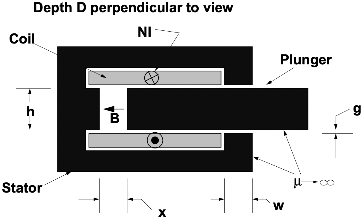 Figure 6: Cross-Section of Solenoid Actuator
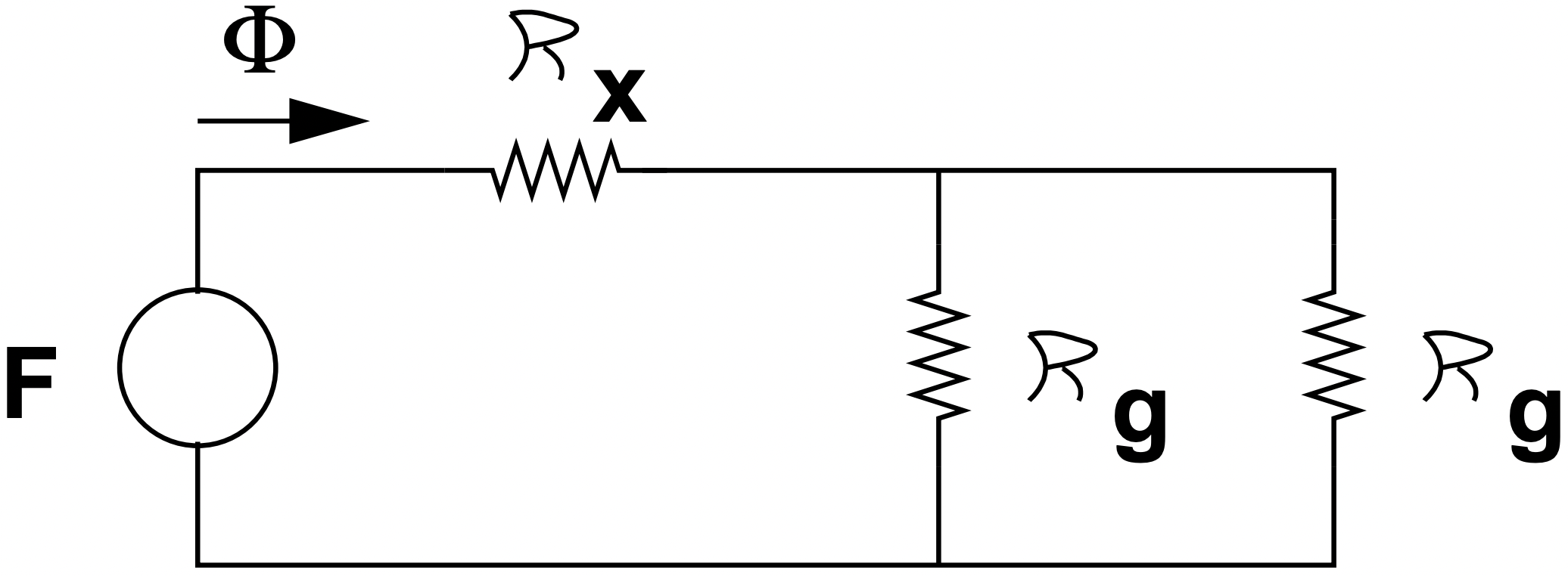 Figure 7: Magnetic Equivalent Circuit of Solenoid Actuator
\(\ \mathcal{R}_{x}=\frac{x}{\mu_{0} h D}\)
Half of the flux crosses each of the other two gaps, which are in parallel and have reluctance:
\(\ \mathcal{R}_{g}=\frac{g}{\mu_{0} w D}\)
Total flux in the magnetic circuit is
\(\ \Phi=\frac{F}{\mathcal{R}_{x}+\frac{1}{2} \mathcal{R}_{g}}\)
And since \(\ \lambda=N \Phi\) and \(\ F=N I\), the inductance of this structure is:
\(\ L=\frac{N^{2}}{\mathcal{R}}=\frac{N^{2}}{\mathcal{R}_{x}+\frac{1}{2} \mathcal{R}_{g}}\)