
12.1: Motor Morphologies
- Page ID
- 57497

There are, of course, many ways of building permanent magnet motors, but we will consider only a few in this note. Actually, once these are understood, rating evaluations of most other geometrical arrangements should be fairly straightforward. It should be understood that the “rotor inside” vs. “rotor outside” distinction is in fact trivial, with very few exceptions, which we will note.
Surface Magnet Machines
Figure 1 shows the basic magnetic morphology of the motor with magnets mounted on the surface of the rotor and an otherwise conventional stator winding. This sketch does not show some of the important mechanical aspects of the machine, such as the means for fastening the permanent magnets to the rotor, so one should look at it with a bit of caution. In addition, this sketch and the other sketches to follow are not necessarily to a scale that would result in workable machines.
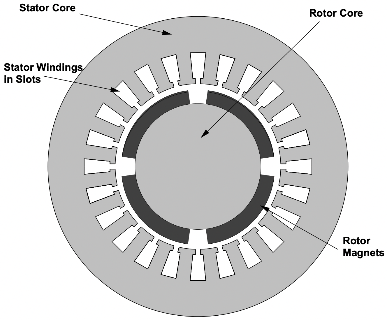 Figure 1: Axial View of a Surface Mount Motor
 This figure shows an axial section of a four-pole \(\ (p=2)\) machine. The four magnets are mounted on a cylindrical rotor “core”, or shaft, made of ferromagnetic material. Typically this would simply be a steel shaft. In some applications the magnets may be simply bonded to the steel. For applications in which a glue joint is not satisfactory (e.g. for high speed machines) some sort of rotor banding or retaining ring structure is required.
The stator winding of this machine is “conventional”, very much like that of an induction motor, consisting of wires located in slots in the surface of the stator core. The stator core itself is made of laminated ferromagnetic material (probably silicon iron sheets), the character and thickness of the sheets determined by operating frequency and efficiency requirements. They are required to carry alternating magnetic fields, so must be laminated to reduce eddy current losses.
This sort of machine is simple in construction. Note that the operating magnetic flux density in the air-gap is nearly the same as in the magnets, so that this sort of machine cannot have air-gap flux densities higher than that of the remanent flux density of the magnets. If low cost ferrite magnets are used, this means relatively low induction and consequently relatively low efficiency and power density. (Note the qualifier “relatively” here!). Note, however, that with modern, high performance permanent magnet materials in which remanent flux densities can be on the order of 1.2 T, air-gap working flux densities can be on the order of 1 T. With the requirement for slots to carry the armature current, this may be a practical limit for air-gap flux density anyway.
It is also important to note that the magnets in this design are really in the “air gap” of the machine, and therefore are exposed to all of the time- and space- harmonics of the stator winding MMF. Because some permanent magnets have electrical conductivity (particularly the higher performance magnets), any asynchronous fields will tend to produce eddy currents and consequent losses in the magnets.
Interior Magnet or Flux Concentrating Machines
Interior magnet designs have been developed to counter several apparent or real shortcomings of surface mount motors:
- Flux concentrating designs allow the flux density in the air-gap to be higher than the flux density in the magnets themselves.
- In interior magnet designs there is some degree of shielding of the magnets from high order space harmonic fields by the pole pieces.
- There are control advantages to some types of interior magnet motors, as we will show anon. Essentially, they have relatively large negative saliency which enhances “flux weakening” for high speed operation, in rather direct analogy the what is done in DC machines.
- Some types of internal magnet designs have (or claim) structural advantages over surface mount magnet designs.
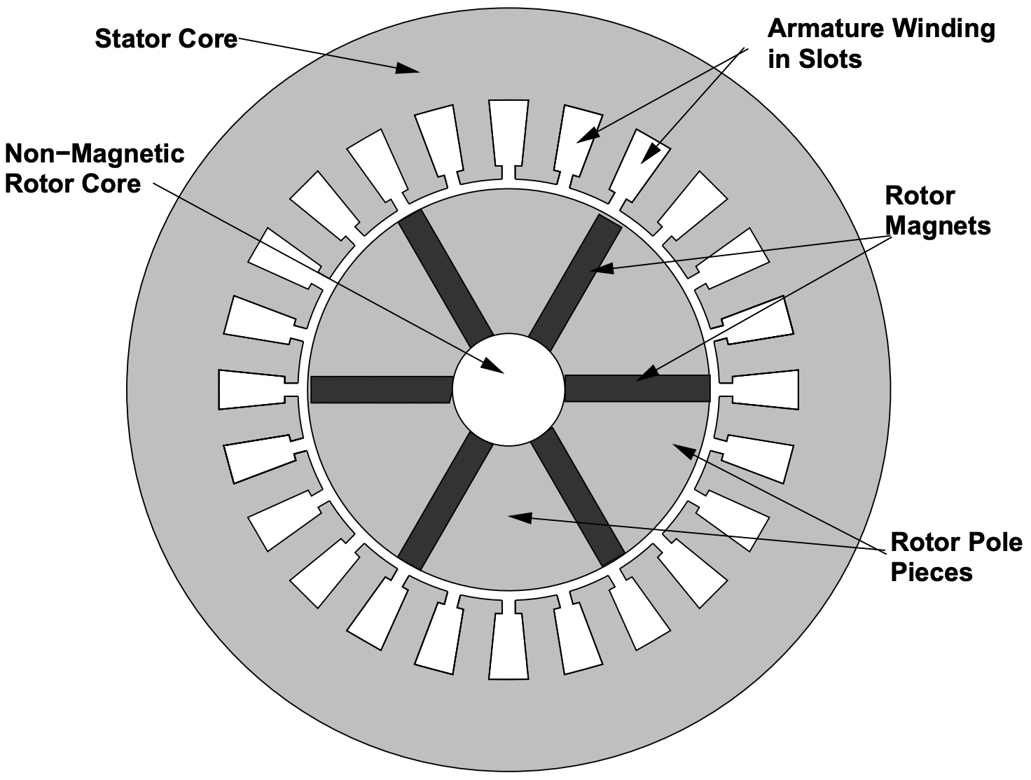 Figure 2: Axial View of a Flux Concentrating Motor
The geometry of one type of internal magnet motor is shown (crudely) in Figure 2. The permanent magnets are oriented so that their magnetization is azimuthal. They are located between wedges of magnetic material (the pole pieces) in the rotor. Flux passes through these wedges, going radially at the air- gap, then azimuthally through the magnets. The central core of the rotor must be non-magnetic, to prevent “shorting out” the magnets. No structure is shown at all in this drawing, but quite obviously this sort of rotor is a structural challenge. Shown is a six-pole machine. Typically, one does not expect flux concentrating machines to have small pole numbers, because it is difficult to get more area inside the rotor than around the periphery. On the other hand, a machine built in this way but without substantial flux concentration will still have saliency and magnet shielding properties.
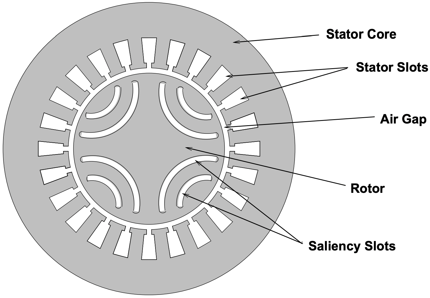 Figure 3: Axial View of Internal Magnet Motor
A second morphology for an internal magneti motor is shown in Figure 3. This geometry has been proposed for highly salient synchronous machines without permanent magnets: such machines would run on the saliency torque and are called synchronous reluctance motors. however, the saliency slots may be filled with permanent magnet material, giving them some internally generated flux as well. The rotor iron tends to short out the magnets, so that the ’bridges’ around the ends of the permanent magnets must be relatively thin. They are normally saturated.
At first sight, these machines appear to be quite complicated to analyze, and that judgement seems to hold up.
Air Gap Armature Windings
Shown in Figure 4 is a surface-mounted magnet machine with an air-gap, or surface armature winding. Such machines take advantage of the fact that modern permanent magnet materials have very low permeabilities and that, therefore, the magnetic field produced is relatively insensitive to the size of the air-gap of the machine. It is possible to eliminate the stator teeth and use all of the periphery of the air-gap for windings.
Not shown in this figure is the structure of the armature winding. This is not an issue in “conventional” stators, since the armature is contained in slots in the iron stator core. The use of an air-gap winding gives opportunities for economy of construction, new armature winding forms such as helical windings, elimination of “cogging” torques, and (possibly) higher power densities.
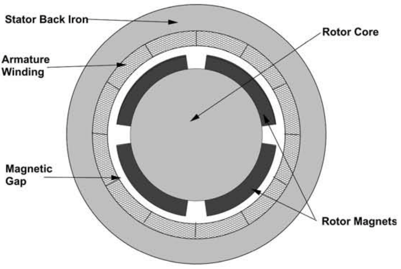 Figure 4: Axial View of a PM Motor With an Air-Gap Winding