1.2: Sinusoidal Waveforms
- Page ID
- 25161
AC, or alternating current, is so named because the current alternates or flips back and forth between two polarities. In other words, the current (and consequently the voltage) is a function of time. This is fundamentally different from direct current that is fixed in polarity and generally constant over time. A laboratory DC voltage source, for example, ideally maintains a set voltage across its terminals and does not vary over time. In contrast, as an AC waveform swings back and forth through time, its shape can exhibit wide variations ranging from the simple, regular paths of laboratory standards such as sine waves, triangle waves and square waves, to the far more complex and undulating waveforms produced by musical instruments and the human voice.
The sine wave is the simplest wave that may be created. It represents the motion of a simple vector rotating at a constant speed, such as the vertical displacement of the second hand of a clock. An example is shown in Figure \(\PageIndex{1}\). The horizontal axis plots time. It increases as we move from left to right (i.e., if point A is to the right of point B, then A occurs later in time than does B). The vertical axis is represented here in general as a percentage of maximum but would ordinarily be a measurement of voltage, current, sound pressure, or the like.
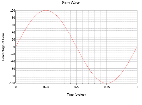
Note the smooth variation that starts at zero, rises to a positive peak one quarter way through, falls back to zero when halfway through, continues to a negative peak three quarters through, and then rises again to where it started. This process then repeats. Each repeat is referred to as a cycle. In Figure \(\PageIndex{1}\), one complete cycle is shown.
Sine waves exhibit quarter wave symmetry. That is, each quarter (in time) of the wave is identical to any other if you simply flip it around the horizontal axis and/or rotate it upright about its peak. The time it takes to complete one cycle is called the period and is denoted with the symbol \(T\) (for Time). The reciprocal of the period is the frequency, \(f\).
\[f = \frac{1}{T} \label{1.1} \]
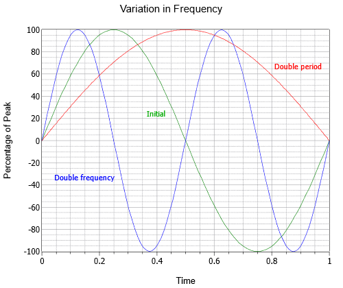
The frequency indicates how many cycles exist in one second. To honor one of the 19th century researchers in the field, instead of calling the unit “cycles per second”, we use Hertz, named after Heinrich Hertz and abbreviated Hz. In Figure \(\PageIndex{2}\) three sine waves are shown with different frequencies; the initial wave (green), a wave at twice the frequency (blue), and a third at half the frequency or twice the period (red).
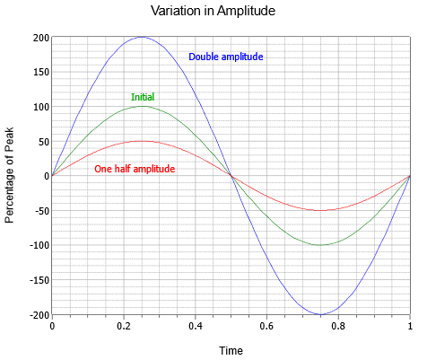
The amplitude (vertical) of the wave can be expressed as a peak quantity, which is the change from the center zero line up to the most positive value. Amplitude may also be expressed as peak-to-peak; the distance from the most negative to the most positive. For a sine wave this will always be twice the peak value, although that might not be the case for other waves which may be asymmetrical. A series of three sine waves with differing amplitudes are shown in Figure \(\PageIndex{3}\). Along side the initial (green) are double amplitude (blue) and half amplitude (red) versions.
Combining these parameters, consider the voltage waveform shown in Figure \(\PageIndex{4}\). Here we see two cycles of an AC voltage waveform.
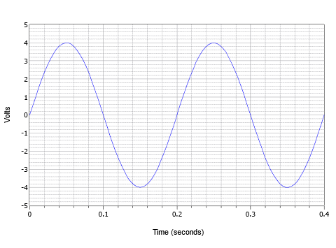
The peak value is 4 volts and the peak-to-peak value is 8 volts (typically abbreviated as “8 V pp”). The period of one cycle is 0.2 seconds, or \(T = 200\) milliseconds. Further, the frequency, \(f = 1/200\) milliseconds, or 5 Hz (5 cycles in one second).
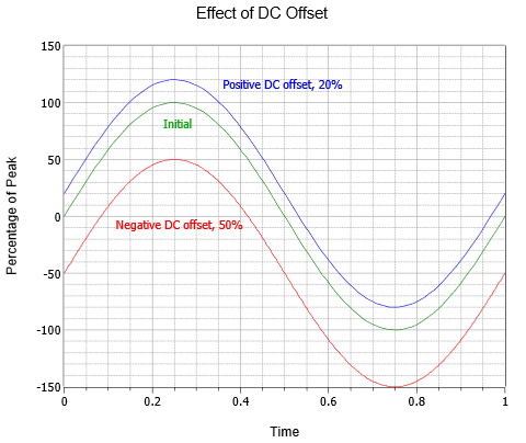
AC waveforms may also be combined with a DC offset. Adding a positive DC level shifts the wave up vertically, while a negative DC level shifts the wave down vertically. This does not alter the frequency or AC portion of the amplitude (although the absolute peaks would shift by the DC value). Figure \(\PageIndex{5}\) shows the effect of various DC offsets. Above the initial wave (green) is an otherwise identical wave with a positive DC offset equal to 20% of the original peak value (blue). Below the original is a third wave (red) that exhibits a negative DC offset equal to half of the peak value of the original.
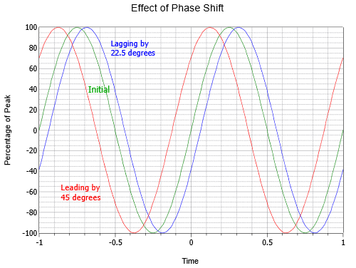
Further, it is possible for a sine wave to be shifted in time compared to some other sine wave or reference. While it is possible to indicate this shift as an absolute time, it is more common to do so as a phase shift, that is, the time expressed as a portion of the period in degrees. For example, if one sine is ahead of another by one quarter of the period, it is said to be leading by 90\(^{\circ}\) (i.e., 1/4 of 360\(^{\circ}\)). If it is behind by ½ of the period, it is said to be lagging by 180\(^{\circ}\) (i.e., later in time by 1/2 cycle). Another way of stating this is that leading waveforms start earlier in time and thus are drawn to the left of the reference, while lagging waveforms start later in time and are drawn to the right.
Figure \(\PageIndex{6}\) illustrates the effect of phase shift. Note that in this plot, \(t = 0\) has been moved to the center of the horizontal axis. The middle curve is the initial, or reference, wave (green). To the left (red) is a wave leading the initial wave by one-eighth cycle, or 45\(^{\circ}\). To the right (blue), is a lagging wave of half as much, or −22.5\(^{\circ}\).
Combining the foregoing elements allows us to develop a general format for a sine wave (voltage shown):
\[v(t) = V_{DC} + V_{P} \sin (2 \pi f t + \theta) \label{1.2} \]
where
- \(v(t)\) is the voltage at some time \(t\),
- \(V_{DC}\) is the DC offset, if any,
- \(V_{P}\) is the peak value,
- \(f\) is the frequency,
- \(\theta\) is the phase shift (+ if leading and drawn to the left, − if lagging and drawn to the right).
For a quick and practical example, the waveform shown in Figure \(\PageIndex{4}\) has an amplitude of 4 volts peak, a frequency of 5 Hz, and no DC offset or phase shift. Thus, its expression is \(v(t) = 4 \sin (2 \pi 5 t)\)
To compute a phase shift, first determine the time differential between the waveform and the reference, which we'll call \(\Delta t\). The reference may be a fixed point in time (e.g., \(t = 0\)) or another waveform. Generally, the easy way to do this is to measure the difference at the zero-crossings, assuming there is no DC offset. If there is an offset, make the measurement where the zero crossing has been shifted to (i.e., at the DC offset level). Once the difference is found, divide it by the period to represent the shift as a fraction of a period. As one cycle represents one rotation of the vector, or 360 degrees, simply multiply the fraction by 360 degrees to find the phase shift in degrees. Expressed as a formula:
\[\theta = 360^{\circ} \frac{\Delta t}{T} \label{1.3} \]
Remember, if the wave is shifted to the left then it is leading and positive, while a shift to the right is lagging or delayed in time, and thus negative.
Example \(\PageIndex{1}\)
Write the expression for the waveform shown in Figure \(\PageIndex{7}\).
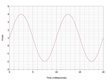
This waveform superficially may look like the one in Figure \(\PageIndex{4}\) but don't let this fool you. First of all, the time scale is different. For this waveform, one cycle completes in 10 milliseconds. Therefore, the frequency is
\[\begin{align} f &= \frac{1}{T} \\[4pt] &= \frac{1}{10 ms} \\[4pt] &= 100 Hz \end{align} \nonumber \]
The second issue is the DC offset. Note that the positive peak occurs at 4 amps while the negative peak occurs at −2 amps. This indicates a peak-topeak value of 6 amps. Without an offset, the positive peak would be at 3 amps, therefore there is a +1 amp DC offset. The vertical center of the waveform is shifted up from 0 amps to +1 amp. This point is at t = 0, therefore, there is no phase shift. The resulting expression is:
\[i(t) = 1 + 3 \sin (2 \pi 100 t) \nonumber \]
Example \(\PageIndex{2}\)
Write the expression for the waveform shown in Figure \(\PageIndex{8}\).
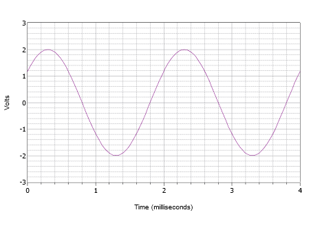
First off, the positive peak is 2 volts and the peak-to-peak value is 4 volts. Therefore there is no DC offset. The vertical center of the wave does not start at \(t = 0\), thus there must be a phase shift. The value at \(t = 0\) is 1.2 volts. The wave hits this same amplitude at \(t = 2\) milliseconds and begins to repeat another cycle. Consequently the period must be 2 milliseconds. The frequency is the reciprocal of this value, and thus \(f = 500\) Hz.
The waveform is shifted to the left which indicates a positive or leading phase shift. If we examine the second cycle, we see that it hits zero volts at 1.8 milliseconds. Therefore the shift is 0.2 milliseconds. Expressed in degrees this is:
\[\theta = 360^{\circ} \frac{\Delta t}{T} \nonumber \]
\[\theta = 360^{\circ} \frac{0.2ms}{2 ms} \nonumber \]
\[\theta = 36^{\circ} \nonumber \]
The final expression is:
\[v(t) = 2 \sin (2 \pi 500 t + 36^{\circ}) \nonumber \]
Example \(\PageIndex{3}\)
Draw the waveform corresponding to the following expression.
\[v(t) = −3 + 5 \sin (2 \pi 40000 t − 72^{\circ}) \nonumber \]
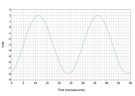
First, note that the −3 volt offset pushes the positive peak down from 5 volts to 2 volts, and the negative peak down from −5 volts to −8 volts. The frequency of 40 kHz dictates a period of:
\[\begin{align*} T &= \frac{1}{f} \\[4pt] &= \frac{1}{40 kHz} \\[4pt] &= 25 \mu s \end{align*} \nonumber \]
The phase shift of −72\(^{\circ}\) represents 72/360, or 0.2 cycles. This corresponds to a time delay (shifted right because it's negative) of 0.2 times 25 \(\mu\)s, or 5 \(\mu\)s.
Initially, it is often best to construct the plot via a series of discrete steps rather than trying to draw the entire thing in one go. First, draw a sine wave with a 5 volt peak amplitude and a period of 25 \(\mu\)s. Now, push the waveform down 3 volts so that the positive peak is only 2 volts and the negative peak is down at −8 volts. Finally, push the newly shifted waveform to the right by 5 \(\mu\)s. The result is shown in Figure \(\PageIndex{9}\).
Laboratory Measurements
In the laboratory, a function generator is used to generate sines and other waveshapes. These devices will allow precise control over both the amplitude and frequency of the wave along with adding a DC offset, if desired. An example is shown in Figure \(\PageIndex{10}\). The corresponding measurement tool is the oscilloscope, or just scope, for short.

The oscilloscope is perhaps the most useful and versatile measurement device in the laboratory. Typically, they feature either two or four input channels, although more are possible. Each input channel has its own sensitivity adjustment and all channels share a common time reference. The display draws waveforms in the same manner as those seen in Figures \(\PageIndex{1}\) – \(\PageIndex{9}\). Also, they can plot one voltage versus another (X – Y mode). Modern oscilloscopes have additional features such as the automatic measurement of frequency, amplitude, phase shift, etc., cursor-based measurements, and the ability to save display images as graphics files. An example of a four channel digital oscilloscope is shown in Figure \(\PageIndex{11}\).

Schematic Symbols
As far as schematics are concerned, the symbols for AC voltage and current sources are shown in Figure \(\PageIndex{12}\). The polarity and direction markings are not absolute; after all, these are AC sources whose polarity and directions flip back and forth. The markers are instead used to establish a timing reference, especially in circuits employing multiple sources.

It is worth remembering that negating a source is the same as flipping its polarity. This was true for DC sources and remains true for AC sources. This is illustrated in Figure \(\PageIndex{13}\). Sometimes flipping or negating source will make analysis a little more obvious or easier to visualize.

Example \(\PageIndex{4}\)
Assume an oscilloscope displays two waves as depicted in Figure \(\PageIndex{14}\). Determine the phase shift of the smaller 20 volt peak (blue) waveform relative to the larger 25 volt peak (red) waveform.
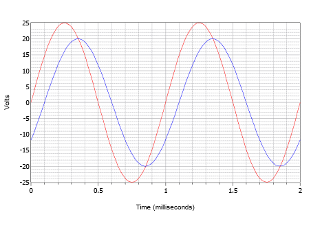
First, note that neither wave exhibits a DC offset. If one or both them had an offset, the wave(s) would have to be shifted vertically so that their normal zero-crossing points would be at the same level. Measuring either wave, the period is found to be 1 millisecond. The time shift most easily can be found at any of the zero-crossings (there are four locations to choose from). The delay is one small deviation, or 0.1 milliseconds, with the smaller wave delayed in time, or lagging the larger wave. This indicates a negative phase shift.
\[\theta = 360^{\circ} \frac{\Delta t}{T} \nonumber \]
\[\theta = 360^{\circ} \frac{−0.1 ms}{1 ms} \nonumber \]
\[\theta = −36^{\circ} \nonumber \]
Sines and Cosines
There are a handful of specific phase shifts that are worth a closer look. If a sine wave is inverted, that is, flipped upside down, it is indistinguishable from a sine wave that has been shifted either +180 or −180 degrees. In other words, such a wave can be written three different ways: \(− \sin (2 \pi ft)\), \(\sin (2 \pi ft − 180^{\circ})\), or \(\sin (2 \pi ft + 180^{\circ})\). Further, if a sine wave is shifted by +90 degrees (i.e., leading and to the left), it may also be referred to as a cosine wave. Thus \(\sin (2 \pi ft + 90^{\circ}) = \ cos (2 \pi ft)\). Finally, if a sine wave is shifted by −90 degrees (i.e., lagging and to the right), it may be referred to as a negative or inverted cosine wave. Thus \(\sin (2 \pi ft − 90^{\circ}) = − \cos (2 \pi ft)\). The relationships of these four waves are illustrated in Figure \(\PageIndex{15}\).
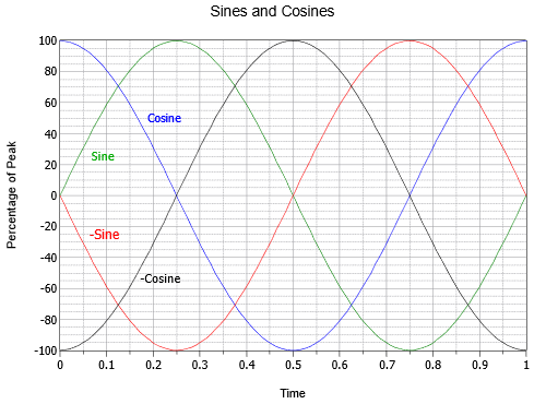
It is also worth noting that the cosine wave represents the first derivative, or slope, of the sine wave. As you may recall from other studies, the slope or “steepness” of a line is the ratio of the vertical change to the horizontal change, sometimes called “the rise over the run”. For a voltage, it would be the change in voltage over the change in time, or \(\Delta V/ \Delta t\). For a smooth, continuously changing curve like a sine wave, the slope at a given point is defined properly as the first derivative, or \(dv/dt\) in this case. To verify that this is true visually, note that the steepest part of the sine wave (green) is where it crosses zero amplitude. As it crosses zero while moving positive (at \(t = 0\) or \(t = 1\) in Figure \(\PageIndex{15}\)), the cosine (blue) is at its positive peak. As the sine cross zero while moving negative (at \(t = 0.5\)), the cosine is at its negative peak. Further, the sine wave is flat with a slope of zero at its positive and negative peaks (at at \(t = 0.25\) and \(t = 0.75\), respectively), and at those times the cosine's amplitude is also zero. It is also true that the sine wave is the slope of the negative cosine wave, the negative cosine is the slope of the negative sine, and the negative sine is the slope of the cosine. Moving in the reverse direction, we can say that the anti-derivative (indefinite integral) of a cosine wave is a sine wave, the integral of a sine wave is a negative cosine wave, and so forth. These relationships will prove most useful when we turn our attention to the response of capacitors and inductors in AC circuits.
– Root Mean Square Measurement
Along with peak and peak-to-peak, amplitude may be given as an RMS (Root Mean Square) value. In fact, if peak or peak-to-peak is not specified, the measurement is assumed to be RMS. RMS is a special calculation used for finding equivalent DC power (very common, for example, with audio power amplifiers). In other words, if we are interested in finding the power in a resistor, the calculation must be performed using RMS values for voltage or current, not peak or peak-to-peak values. Failure to do so will result in erroneous powers. This is true regardless of the waveshape; be it a sine wave, triangle wave or the complex waves of music signals. If a voltage is specified as RMS, it can be treated for power calculations just like an equivalently sized DC voltage. For example, a 1 volt RMS sine will produce the same power dissipation and heating in a given resistor as will 1 volt DC. For this reason, RMS is sometimes referred to as the effective value (i.e., effective DC value).
The name root-mean-square describes the process of determining the effective value. First, recall that power is proportional to the square of the voltage or current. Thus, our first step will be to square the input waveform. Of course, the waveform is a function of time and its square will yield some new shape. At this point, we need to find the average value of this new shape. The reason for this is simple, yet not necessarily obvious. Electrical and electronic components have mass, and thus do not heat or cool instantly. They exhibit a thermal time constant. Therefore, they respond to the average input over time. While we could compute some manner of “instantaneous peak power” at some specific instant in time, it does not represent the equivalent DC power. Once we have obtained the mean value of this squared waveform, the corresponding DC value is just the square root of the mean. The result is a fractional value between zero and one that is used as a scaling factor to turn a peak value into an RMS value. The value will be unique to the specific waveshape. That is, all sines (regardless of phase) have the same factor, all regular triangle waves have the same factor, and so on. As we mostly concern ourselves with sines, let's take a closer look at determining the RMS factor for them.
We begin with the basic expression for a sine wave without DC offset or phase shift, and with an amplitude of one:
\[v(t) = \sin (2 \pi f t) \nonumber \]
The first step is to square this waveform. A useful trigonometric identity is
\[( \sin x)^2 = \frac{1}{2} − \frac{1}{2} \cos 2 x \nonumber \]
Applying this to our wave yields:
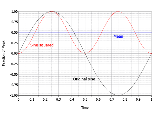
\[v(t)^2 = \frac{1}{2} − \frac{1}{2} \cos (2 \pi 2 f t) \nonumber \]
This expression describes an inverted cosine wave at twice the original frequency and half of the original amplitude, riding on a DC offset equal to its peak value. In other words, the negative peak of the cosine is at zero and the positive peak is at 1. The next step is to find the average or mean value of this intermediate result. The mean is equal to the offset of 0.5. This can be visualized as the area above the offset perfectly filling the “dip” below the offset. The final step is to take the square root of the mean. The square root of 0.5 is equal to one over the square root of two, or approximately 0.707. Therefore the RMS value is 0.707 times the peak. Alternately, you could divide the peak by square root of two, or approximately 1.414. This process is shown graphically in Figure \(\PageIndex{16}\).
In summation, for sine waves, RMS is always the peak value times 0.707. We could also say the RMS value of any sine wave is its peak divided by approximately 1.414. Again, these ratios would not necessarily be true of non-sine waves. Details regarding other common shapes can be found in Appendix C. Finally, the ratio of the peak value to the RMS value is called the crest ratio. This is a fixed value for sine waves (again, about 1.414), but can be over 10:1 for some kinds of audio signals.
Wavelength
Another item of interest is the speed of propagation of the wave. This varies widely. In the case of light in a vacuum (or to a close approximation, an electrical current in a wire), the velocity is about 3E8 meters per second (i.e., 300,000 km/s) or about 186,000 miles per second.
Given a velocity and a period, we can imagine how far apart the peaks of the wave are. This distance is called the wavelength and is denoted by the Greek letter lambda \(\lambda\). Wavelength is equal to the velocity divided by the frequency, \(\lambda = v/f\). Thus, for a loudspeaker producing a 100 Hz sine, as the velocity of sound in air is 344 m/s, then \(\lambda = 344 m/s \, / \, 100\) Hz, or 3.44 meters (a little over 11 feet). Notice that the higher the frequency, the shorter the wavelength. Also, note that the faster the velocity, the longer the wavelength. Wavelength calculations are of particular importance in the fields of telecommunications and acoustics.


