
5.10: Baluns
- Page ID
- 41114
\( \newcommand{\vecs}[1]{\overset { \scriptstyle \rightharpoonup} {\mathbf{#1}} } \)
\( \newcommand{\vecd}[1]{\overset{-\!-\!\rightharpoonup}{\vphantom{a}\smash {#1}}} \)
\( \newcommand{\dsum}{\displaystyle\sum\limits} \)
\( \newcommand{\dint}{\displaystyle\int\limits} \)
\( \newcommand{\dlim}{\displaystyle\lim\limits} \)
\( \newcommand{\id}{\mathrm{id}}\) \( \newcommand{\Span}{\mathrm{span}}\)
( \newcommand{\kernel}{\mathrm{null}\,}\) \( \newcommand{\range}{\mathrm{range}\,}\)
\( \newcommand{\RealPart}{\mathrm{Re}}\) \( \newcommand{\ImaginaryPart}{\mathrm{Im}}\)
\( \newcommand{\Argument}{\mathrm{Arg}}\) \( \newcommand{\norm}[1]{\| #1 \|}\)
\( \newcommand{\inner}[2]{\langle #1, #2 \rangle}\)
\( \newcommand{\Span}{\mathrm{span}}\)
\( \newcommand{\id}{\mathrm{id}}\)
\( \newcommand{\Span}{\mathrm{span}}\)
\( \newcommand{\kernel}{\mathrm{null}\,}\)
\( \newcommand{\range}{\mathrm{range}\,}\)
\( \newcommand{\RealPart}{\mathrm{Re}}\)
\( \newcommand{\ImaginaryPart}{\mathrm{Im}}\)
\( \newcommand{\Argument}{\mathrm{Arg}}\)
\( \newcommand{\norm}[1]{\| #1 \|}\)
\( \newcommand{\inner}[2]{\langle #1, #2 \rangle}\)
\( \newcommand{\Span}{\mathrm{span}}\) \( \newcommand{\AA}{\unicode[.8,0]{x212B}}\)
\( \newcommand{\vectorA}[1]{\vec{#1}} % arrow\)
\( \newcommand{\vectorAt}[1]{\vec{\text{#1}}} % arrow\)
\( \newcommand{\vectorB}[1]{\overset { \scriptstyle \rightharpoonup} {\mathbf{#1}} } \)
\( \newcommand{\vectorC}[1]{\textbf{#1}} \)
\( \newcommand{\vectorD}[1]{\overrightarrow{#1}} \)
\( \newcommand{\vectorDt}[1]{\overrightarrow{\text{#1}}} \)
\( \newcommand{\vectE}[1]{\overset{-\!-\!\rightharpoonup}{\vphantom{a}\smash{\mathbf {#1}}}} \)
\( \newcommand{\vecs}[1]{\overset { \scriptstyle \rightharpoonup} {\mathbf{#1}} } \)
\(\newcommand{\longvect}{\overrightarrow}\)
\( \newcommand{\vecd}[1]{\overset{-\!-\!\rightharpoonup}{\vphantom{a}\smash {#1}}} \)
\(\newcommand{\avec}{\mathbf a}\) \(\newcommand{\bvec}{\mathbf b}\) \(\newcommand{\cvec}{\mathbf c}\) \(\newcommand{\dvec}{\mathbf d}\) \(\newcommand{\dtil}{\widetilde{\mathbf d}}\) \(\newcommand{\evec}{\mathbf e}\) \(\newcommand{\fvec}{\mathbf f}\) \(\newcommand{\nvec}{\mathbf n}\) \(\newcommand{\pvec}{\mathbf p}\) \(\newcommand{\qvec}{\mathbf q}\) \(\newcommand{\svec}{\mathbf s}\) \(\newcommand{\tvec}{\mathbf t}\) \(\newcommand{\uvec}{\mathbf u}\) \(\newcommand{\vvec}{\mathbf v}\) \(\newcommand{\wvec}{\mathbf w}\) \(\newcommand{\xvec}{\mathbf x}\) \(\newcommand{\yvec}{\mathbf y}\) \(\newcommand{\zvec}{\mathbf z}\) \(\newcommand{\rvec}{\mathbf r}\) \(\newcommand{\mvec}{\mathbf m}\) \(\newcommand{\zerovec}{\mathbf 0}\) \(\newcommand{\onevec}{\mathbf 1}\) \(\newcommand{\real}{\mathbb R}\) \(\newcommand{\twovec}[2]{\left[\begin{array}{r}#1 \\ #2 \end{array}\right]}\) \(\newcommand{\ctwovec}[2]{\left[\begin{array}{c}#1 \\ #2 \end{array}\right]}\) \(\newcommand{\threevec}[3]{\left[\begin{array}{r}#1 \\ #2 \\ #3 \end{array}\right]}\) \(\newcommand{\cthreevec}[3]{\left[\begin{array}{c}#1 \\ #2 \\ #3 \end{array}\right]}\) \(\newcommand{\fourvec}[4]{\left[\begin{array}{r}#1 \\ #2 \\ #3 \\ #4 \end{array}\right]}\) \(\newcommand{\cfourvec}[4]{\left[\begin{array}{c}#1 \\ #2 \\ #3 \\ #4 \end{array}\right]}\) \(\newcommand{\fivevec}[5]{\left[\begin{array}{r}#1 \\ #2 \\ #3 \\ #4 \\ #5 \\ \end{array}\right]}\) \(\newcommand{\cfivevec}[5]{\left[\begin{array}{c}#1 \\ #2 \\ #3 \\ #4 \\ #5 \\ \end{array}\right]}\) \(\newcommand{\mattwo}[4]{\left[\begin{array}{rr}#1 \amp #2 \\ #3 \amp #4 \\ \end{array}\right]}\) \(\newcommand{\laspan}[1]{\text{Span}\{#1\}}\) \(\newcommand{\bcal}{\cal B}\) \(\newcommand{\ccal}{\cal C}\) \(\newcommand{\scal}{\cal S}\) \(\newcommand{\wcal}{\cal W}\) \(\newcommand{\ecal}{\cal E}\) \(\newcommand{\coords}[2]{\left\{#1\right\}_{#2}}\) \(\newcommand{\gray}[1]{\color{gray}{#1}}\) \(\newcommand{\lgray}[1]{\color{lightgray}{#1}}\) \(\newcommand{\rank}{\operatorname{rank}}\) \(\newcommand{\row}{\text{Row}}\) \(\newcommand{\col}{\text{Col}}\) \(\renewcommand{\row}{\text{Row}}\) \(\newcommand{\nul}{\text{Nul}}\) \(\newcommand{\var}{\text{Var}}\) \(\newcommand{\corr}{\text{corr}}\) \(\newcommand{\len}[1]{\left|#1\right|}\) \(\newcommand{\bbar}{\overline{\bvec}}\) \(\newcommand{\bhat}{\widehat{\bvec}}\) \(\newcommand{\bperp}{\bvec^\perp}\) \(\newcommand{\xhat}{\widehat{\xvec}}\) \(\newcommand{\vhat}{\widehat{\vvec}}\) \(\newcommand{\uhat}{\widehat{\uvec}}\) \(\newcommand{\what}{\widehat{\wvec}}\) \(\newcommand{\Sighat}{\widehat{\Sigma}}\) \(\newcommand{\lt}{<}\) \(\newcommand{\gt}{>}\) \(\newcommand{\amp}{&}\) \(\definecolor{fillinmathshade}{gray}{0.9}\)A balun [16, 17] is a structure that joins balanced and unbalanced circuits. The word itself (balun) is a contraction of balanced-to-unbalanced
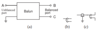
Figure \(\PageIndex{1}\): A balun: (a) as a two-port with four terminals; (b) IEEE standard schematic symbol for a balun [9]; and (c) an (unbalanced) coaxial cable driving a dipole antenna through a balun.
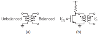
Figure \(\PageIndex{2}\): : Balun: (a) schematic representation as a transformer showing unbalanced and balanced ports; and (b) connected to a single-ended unbalanced amplifier yielding a balanced output.
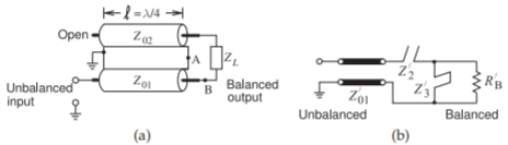
Figure \(\PageIndex{3}\): Marchand balun: (a) coaxial form of the Marchand balun; and (b) its equivalent circuit.
transformer. Representations of a balun are shown in Figure \(\PageIndex{1}\). A situation when a balun is required is with an antenna. Many antennas do not operate correctly if part of the antenna is at the same potential electrically as the ground. Instead, the antenna should be electrically isolated from the ground (i.e., balanced). The antenna would usually be fed by a coaxial cable with its outer conductor connected to ground, and so a balun is required between the cable and the antenna.
A balun is a key component of many RF and microwave communications systems [18, 19]. Baluns are used in balanced circuits, such as antennas, double-balanced mixers, push-pull amplifiers, and frequency doublers [20]. Another application of a balun is in a system using RFICs, where a balun transforms the differential outputs of an RFIC to unbalanced microwave circuitry. The schematic of a magnetic transformer used as a balun is shown in Figure \(\PageIndex{2}\)(a) with one terminal of the unbalanced port grounded. Figure \(\PageIndex{1}\)(b) is the standard schematic symbol for a balun and its use with a dipole antenna is shown in Figure \(\PageIndex{1}\)(c). The second port is floating and is not referenced to ground. An example of the use of a balun is shown in Figure \(\PageIndex{2}\)(b), where the amplifier is called a single-ended amplifier and its output is unbalanced, being referred to ground. A balun transitions from the unbalanced transistor output to a balanced output.
5.10.1 Marchand Balun
The most common form of microwave balun is the Marchand balun [16, 20, 21, 22, 23]. An implementation of the Marchand balun using coaxial transmission lines is shown in Figure \(\PageIndex{3}\)(a) [24]. It can also be realized in planar form [16]. The \(Z_{02}\) line acts as both a series stub and a shunt stub. Thus the model of the Marchand balun is as shown in Figure \(\PageIndex{3}\)(b).
The drawback of the conventional Marchand balun is that the center frequency of the balun is actually the resonant frequency of the transmission
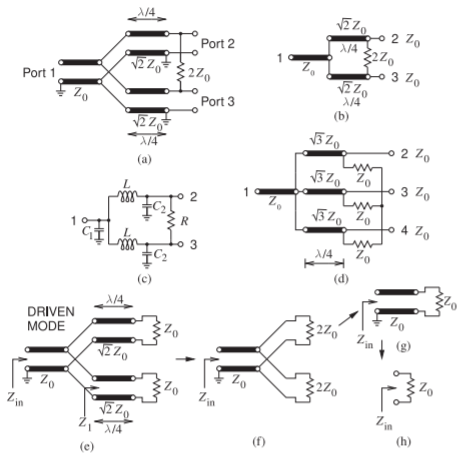
Figure \(\PageIndex{4}\): Wilkinson divider: (a) two-way divider with Port \(\mathsf{1}\) being the combined signal and Ports \(\mathsf{2}\) and \(\mathsf{3}\) being the divided signals; (b) less cluttered representation; (c) lumped-element implementation; (d) three-way divider with Port \(\mathsf{1}\) being the combined signal and Ports \(\mathsf{2,}\: \mathsf{3,}\) and \(\mathsf{4}\) being the divided signals; and (e)–(h) steps in the derivation of the input impedance.
line resonators forming the balun. Thus the overall size of a conventional Marchand balun can be large, with the size determined by the transmission line sections, which are one-quarter wavelength long at the balun center frequency. Network synthesis can lead to miniaturized baluns by shifting the one-quarter wavelength frequency up while maintaining the balun center frequency [23].