
5.5: Ferrite Components- Circulators and Isolators
- Page ID
- 46130

\( \newcommand{\vecs}[1]{\overset { \scriptstyle \rightharpoonup} {\mathbf{#1}} } \)
\( \newcommand{\vecd}[1]{\overset{-\!-\!\rightharpoonup}{\vphantom{a}\smash {#1}}} \)
\( \newcommand{\dsum}{\displaystyle\sum\limits} \)
\( \newcommand{\dint}{\displaystyle\int\limits} \)
\( \newcommand{\dlim}{\displaystyle\lim\limits} \)
\( \newcommand{\id}{\mathrm{id}}\) \( \newcommand{\Span}{\mathrm{span}}\)
( \newcommand{\kernel}{\mathrm{null}\,}\) \( \newcommand{\range}{\mathrm{range}\,}\)
\( \newcommand{\RealPart}{\mathrm{Re}}\) \( \newcommand{\ImaginaryPart}{\mathrm{Im}}\)
\( \newcommand{\Argument}{\mathrm{Arg}}\) \( \newcommand{\norm}[1]{\| #1 \|}\)
\( \newcommand{\inner}[2]{\langle #1, #2 \rangle}\)
\( \newcommand{\Span}{\mathrm{span}}\)
\( \newcommand{\id}{\mathrm{id}}\)
\( \newcommand{\Span}{\mathrm{span}}\)
\( \newcommand{\kernel}{\mathrm{null}\,}\)
\( \newcommand{\range}{\mathrm{range}\,}\)
\( \newcommand{\RealPart}{\mathrm{Re}}\)
\( \newcommand{\ImaginaryPart}{\mathrm{Im}}\)
\( \newcommand{\Argument}{\mathrm{Arg}}\)
\( \newcommand{\norm}[1]{\| #1 \|}\)
\( \newcommand{\inner}[2]{\langle #1, #2 \rangle}\)
\( \newcommand{\Span}{\mathrm{span}}\) \( \newcommand{\AA}{\unicode[.8,0]{x212B}}\)
\( \newcommand{\vectorA}[1]{\vec{#1}} % arrow\)
\( \newcommand{\vectorAt}[1]{\vec{\text{#1}}} % arrow\)
\( \newcommand{\vectorB}[1]{\overset { \scriptstyle \rightharpoonup} {\mathbf{#1}} } \)
\( \newcommand{\vectorC}[1]{\textbf{#1}} \)
\( \newcommand{\vectorD}[1]{\overrightarrow{#1}} \)
\( \newcommand{\vectorDt}[1]{\overrightarrow{\text{#1}}} \)
\( \newcommand{\vectE}[1]{\overset{-\!-\!\rightharpoonup}{\vphantom{a}\smash{\mathbf {#1}}}} \)
\( \newcommand{\vecs}[1]{\overset { \scriptstyle \rightharpoonup} {\mathbf{#1}} } \)
\(\newcommand{\longvect}{\overrightarrow}\)
\( \newcommand{\vecd}[1]{\overset{-\!-\!\rightharpoonup}{\vphantom{a}\smash {#1}}} \)
\(\newcommand{\avec}{\mathbf a}\) \(\newcommand{\bvec}{\mathbf b}\) \(\newcommand{\cvec}{\mathbf c}\) \(\newcommand{\dvec}{\mathbf d}\) \(\newcommand{\dtil}{\widetilde{\mathbf d}}\) \(\newcommand{\evec}{\mathbf e}\) \(\newcommand{\fvec}{\mathbf f}\) \(\newcommand{\nvec}{\mathbf n}\) \(\newcommand{\pvec}{\mathbf p}\) \(\newcommand{\qvec}{\mathbf q}\) \(\newcommand{\svec}{\mathbf s}\) \(\newcommand{\tvec}{\mathbf t}\) \(\newcommand{\uvec}{\mathbf u}\) \(\newcommand{\vvec}{\mathbf v}\) \(\newcommand{\wvec}{\mathbf w}\) \(\newcommand{\xvec}{\mathbf x}\) \(\newcommand{\yvec}{\mathbf y}\) \(\newcommand{\zvec}{\mathbf z}\) \(\newcommand{\rvec}{\mathbf r}\) \(\newcommand{\mvec}{\mathbf m}\) \(\newcommand{\zerovec}{\mathbf 0}\) \(\newcommand{\onevec}{\mathbf 1}\) \(\newcommand{\real}{\mathbb R}\) \(\newcommand{\twovec}[2]{\left[\begin{array}{r}#1 \\ #2 \end{array}\right]}\) \(\newcommand{\ctwovec}[2]{\left[\begin{array}{c}#1 \\ #2 \end{array}\right]}\) \(\newcommand{\threevec}[3]{\left[\begin{array}{r}#1 \\ #2 \\ #3 \end{array}\right]}\) \(\newcommand{\cthreevec}[3]{\left[\begin{array}{c}#1 \\ #2 \\ #3 \end{array}\right]}\) \(\newcommand{\fourvec}[4]{\left[\begin{array}{r}#1 \\ #2 \\ #3 \\ #4 \end{array}\right]}\) \(\newcommand{\cfourvec}[4]{\left[\begin{array}{c}#1 \\ #2 \\ #3 \\ #4 \end{array}\right]}\) \(\newcommand{\fivevec}[5]{\left[\begin{array}{r}#1 \\ #2 \\ #3 \\ #4 \\ #5 \\ \end{array}\right]}\) \(\newcommand{\cfivevec}[5]{\left[\begin{array}{c}#1 \\ #2 \\ #3 \\ #4 \\ #5 \\ \end{array}\right]}\) \(\newcommand{\mattwo}[4]{\left[\begin{array}{rr}#1 \amp #2 \\ #3 \amp #4 \\ \end{array}\right]}\) \(\newcommand{\laspan}[1]{\text{Span}\{#1\}}\) \(\newcommand{\bcal}{\cal B}\) \(\newcommand{\ccal}{\cal C}\) \(\newcommand{\scal}{\cal S}\) \(\newcommand{\wcal}{\cal W}\) \(\newcommand{\ecal}{\cal E}\) \(\newcommand{\coords}[2]{\left\{#1\right\}_{#2}}\) \(\newcommand{\gray}[1]{\color{gray}{#1}}\) \(\newcommand{\lgray}[1]{\color{lightgray}{#1}}\) \(\newcommand{\rank}{\operatorname{rank}}\) \(\newcommand{\row}{\text{Row}}\) \(\newcommand{\col}{\text{Col}}\) \(\renewcommand{\row}{\text{Row}}\) \(\newcommand{\nul}{\text{Nul}}\) \(\newcommand{\var}{\text{Var}}\) \(\newcommand{\corr}{\text{corr}}\) \(\newcommand{\len}[1]{\left|#1\right|}\) \(\newcommand{\bbar}{\overline{\bvec}}\) \(\newcommand{\bhat}{\widehat{\bvec}}\) \(\newcommand{\bperp}{\bvec^\perp}\) \(\newcommand{\xhat}{\widehat{\xvec}}\) \(\newcommand{\vhat}{\widehat{\vvec}}\) \(\newcommand{\uhat}{\widehat{\uvec}}\) \(\newcommand{\what}{\widehat{\wvec}}\) \(\newcommand{\Sighat}{\widehat{\Sigma}}\) \(\newcommand{\lt}{<}\) \(\newcommand{\gt}{>}\) \(\newcommand{\amp}{&}\) \(\definecolor{fillinmathshade}{gray}{0.9}\)Circulators and isolators are nonreciprocal devices that preferentially route RF signals [14, 15, 16]. The essential element of a circulator is a slab or disc of ferrite which, when magnetized, becomes nonreciprocal, with a preferred direction of propagation resulting from what is called the gyromagnetic effect.
Gyromagnetic Effect
An electron has an intrinsic magnetic field described by its magnetic moment \(m\) (see Figure \(\PageIndex{1}\)(a)) [17]. This is due to a quantum mechanical property called spin bu the electron does not actually spin. In most materials electron spin occurs in pairs with the magnetic field produced by one electron’s spin being canceled by the spin of the other electron. However, in some materials the spin does not occur in pairs and there are regions in which the small magnetic fields produced at the atomic level line up to produce organized regions of directed magnetic field. These regions are called domains, or sometimes magnetic domains, and the combined magnetic field from the aligned electron spins is called a magnetic moment.
The most common magnetic material is ferrite, which is a ceramic containing iron(III) oxide (\(\text{Fe}_{2}\text{O}_{3}\)). Very strong magnetic effects are obtained with materials containing rare earth elements. The rare earth elements, the lanthanoid elements, can align the spins of many electrons of each atom and can produce particularly strong magnetic domains and magnetic moments. The most common rare earth elements used in magnetic materials are samarium and neodymium used in samarium-cobalt and neodymiumiron-boron magnets, respectively.
The domains can be aligned by a strong externally generated magnetic
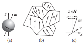
Figure \(\PageIndex{1}\): Magnetic moments: (a) electron withe magnetic moment \(m\); (b), magnetic domains; and (c) progression with a magnetic field bias.
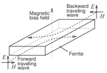
Figure \(\PageIndex{2}\): Gyromagnetic effect on the propagation of EM waves in a magnetic material (here a ferrite) with an externally applied magnetic bias field.
field (e.g., using an electromagnet), and once the domains are aligned they can stay that way for years even when the external field is removed. This situation is shown in Figure \(\PageIndex{1}\)(b), where the individual domains have been almost completely aligned. Each crystal of the material will usually have many magnetic domains and a domain can grow in size (while another reduces or disappears), but generally a domain will not cross a crystal boundary. The domains can also be partially rotated by a moderate applied magnetic field and when the applied field is removed the domains return to their original alignment. The result is that magnetic energy is stored in much the same way as energy is stored in a spring. The amount of energy that is stored depends on the orientation of the applied magnetic field to the domains. The energy storage capability is described by the permeability of the material. In the absence of a constant biasing magnetic field, the permeability would have three values, one for each of the \(x\), \(y\), and \(z\) directions.
A most interesting microwave property occurs when the magnetic material is biased by a strong DC magnetic field. This situation is depicted in Figure \(\PageIndex{1}\)(c). When a time-varying magnetic field is alsoapplied (e.g., the magnetic component of an EM field), the magnetic moment vector will tend to rotate around the DC magnetic field as shown. This is called the gyromagnetic effect. When the frequency of the applied field corresponds to the characteristic frequency of rotation of the magnetic moment then the effect is called gyromagnetic resonance and there is sustained low loss rotation.
Even without resonance (because the magnetic bias field is too small) the gyromagnetic effect affects the way an RF field propagates and this is described by a nine element permeability called a tensor (or a dyadic or a dyadic tensor) that relates each of the three \(H\) field components (in the \(x-\), \(y-\), and \(z-\)directions) to each of the three \(B\) field components. The permeability of a magnetically biased magnetic material is:
\[\label{eq:1}\left[\mu\right] =\left[\begin{array}{ccc}{\mu_{xx}}&{\mu_{xy}}&{\mu_{xz}} \\ {\mu_{yx}}&{\mu_{yy}}&{\mu_{yz}} \\ {\mu_{zx}}&{\mu_{zy}}&{\mu_{zz}}\end{array}\right] =\left[\begin{array}{ccc}{\mu_{0}}&{0}&{0} \\ {0}&{\mu}&{\jmath\kappa} \\ {0}&{-\jmath\kappa}&{\mu}\end{array}\right] \]
This tensor can take other forms depending on the orientation of the time-varying magnetic field to the DC biasing magnetic field.
The effect on propagation of an EM field is shown in Figure \(\PageIndex{2}\). When the EM field is in the magnetized magnetic material, the wave does not travel in a straight line and instead curves, in this case, to the right. Thus forward-and backward-traveling waves diverge from each other and propagation is not reciprocal. This can be used to separate forward- and backward-traveling waves. This is called field displacement.
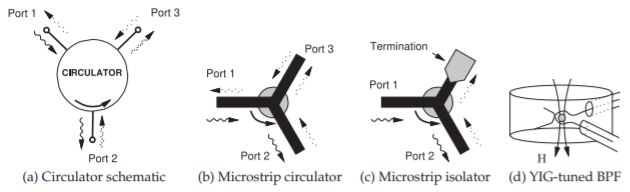
Figure \(\PageIndex{3}\): Ferrite components [21].
Circulator
A circulator exploits the gyromagnetic effect through field displacement [18, 19, 20]. The schematic of a circulator is shown in Figure \(\PageIndex{3}\)(a), where the arrows indicate that the signal that enters Port \(\mathsf{1}\) of the circulator leaves the circulator at Port \(\mathsf{2}\) and not at Port \(\mathsf{3}\). Similarly power that enters at Port \(\mathsf{2}\) is routed to Port \(\mathsf{3}\), and power entering at Port \(\mathsf{3}\) is routed to Port \(\mathsf{1}\). In terms of \(S\) parameters, an ideal circulator has the scattering matrix
\[\label{eq:2}\mathbf{S}=\left[\begin{array}{ccc}{0}&{0}&{S_{13}}\\{S_{21}}&{0}&{0}\\{0}&{S_{32}}&{0}\end{array}\right] = \left[\begin{array}{ccc}{0}&{0}&{1}\\{1}&{0}&{0}\\{0}&{1}&{0}\end{array}\right] \]
A microstrip circulator is shown in Figure \(\PageIndex{3}\)(b), where a disc of magnetized ferrite can be placed on top of a microstrip \(\mathsf{Y}\) junction to realize a preferential direction of propagation of the EM fields [22]. Design requires choice of the size of the ferrite disc and design of the appropriate magnetic biasing field. In the absence of the biasing magnetic field, the circulation function does not occur.
In addition to the insertion and return losses, the performance of a circulator is described by its isolation, which is its insertion loss in the undesired direction.
Circular Isolation
The isolation of a circulator is the insertion loss from what is the output port to the input port, i.e. in the reverse direction. Referring to the circulator in Figure \(\PageIndex{3}\)(a), if port \(\mathsf{1}\) is the input port there are two output ports and so there are two isolations equal to the return loss from port \(\mathsf{3}\) to port \(\mathsf{2}\), and from port \(\mathsf{2}\) to port \(\mathsf{1}\). The smaller of these is the isolation quoted if only one value is given. If this was an ideal circulator and port \(\mathsf{2}\) is perfectly matched, then the isolation would be infinite. If port \(\mathsf{2}\) is not perfectly matched then there will be finite isolation from port \(\mathsf{3}\) to port \(\mathsf{1}\). However the most common source of limited isolation is when the circulator is not perfectly matched. Consider that the reflection coefficient looking into each of the circulator’s ports is \(\Gamma\) and if the circulator is well designed \(\Gamma ≪ 1\). Then the \(S\) parameters of the circulator are
\[\label{eq:3}\mathbf{S}=\left[\begin{array}{ccc}{\Gamma}&{\alpha}&{T}\\{T}&{\Gamma}&{\alpha}\\{\alpha}&{T}&{\Gamma}\end{array}\right] \]
where \(T\) is the transmission factor and is close to \(1\) for a good circulator and the leakage, \(\alpha\), is small. If the circulator is lossless then the unitary conditions, from Equations (2.148) and (2.149) of [23], are
\[\begin{align}\label{eq:4}|T|^{2}+|\alpha|+|\Gamma|^{2}&=1 \\ \label{eq:5}\Gamma\alpha^{\ast}+T\Gamma^{\ast}+\alpha T^{\ast}&=0\to\alpha^{\ast}+T(\Gamma^{\ast}/\Gamma)+T^{\ast}(\alpha /\Gamma)=0\end{align} \]
Since \(\alpha\) is small \(\alpha\Gamma\) is negligibly small, so Equation \(\eqref{eq:5}\) indicates that \(|\alpha | = |\Gamma |\). Then from Equation \(\eqref{eq:4}\), \(|T|^{2} = 1 − 2|\Gamma|^{2}\), and the \(S\) parameters of the lossless slightly-mismatched circulator can be written
\[\label{eq:6}\mathbf{S}=\left[\begin{array}{ccc}{\Gamma}&{\Gamma}&{\sqrt{1-2|\Gamma|^{2}}}\\{\sqrt{1-2|\Gamma|^{2}}}&{\Gamma}&{\Gamma}\\{\Gamma}&{\sqrt{1-2|\Gamma|^{2}}}&{\Gamma}\end{array}\right] \]
Thus even with ideal external matching at port \(\mathsf{2}\), the isolation is \(1/\Gamma\). The quality of the match of a microwave component is typically specified by its VSWR at the ports. Thus the VSWR of a circulator indicates the isolation that can be expected. Actual circulators have a small amount of loss so the isolation and VSWR quoted for a circulator will not conform exactly to the lossless situation considered here.
Isolator
Isolators are devices that allow power flow in only one direction. There are two types, one based on field displacement and the other based on gyromagnetic resonance. Ferrite isolators exploiting field displacement are based on a three-port circulator with one of the ports terminated in a matched load. Figure \(\PageIndex{3}\)(c) shows a microstrip isolator based on a threeport circulator. The puck at the center is a magnetic material such as ferrite that when magnetized by a permanent magnet or electromagnet (which is not shown) preferentially supports a counter-clockwise rotating EM wave. So power entering Port \(\mathsf{1}\) as a traveling wave is transferred to the ferrite and emerges at Port \(\mathsf{2}\). Virtually none of the power emerges at Port \(\mathsf{3}\). A traveling wave signal applied at Port \(\mathsf{2}\) appears at Port \(\mathsf{3}\), where it is absorbed in a termination created by resistive material placed on top of the microstrip. The resistive material forms a lossy transmission line and, provided that the lossy line section is long enough, no power is reflected. Thus power can travel from Port \(\mathsf{1}\) to Port \(\mathsf{2}\), but not in the reverse direction. An isolator is commonly used to protect the output of equipment from high reflected signals. A four-port version can implement a duplexer in radar systems and to separate the received and transmitted signals in a transceiver.
A high-frequency microstrip isolator derived from a circulator is shown in Figure \(\PageIndex{4}\). The input and output lines are at the top and are redirected under the puck. The puck is epoxied to the microstrip substrate and a large biasing magnet is attached on top of the puck. The third port is at the bottom of the figure.
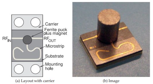
Figure \(\PageIndex{4}\): A microstrip isolator operating from \(29\) to \(31.5\text{ GHz}\). Isolator in (b) has the dimensions \(5\text{ mm}\times 6\text{ mm}\) and is \(6\text{ mm}\) high. The isolator supports \(2\text{ W}\) of forward and reverse power with an isolation of \(18\text{ dB}\) and insertion loss of \(1\text{ dB}\). Renaissance 2W9 series, copyright Renaissance Electronics Corporation, used with permission.
Isolators can also exploit gyromagnetic resonance and are then called resonance isolators. A suitable rotation of the RF magnetic field relative to the DC magnetic bias results for one of the directions of propagation in a rectangular waveguide. At the gyromagnetic resonance frequency, RF energy is coupled into the lattice and RF power is absorbed for one direction of propagation and in the other direction the RF signal is little affected.
YIG-Tuned Bandpass Filter
The gyromagnetic effect also enables very sharp variable bandpass filters. A Yttrium-Iron-Garnet (YIG)-tuned filter is shown in Figure \(\PageIndex{3}\)(d) and the result is that Ports \(\mathsf{1}\) and \(\mathsf{2}\) are only coupled at a precise frequency determined by the state of magnetization of the YIG sphere. With an electromagnet providing a DC magnetic field, the magnetic field can be varied and the resonance frequency, and hence the bandpass frequency, electronically tuned. Microwave spectrum analyzers often use a YIG-tuned filter at the input of the analyzer.