
6.4: Local Oscillator
- Page ID
- 46142
\( \newcommand{\vecs}[1]{\overset { \scriptstyle \rightharpoonup} {\mathbf{#1}} } \)
\( \newcommand{\vecd}[1]{\overset{-\!-\!\rightharpoonup}{\vphantom{a}\smash {#1}}} \)
\( \newcommand{\id}{\mathrm{id}}\) \( \newcommand{\Span}{\mathrm{span}}\)
( \newcommand{\kernel}{\mathrm{null}\,}\) \( \newcommand{\range}{\mathrm{range}\,}\)
\( \newcommand{\RealPart}{\mathrm{Re}}\) \( \newcommand{\ImaginaryPart}{\mathrm{Im}}\)
\( \newcommand{\Argument}{\mathrm{Arg}}\) \( \newcommand{\norm}[1]{\| #1 \|}\)
\( \newcommand{\inner}[2]{\langle #1, #2 \rangle}\)
\( \newcommand{\Span}{\mathrm{span}}\)
\( \newcommand{\id}{\mathrm{id}}\)
\( \newcommand{\Span}{\mathrm{span}}\)
\( \newcommand{\kernel}{\mathrm{null}\,}\)
\( \newcommand{\range}{\mathrm{range}\,}\)
\( \newcommand{\RealPart}{\mathrm{Re}}\)
\( \newcommand{\ImaginaryPart}{\mathrm{Im}}\)
\( \newcommand{\Argument}{\mathrm{Arg}}\)
\( \newcommand{\norm}[1]{\| #1 \|}\)
\( \newcommand{\inner}[2]{\langle #1, #2 \rangle}\)
\( \newcommand{\Span}{\mathrm{span}}\) \( \newcommand{\AA}{\unicode[.8,0]{x212B}}\)
\( \newcommand{\vectorA}[1]{\vec{#1}} % arrow\)
\( \newcommand{\vectorAt}[1]{\vec{\text{#1}}} % arrow\)
\( \newcommand{\vectorB}[1]{\overset { \scriptstyle \rightharpoonup} {\mathbf{#1}} } \)
\( \newcommand{\vectorC}[1]{\textbf{#1}} \)
\( \newcommand{\vectorD}[1]{\overrightarrow{#1}} \)
\( \newcommand{\vectorDt}[1]{\overrightarrow{\text{#1}}} \)
\( \newcommand{\vectE}[1]{\overset{-\!-\!\rightharpoonup}{\vphantom{a}\smash{\mathbf {#1}}}} \)
\( \newcommand{\vecs}[1]{\overset { \scriptstyle \rightharpoonup} {\mathbf{#1}} } \)
\( \newcommand{\vecd}[1]{\overset{-\!-\!\rightharpoonup}{\vphantom{a}\smash {#1}}} \)
\(\newcommand{\avec}{\mathbf a}\) \(\newcommand{\bvec}{\mathbf b}\) \(\newcommand{\cvec}{\mathbf c}\) \(\newcommand{\dvec}{\mathbf d}\) \(\newcommand{\dtil}{\widetilde{\mathbf d}}\) \(\newcommand{\evec}{\mathbf e}\) \(\newcommand{\fvec}{\mathbf f}\) \(\newcommand{\nvec}{\mathbf n}\) \(\newcommand{\pvec}{\mathbf p}\) \(\newcommand{\qvec}{\mathbf q}\) \(\newcommand{\svec}{\mathbf s}\) \(\newcommand{\tvec}{\mathbf t}\) \(\newcommand{\uvec}{\mathbf u}\) \(\newcommand{\vvec}{\mathbf v}\) \(\newcommand{\wvec}{\mathbf w}\) \(\newcommand{\xvec}{\mathbf x}\) \(\newcommand{\yvec}{\mathbf y}\) \(\newcommand{\zvec}{\mathbf z}\) \(\newcommand{\rvec}{\mathbf r}\) \(\newcommand{\mvec}{\mathbf m}\) \(\newcommand{\zerovec}{\mathbf 0}\) \(\newcommand{\onevec}{\mathbf 1}\) \(\newcommand{\real}{\mathbb R}\) \(\newcommand{\twovec}[2]{\left[\begin{array}{r}#1 \\ #2 \end{array}\right]}\) \(\newcommand{\ctwovec}[2]{\left[\begin{array}{c}#1 \\ #2 \end{array}\right]}\) \(\newcommand{\threevec}[3]{\left[\begin{array}{r}#1 \\ #2 \\ #3 \end{array}\right]}\) \(\newcommand{\cthreevec}[3]{\left[\begin{array}{c}#1 \\ #2 \\ #3 \end{array}\right]}\) \(\newcommand{\fourvec}[4]{\left[\begin{array}{r}#1 \\ #2 \\ #3 \\ #4 \end{array}\right]}\) \(\newcommand{\cfourvec}[4]{\left[\begin{array}{c}#1 \\ #2 \\ #3 \\ #4 \end{array}\right]}\) \(\newcommand{\fivevec}[5]{\left[\begin{array}{r}#1 \\ #2 \\ #3 \\ #4 \\ #5 \\ \end{array}\right]}\) \(\newcommand{\cfivevec}[5]{\left[\begin{array}{c}#1 \\ #2 \\ #3 \\ #4 \\ #5 \\ \end{array}\right]}\) \(\newcommand{\mattwo}[4]{\left[\begin{array}{rr}#1 \amp #2 \\ #3 \amp #4 \\ \end{array}\right]}\) \(\newcommand{\laspan}[1]{\text{Span}\{#1\}}\) \(\newcommand{\bcal}{\cal B}\) \(\newcommand{\ccal}{\cal C}\) \(\newcommand{\scal}{\cal S}\) \(\newcommand{\wcal}{\cal W}\) \(\newcommand{\ecal}{\cal E}\) \(\newcommand{\coords}[2]{\left\{#1\right\}_{#2}}\) \(\newcommand{\gray}[1]{\color{gray}{#1}}\) \(\newcommand{\lgray}[1]{\color{lightgray}{#1}}\) \(\newcommand{\rank}{\operatorname{rank}}\) \(\newcommand{\row}{\text{Row}}\) \(\newcommand{\col}{\text{Col}}\) \(\renewcommand{\row}{\text{Row}}\) \(\newcommand{\nul}{\text{Nul}}\) \(\newcommand{\var}{\text{Var}}\) \(\newcommand{\corr}{\text{corr}}\) \(\newcommand{\len}[1]{\left|#1\right|}\) \(\newcommand{\bbar}{\overline{\bvec}}\) \(\newcommand{\bhat}{\widehat{\bvec}}\) \(\newcommand{\bperp}{\bvec^\perp}\) \(\newcommand{\xhat}{\widehat{\xvec}}\) \(\newcommand{\vhat}{\widehat{\vvec}}\) \(\newcommand{\uhat}{\widehat{\uvec}}\) \(\newcommand{\what}{\widehat{\wvec}}\) \(\newcommand{\Sighat}{\widehat{\Sigma}}\) \(\newcommand{\lt}{<}\) \(\newcommand{\gt}{>}\) \(\newcommand{\amp}{&}\) \(\definecolor{fillinmathshade}{gray}{0.9}\)In this section the local oscillator that is used to drive a mixer will be treated as a black box. The detailed design of oscillators is considered in Chapter 5 of [9].
6.4.1 Phase Noise in Local Oscillators
This section builds on the discussion of noise in Section 4.2. The performance of most RF and microwave systems is limited by oscillator noise. In an oscillator the noise close to the carrier, or oscillation frequency, is called flicker noise and it significantly affects system performance. (In RF amplifiers flicker noise is generated but it is of much less concern than it is with oscillators.) Noise close to the oscillation center frequency (tens of hertz to a few megahertz away for RF and microwave oscillators) manifests itself as random fluctuations of amplitude and phase of the carrier. The amplitude fluctuations are quenched by saturation in the oscillator and so are not of concern. Thus the important close-in noise is just phase noise. This phase noise increases the smaller frequency offset from the oscillation frequency.
The main use of an LO is to drive a mixer. Then phase noise on the LO is added to the phase of the signal converted by the mixer and so the LO phase noise becomes phase noise on the converted signal. In a digitally modulated communication system the components of the phase noise at the symbol rate and down to a few of its subharmonics have the most impact on the ability to demodulate signals. Phase noise outside the bandwidth of
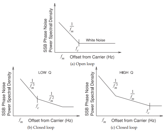
Figure \(\PageIndex{1}\): Log-log plot of oscillator noise spectra: (a) open-loop noise showing flicker noise \((1/f_{m})\) and white noise regions; (b) closed-loop noise with low-\(Q\) loop; and (c) closed-loop noise with high-\(Q\) loop.
the communication signal can be filtered out. Also phase noise slower than a few subharmonics below the symbol rate are compensated for in signal processing (e.g., using error correction codes).
Most RF oscillators comprise free-running oscillators whose oscillation frequency can be controlled by an applied DC or low-frequency voltage. Superior performance is obtained by comparing a scaled down version of an oscillator output to a high-precision reference oscillator such as a crystal oscillator. Without the feedback the oscillator is said to be an open-loop oscillator, and with feedback it is said to be a closed-loop oscillator.
For a free-running oscillator (i.e., an open-loop oscillator), the phase noise close to the carrier (i.e. the average oscillation frequency) is dominated by flicker phase noise, as shown in Figure \(\PageIndex{1}\)(a). This describes the intrinsic noise property of the active device (and surrounding circuitry) and the white noise and flicker noise responses are clearly seen. When the loop is closed, the loop transfer characteristic shapes the noise response, producing noise that has regions close to the carrier that has a \(1/f_{m}^{3}\) shape, and further from the carrier it varies as \(1/f_{m}^{2}\) if the \(Q\) of the loop is low [10]. The switch from \(1/f_{m}^{3}\) to \(1/f_{m}^{2}\) dependence is at what is called the transition or crossover frequency, \(f_{c}\) (see Figure \(\PageIndex{1}\)(b)). If the \(Q\) of the loop is high, the phase noise profile will transition from the \(1/f_{m}^{3}\) regime directly to the
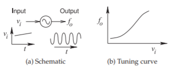
Figure \(\PageIndex{2}\): Voltage-controlled oscillator.
\(1/f_{m}\) regime, and again the transition frequency is \(f_{c}\) (see Figure \(\PageIndex{1}\)(c)). The transition frequency is usually around a few kilohertz to hundreds of kilohertz offset from the carrier for microwave transistors. A feedback analysis that describes how \(1/f\) and white noise are converted to the \(1/f_{m}^{3}\), \(1/f_{m}^{2}\), or \(1/f_{m}\) characteristics was developed by Leeson in 1966 [10] and others [11]. An advanced discussion of oscillator phase noise is given in Section 5.8 of [9] and the discussion here is limited but sufficient when using oscillators as modules. Here the traditional but approximate approach developed by Leeson is followed.
Phase noise was formally defined in Equation (4.4.3) and roughly it is the ratio of the phase noise power in a \(1\text{ Hz}\) bandwidth of a single sideband (SSB) to the total signal power. This is measured at a frequency \(f_{m}\) offset from the carrier and denoted \(\mathcal{L}(f_{m})\) with the units of \(\text{dBc/Hz}\) (i.e., decibels relative to the carrier power per hertz).
The phase noise that is important in RF and microwave oscillators (having relatively low \(Q\)) is usually dominated by a \(1/f_{m}^{2}\) shape. Then the phase noise at \(1\text{ MHz}\) (a common frequency for comparing the phase noise performance of different oscillators) is related to the phase noise measured at \(f_{m}\) by
\[\label{eq:1}\mathcal{L}(1\text{ MHz})=\mathcal{L}(f_{m})-10\log\left(\frac{1\text{ MHz}}{f_{m}}\right)^{2} \]
Another commonly used quantitative assessment of oscillator performance is provided by the oscillator figure of merit, \(\text{FOM}_{1}\), which accounts for the DC power consumed [12]:
\[\label{eq:2}\text{FOM}_{1}=\mathcal{L}(f_{m})-10\log\left(\frac{1\text{ MHz}}{f_{m}}\right)^{2}+10\log\left(\frac{P_{\text{DC}}}{P_{\text{ref}}}\right) \]
where \(P_{\text{ref}}\) is conventionally taken as \(1\text{ mW}\) and \(\text{FOM}_{1}\) is referenced to the phase noise at \(1\text{ MHz}\).