
6.3: Single-Ended, Balanced, and Double Balanced Mixers
- Page ID
- 46141
\( \newcommand{\vecs}[1]{\overset { \scriptstyle \rightharpoonup} {\mathbf{#1}} } \)
\( \newcommand{\vecd}[1]{\overset{-\!-\!\rightharpoonup}{\vphantom{a}\smash {#1}}} \)
\( \newcommand{\dsum}{\displaystyle\sum\limits} \)
\( \newcommand{\dint}{\displaystyle\int\limits} \)
\( \newcommand{\dlim}{\displaystyle\lim\limits} \)
\( \newcommand{\id}{\mathrm{id}}\) \( \newcommand{\Span}{\mathrm{span}}\)
( \newcommand{\kernel}{\mathrm{null}\,}\) \( \newcommand{\range}{\mathrm{range}\,}\)
\( \newcommand{\RealPart}{\mathrm{Re}}\) \( \newcommand{\ImaginaryPart}{\mathrm{Im}}\)
\( \newcommand{\Argument}{\mathrm{Arg}}\) \( \newcommand{\norm}[1]{\| #1 \|}\)
\( \newcommand{\inner}[2]{\langle #1, #2 \rangle}\)
\( \newcommand{\Span}{\mathrm{span}}\)
\( \newcommand{\id}{\mathrm{id}}\)
\( \newcommand{\Span}{\mathrm{span}}\)
\( \newcommand{\kernel}{\mathrm{null}\,}\)
\( \newcommand{\range}{\mathrm{range}\,}\)
\( \newcommand{\RealPart}{\mathrm{Re}}\)
\( \newcommand{\ImaginaryPart}{\mathrm{Im}}\)
\( \newcommand{\Argument}{\mathrm{Arg}}\)
\( \newcommand{\norm}[1]{\| #1 \|}\)
\( \newcommand{\inner}[2]{\langle #1, #2 \rangle}\)
\( \newcommand{\Span}{\mathrm{span}}\) \( \newcommand{\AA}{\unicode[.8,0]{x212B}}\)
\( \newcommand{\vectorA}[1]{\vec{#1}} % arrow\)
\( \newcommand{\vectorAt}[1]{\vec{\text{#1}}} % arrow\)
\( \newcommand{\vectorB}[1]{\overset { \scriptstyle \rightharpoonup} {\mathbf{#1}} } \)
\( \newcommand{\vectorC}[1]{\textbf{#1}} \)
\( \newcommand{\vectorD}[1]{\overrightarrow{#1}} \)
\( \newcommand{\vectorDt}[1]{\overrightarrow{\text{#1}}} \)
\( \newcommand{\vectE}[1]{\overset{-\!-\!\rightharpoonup}{\vphantom{a}\smash{\mathbf {#1}}}} \)
\( \newcommand{\vecs}[1]{\overset { \scriptstyle \rightharpoonup} {\mathbf{#1}} } \)
\(\newcommand{\longvect}{\overrightarrow}\)
\( \newcommand{\vecd}[1]{\overset{-\!-\!\rightharpoonup}{\vphantom{a}\smash {#1}}} \)
\(\newcommand{\avec}{\mathbf a}\) \(\newcommand{\bvec}{\mathbf b}\) \(\newcommand{\cvec}{\mathbf c}\) \(\newcommand{\dvec}{\mathbf d}\) \(\newcommand{\dtil}{\widetilde{\mathbf d}}\) \(\newcommand{\evec}{\mathbf e}\) \(\newcommand{\fvec}{\mathbf f}\) \(\newcommand{\nvec}{\mathbf n}\) \(\newcommand{\pvec}{\mathbf p}\) \(\newcommand{\qvec}{\mathbf q}\) \(\newcommand{\svec}{\mathbf s}\) \(\newcommand{\tvec}{\mathbf t}\) \(\newcommand{\uvec}{\mathbf u}\) \(\newcommand{\vvec}{\mathbf v}\) \(\newcommand{\wvec}{\mathbf w}\) \(\newcommand{\xvec}{\mathbf x}\) \(\newcommand{\yvec}{\mathbf y}\) \(\newcommand{\zvec}{\mathbf z}\) \(\newcommand{\rvec}{\mathbf r}\) \(\newcommand{\mvec}{\mathbf m}\) \(\newcommand{\zerovec}{\mathbf 0}\) \(\newcommand{\onevec}{\mathbf 1}\) \(\newcommand{\real}{\mathbb R}\) \(\newcommand{\twovec}[2]{\left[\begin{array}{r}#1 \\ #2 \end{array}\right]}\) \(\newcommand{\ctwovec}[2]{\left[\begin{array}{c}#1 \\ #2 \end{array}\right]}\) \(\newcommand{\threevec}[3]{\left[\begin{array}{r}#1 \\ #2 \\ #3 \end{array}\right]}\) \(\newcommand{\cthreevec}[3]{\left[\begin{array}{c}#1 \\ #2 \\ #3 \end{array}\right]}\) \(\newcommand{\fourvec}[4]{\left[\begin{array}{r}#1 \\ #2 \\ #3 \\ #4 \end{array}\right]}\) \(\newcommand{\cfourvec}[4]{\left[\begin{array}{c}#1 \\ #2 \\ #3 \\ #4 \end{array}\right]}\) \(\newcommand{\fivevec}[5]{\left[\begin{array}{r}#1 \\ #2 \\ #3 \\ #4 \\ #5 \\ \end{array}\right]}\) \(\newcommand{\cfivevec}[5]{\left[\begin{array}{c}#1 \\ #2 \\ #3 \\ #4 \\ #5 \\ \end{array}\right]}\) \(\newcommand{\mattwo}[4]{\left[\begin{array}{rr}#1 \amp #2 \\ #3 \amp #4 \\ \end{array}\right]}\) \(\newcommand{\laspan}[1]{\text{Span}\{#1\}}\) \(\newcommand{\bcal}{\cal B}\) \(\newcommand{\ccal}{\cal C}\) \(\newcommand{\scal}{\cal S}\) \(\newcommand{\wcal}{\cal W}\) \(\newcommand{\ecal}{\cal E}\) \(\newcommand{\coords}[2]{\left\{#1\right\}_{#2}}\) \(\newcommand{\gray}[1]{\color{gray}{#1}}\) \(\newcommand{\lgray}[1]{\color{lightgray}{#1}}\) \(\newcommand{\rank}{\operatorname{rank}}\) \(\newcommand{\row}{\text{Row}}\) \(\newcommand{\col}{\text{Col}}\) \(\renewcommand{\row}{\text{Row}}\) \(\newcommand{\nul}{\text{Nul}}\) \(\newcommand{\var}{\text{Var}}\) \(\newcommand{\corr}{\text{corr}}\) \(\newcommand{\len}[1]{\left|#1\right|}\) \(\newcommand{\bbar}{\overline{\bvec}}\) \(\newcommand{\bhat}{\widehat{\bvec}}\) \(\newcommand{\bperp}{\bvec^\perp}\) \(\newcommand{\xhat}{\widehat{\xvec}}\) \(\newcommand{\vhat}{\widehat{\vvec}}\) \(\newcommand{\uhat}{\widehat{\uvec}}\) \(\newcommand{\what}{\widehat{\wvec}}\) \(\newcommand{\Sighat}{\widehat{\Sigma}}\) \(\newcommand{\lt}{<}\) \(\newcommand{\gt}{>}\) \(\newcommand{\amp}{&}\) \(\definecolor{fillinmathshade}{gray}{0.9}\)Single-ended, balanced, and double-balanced diode mixers are shown in Figure \(\PageIndex{1}\). The simplest type of mixer that has been considered is the single-ended or unbalanced diode mixer of Figure 6.2.2(a). This is shown as a down-converting mixer where the RF signal at \(f_{\text{RF}}\) mixes with the LO at \(f_{\text{LO}}\) to produce a down-converted IF signal at \(f_{\text{LO}} − f_{\text{RF}}\). The image signal at \(f_{\text{LO}} + (f_{\text{LO}} − f_{\text{RF}})=2f_{\text{LO}} − f_{\text{RF}}\) will be down-converted to the same IF signal. It is of course not desirable to down-convert the image signal and it could be prevented by using filtering as shown, but the use of filters makes the filter quite large. There are many spurious frequencies with the single-ended mixer as seen in Figure 6.2.5. Most of these can be removed with filtering but using filters is undesirable and certainly not compatible with on-chip implementations. The solution is to use symmetry to cancel out many of the spurious tones. Figure \(\PageIndex{1}\)(b and c) shows two types of symmetry, balanced and double balanced mixers. Another level of symmetry could be used (applying it to the IF) in the double balanced mixer and then it could be called a triple balanced mixer. The triple balanced mixers is nearly always referred to as a double-balanced mixer. One cannot say whether a mixer is balanced, or even double balanced without tracing through the cancellation process. With each increasing degree of symmetry greater linearity of the conversion process is obtained. The double balanced mixer in FET form is particularly attractive as the FETs do not need to be biased. Except at very high millimeter-wave frequencies and terahertz frequencies, all mixers today are of the double or triple balanced form. However there can be unintentional mixing so the unbalanced mixer should be studied so that unwanted mixing can be identified.
RFIC Mixers
RFIC mixers below millimeter-wave frequencies utilize the transistor as a switch either with finite conductance when the switch closed and virtually zero conductance when the switch is open. The first mixer to be considered is based on the commutating mixer shown in Figure 6.2.12.
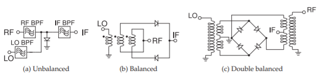
Figure \(\PageIndex{1}\): Unbalanced (also known as single-ended), balanced, and double-balanced downconversion diode mixersthat mix an LO with an RF to produce a lower frequency IF. bandpass filters.
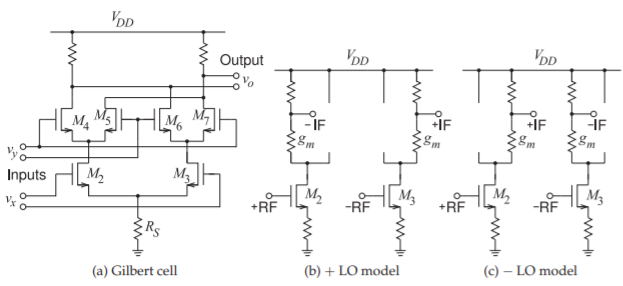
Figure \(\PageIndex{2}\): Model of the Gilbert cell and equivalent circuit models. The circuit is used as a mixer where \(v_{y}\) is the LO and \(v_{x}\) is the RF. (This is referred to as a double balanced mixer but strictly it is a triple balanced mixer as there are RF, IF, and LO symmetries resulting in a high level of cancellation of spurious tones.)
Gilbert Cell
The Gilbert cell builds on the commutating mixer circuit of Figure 6.2.2. The commutating mixer conducts current in the IF leg (with RIF during only half of the LO waveform. An immediate improvement is obtained by modifying the circuit to provide switched conductance during both halves of the LO waveform. Also, the RF and IF in the commutating mixer are single-ended quantities whereas with a silicon IC differential signals are preferred. The simplest Gilbert cell is shown in Figure \(\PageIndex{2}\)(a), which has all of the desired properties. \(M_{2}\) and \(M_{3}\) are designed as a differential amplifier pair with \(M_{4}\) and \(M_{5}\) functioning as time-varying loads for \(M_{2}\), and \(M_{6}\) and \(M_{7}\) function as time-varying loads for \(M_{3}\). This leads to the equivalent model of the Gilbert cell shown in Figures \(\PageIndex{2}\)(b and c).
The Gilbert cell is not always used as a mixer. If both \(v_{y}\) and \(v_{x}\) are small signals, then the Gilbert cell becomes a good analog multiplier with the output \(v_{o} = v_{x}\times v_{y}\). When used as a mixer, \(v_{y}\) is a large LO and the Gilbert cell is referred to as a Gilbert mixer. The Gilbert mixer is the functional core of virtually every integrated mixer, especially in CMOS technology where differential operation is preferred.
Integrated Gilbert Cell-Based Mixer
The performance of a Gilbert mixer is improved by replacing the source resistor, \(R_{S}\), of \(M_{2}\) and \(M_{3}\) in the basic Gilbert cell of Figure 6.2.2 with a current source, as shown in Figure \(\PageIndex{3}\)(a). This is the most common variation of the Gilbert mixer used in RFICs. A double-balanced Gilbert cell mixer is shown in Figure \(\PageIndex{3}\)(a). When the LO is small, the Gilbert mixer has an almost ideal multiplier response with performance limited by how closely the transistors can be matched [5]. In RFICs the transistors can be
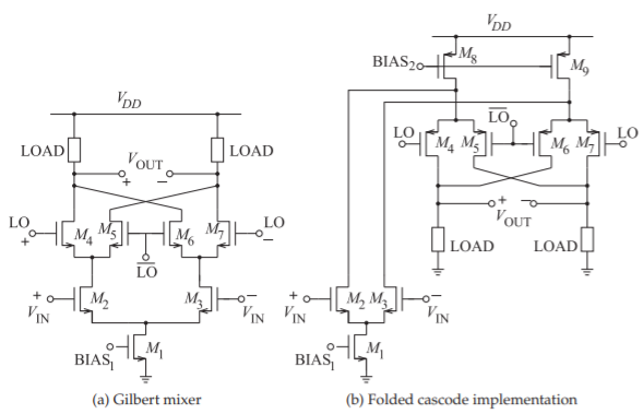
Figure \(\PageIndex{3}\): Gilbert cell double-balanced mixer.
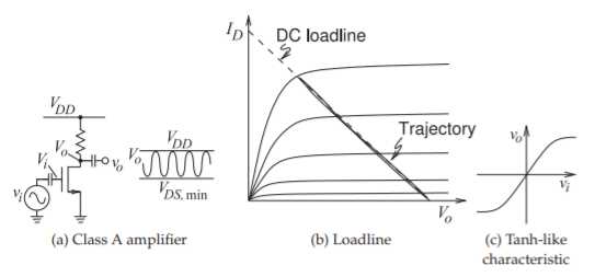
Figure \(\PageIndex{4}\): Simple transistor circuit (biasing not shown).
matched very well. When the LO is sufficiently large to produce a switching conductance, there is much greater tolerance to imperfect matching. This circuit has good performance and rejects RF and LO feed-through to the output, and the degree of rejection is dependent on the quality of the transistor match.
Before continuing the discussion the gross characteristics of a transistor circuit will be introduced. The simplest transistor circuit is the amplifier shown in Figure \(\PageIndex{4}\)(a). With an RF input signal, the large capacitor at the gate of the transistor becomes a short circuit and the trajectory of the transistor’s voltages and currents follows a load line as shown in Figure \(\PageIndex{4}\)(b). In the form of a transfer function, the characteristic of the amplifier is as shown in Figure \(\PageIndex{4}\)(c). This type of characteristic is typical of transistor circuits with the saturation levels of the output voltage set by the supply voltage and ground. The characteristic shown in Figure \(\PageIndex{4}\)(c) closely resembles the trigonometric tanh function and so the characteristic of a transistor circuit is often said to be tanh-like. A tanh-like response is also obtained with a Gilbert mixer circuit.
One problem with the Gilbert mixer circuit of Figure \(\PageIndex{3}\)(a) is the reduced voltage swing resulting from three drain-source voltage drops between the supply rails. The classic technique for solving this problem is to use a folded cascode design. The folded Gilbert cell double-balanced mixer then becomes the circuit of Figure \(\PageIndex{3}\)(b) [6, 7]. This merges a cascode amplifier design with the double-balanced Gilbert cell mixer in Figure \(\PageIndex{3}\)(a). The result is a mixer that can have a larger voltage swing.
Gilbert mixers, as enhanced so far, can have poor linearity in the sense that the IF output is linear only for small RF input signals. This problem is exasperated by the trend to reduce the supply voltage of integrated circuits. The solution used is to replace each of the amplifying transistors (\(M_{2}\) and \(M_{3}\) in Figures \(\PageIndex{3}\)(a and b)) by multiple transistors with progressively offset biasing that staggers the tanh-like transfer characteristic of a transistor circuit to realize an effective transistor with more linear characteristics [6, 8]. This design is used in the up-converting mixer shown in Figure \(\PageIndex{5}\), of a WCDMA transmitter RFIC. and the variation in biasing of the multiple amplifying transistors is achieved using sizing of each of the current source transistors in the bottom row. Alternatively, separate bias could be applied to each current source transistor. Also, the double-balanced Gilbert cell mixer in Figure \(\PageIndex{3}\)(a) is duplicated to realize a quadrature mixer.
The CMOS mixer has evolved from the core concept based on the diode ring mixer, first replacing the diodes by transistors, and then introducing transistor structures that cope with limited voltage supply and transistor nonidealities. This process is the essence of RF integrated circuit design.
Ring-Based Mixers
Diode ring mixers were discussed in Section 6.2.4 and circuit implementations were shown in Figures 6.2.9 and 6.2.10. Transistor-based mixer implementations using the ring mixer concept are shown in Figure \(\PageIndex{6}\).
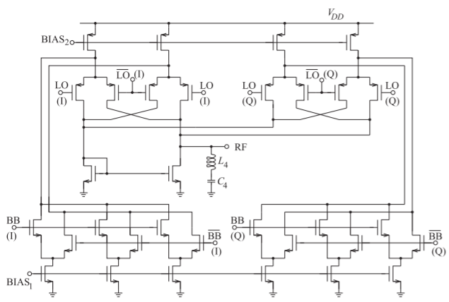
Figure \(\PageIndex{5}\): Quadrature up-converting mixer of a WCDMA transmitter. \(\text{BB}\) is the low-frequency baseband signal with (I) and (Q) components. \(\overline{\text{BB}}\) is the inverse (negative) of \(\text{BB}\). \(\text{LO}\) and \(\overline{\text{LO}}\) are the differential local oscillator signal, and \(\text{RF}\) is the single-ended output signal. The LO is at \(2\text{ GHz}\), the baseband input frequency is \(5\pm 1.72\text{ MHz}\), and the output frequency is \(1.95\text{ MHz}\). After Yang and Gard [6] and Yang [7]. Copyright K. Gard and X. Yang, used with permission.
Summary
| Mixer Type | Feature | Disadvantages |
|---|---|---|
| Unbalanced mixer | Very simple. Suitable for high millimeter-wave and terahertz frequencies. | Requires bulky filters to separate signals. Large spurious signals. |
| Single balanced mixer | Suppression of many spurious tones. Suppression of amplitude-modulated noise on LO. Increased linearity compared to unbalanced mixer. | Requires high LO drive level. |
| Double balanced mixer | Increased linearity compared to single-balanced mixer. All ports of the mixer are inherently isolated from each other. Can be implemented with passive mixing elements not requiring biasing. Inherently broadband. | Relies on symmetry and matched diodes and/or transistors. On RFIC calibration is used to balance mixer. |
| Triple balanced mixer | Provides increased linearity. The type most commonly used in RFICs although commonly referred to as a double balanced mixer. | Increasingly complex circuitry. |
Table \(\PageIndex{1}\)
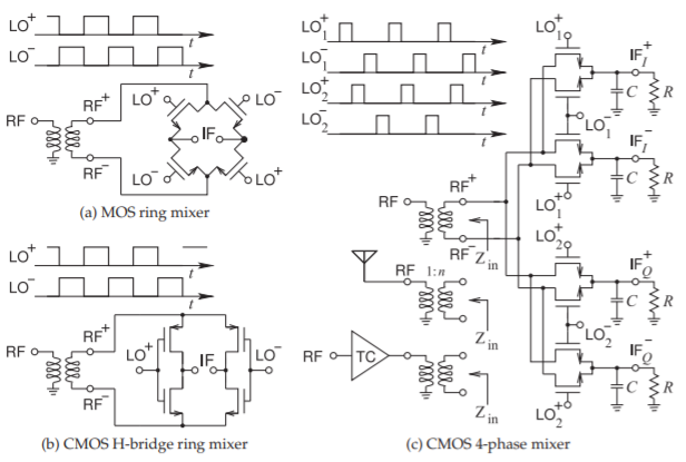
Figure \(\PageIndex{6}\): Transistor ring-type mixers.