
2.6: Frequency Shift Keying, FSK
- Page ID
- 41178

\( \newcommand{\vecs}[1]{\overset { \scriptstyle \rightharpoonup} {\mathbf{#1}} } \)
\( \newcommand{\vecd}[1]{\overset{-\!-\!\rightharpoonup}{\vphantom{a}\smash {#1}}} \)
\( \newcommand{\id}{\mathrm{id}}\) \( \newcommand{\Span}{\mathrm{span}}\)
( \newcommand{\kernel}{\mathrm{null}\,}\) \( \newcommand{\range}{\mathrm{range}\,}\)
\( \newcommand{\RealPart}{\mathrm{Re}}\) \( \newcommand{\ImaginaryPart}{\mathrm{Im}}\)
\( \newcommand{\Argument}{\mathrm{Arg}}\) \( \newcommand{\norm}[1]{\| #1 \|}\)
\( \newcommand{\inner}[2]{\langle #1, #2 \rangle}\)
\( \newcommand{\Span}{\mathrm{span}}\)
\( \newcommand{\id}{\mathrm{id}}\)
\( \newcommand{\Span}{\mathrm{span}}\)
\( \newcommand{\kernel}{\mathrm{null}\,}\)
\( \newcommand{\range}{\mathrm{range}\,}\)
\( \newcommand{\RealPart}{\mathrm{Re}}\)
\( \newcommand{\ImaginaryPart}{\mathrm{Im}}\)
\( \newcommand{\Argument}{\mathrm{Arg}}\)
\( \newcommand{\norm}[1]{\| #1 \|}\)
\( \newcommand{\inner}[2]{\langle #1, #2 \rangle}\)
\( \newcommand{\Span}{\mathrm{span}}\) \( \newcommand{\AA}{\unicode[.8,0]{x212B}}\)
\( \newcommand{\vectorA}[1]{\vec{#1}} % arrow\)
\( \newcommand{\vectorAt}[1]{\vec{\text{#1}}} % arrow\)
\( \newcommand{\vectorB}[1]{\overset { \scriptstyle \rightharpoonup} {\mathbf{#1}} } \)
\( \newcommand{\vectorC}[1]{\textbf{#1}} \)
\( \newcommand{\vectorD}[1]{\overrightarrow{#1}} \)
\( \newcommand{\vectorDt}[1]{\overrightarrow{\text{#1}}} \)
\( \newcommand{\vectE}[1]{\overset{-\!-\!\rightharpoonup}{\vphantom{a}\smash{\mathbf {#1}}}} \)
\( \newcommand{\vecs}[1]{\overset { \scriptstyle \rightharpoonup} {\mathbf{#1}} } \)
\( \newcommand{\vecd}[1]{\overset{-\!-\!\rightharpoonup}{\vphantom{a}\smash {#1}}} \)
\(\newcommand{\avec}{\mathbf a}\) \(\newcommand{\bvec}{\mathbf b}\) \(\newcommand{\cvec}{\mathbf c}\) \(\newcommand{\dvec}{\mathbf d}\) \(\newcommand{\dtil}{\widetilde{\mathbf d}}\) \(\newcommand{\evec}{\mathbf e}\) \(\newcommand{\fvec}{\mathbf f}\) \(\newcommand{\nvec}{\mathbf n}\) \(\newcommand{\pvec}{\mathbf p}\) \(\newcommand{\qvec}{\mathbf q}\) \(\newcommand{\svec}{\mathbf s}\) \(\newcommand{\tvec}{\mathbf t}\) \(\newcommand{\uvec}{\mathbf u}\) \(\newcommand{\vvec}{\mathbf v}\) \(\newcommand{\wvec}{\mathbf w}\) \(\newcommand{\xvec}{\mathbf x}\) \(\newcommand{\yvec}{\mathbf y}\) \(\newcommand{\zvec}{\mathbf z}\) \(\newcommand{\rvec}{\mathbf r}\) \(\newcommand{\mvec}{\mathbf m}\) \(\newcommand{\zerovec}{\mathbf 0}\) \(\newcommand{\onevec}{\mathbf 1}\) \(\newcommand{\real}{\mathbb R}\) \(\newcommand{\twovec}[2]{\left[\begin{array}{r}#1 \\ #2 \end{array}\right]}\) \(\newcommand{\ctwovec}[2]{\left[\begin{array}{c}#1 \\ #2 \end{array}\right]}\) \(\newcommand{\threevec}[3]{\left[\begin{array}{r}#1 \\ #2 \\ #3 \end{array}\right]}\) \(\newcommand{\cthreevec}[3]{\left[\begin{array}{c}#1 \\ #2 \\ #3 \end{array}\right]}\) \(\newcommand{\fourvec}[4]{\left[\begin{array}{r}#1 \\ #2 \\ #3 \\ #4 \end{array}\right]}\) \(\newcommand{\cfourvec}[4]{\left[\begin{array}{c}#1 \\ #2 \\ #3 \\ #4 \end{array}\right]}\) \(\newcommand{\fivevec}[5]{\left[\begin{array}{r}#1 \\ #2 \\ #3 \\ #4 \\ #5 \\ \end{array}\right]}\) \(\newcommand{\cfivevec}[5]{\left[\begin{array}{c}#1 \\ #2 \\ #3 \\ #4 \\ #5 \\ \end{array}\right]}\) \(\newcommand{\mattwo}[4]{\left[\begin{array}{rr}#1 \amp #2 \\ #3 \amp #4 \\ \end{array}\right]}\) \(\newcommand{\laspan}[1]{\text{Span}\{#1\}}\) \(\newcommand{\bcal}{\cal B}\) \(\newcommand{\ccal}{\cal C}\) \(\newcommand{\scal}{\cal S}\) \(\newcommand{\wcal}{\cal W}\) \(\newcommand{\ecal}{\cal E}\) \(\newcommand{\coords}[2]{\left\{#1\right\}_{#2}}\) \(\newcommand{\gray}[1]{\color{gray}{#1}}\) \(\newcommand{\lgray}[1]{\color{lightgray}{#1}}\) \(\newcommand{\rank}{\operatorname{rank}}\) \(\newcommand{\row}{\text{Row}}\) \(\newcommand{\col}{\text{Col}}\) \(\renewcommand{\row}{\text{Row}}\) \(\newcommand{\nul}{\text{Nul}}\) \(\newcommand{\var}{\text{Var}}\) \(\newcommand{\corr}{\text{corr}}\) \(\newcommand{\len}[1]{\left|#1\right|}\) \(\newcommand{\bbar}{\overline{\bvec}}\) \(\newcommand{\bhat}{\widehat{\bvec}}\) \(\newcommand{\bperp}{\bvec^\perp}\) \(\newcommand{\xhat}{\widehat{\xvec}}\) \(\newcommand{\vhat}{\widehat{\vvec}}\) \(\newcommand{\uhat}{\widehat{\uvec}}\) \(\newcommand{\what}{\widehat{\wvec}}\) \(\newcommand{\Sighat}{\widehat{\Sigma}}\) \(\newcommand{\lt}{<}\) \(\newcommand{\gt}{>}\) \(\newcommand{\amp}{&}\) \(\definecolor{fillinmathshade}{gray}{0.9}\)Frequency shift keying (FSK) is one of the simplest forms of digital modulation, with the frequency of the transmitted signal at a clock tick indicating a symbol, usually representing either one or two bits. Binary FSK (BFSK) is illustrated in Figure 2.5.2(d). It can be implemented by applying a discrete signal to the input of a voltage-controlled oscillator and so was ideally suited to early digital radio as simple high-performance FM modulators were available. Four-state FSK modulation is used in the GSM 2G cellular standard, a legacy standard still widely supported by modern cellular radios and sometimes the only modulation supported by the infrastructure (i.e. basestations) in some regions where it is not economically viable to retrofit old installations.
2.6.1 Essentials of FSK Modulation
The schematic of a binary FSK modulation system is shown in Figure \(\PageIndex{1}\). Here, a binary bitstream is lowpass filtered and used to drive an FSK modulator, one implementation of which shifts the frequency of an oscillator according to the voltage of the baseband signal. This function can be achieved using a VCO or a PLL circuit, and an FM demodulator can be used to receive the signal. Another characteristic feature of FSK is that the amplitude of the modulated signal is constant, so efficient saturating (and hence nonlinear) amplifiers can be used without the concern of frequency distortion. Not surprisingly, FSK was the first form of digital modulation used in mobile digital radio. A particular implementation of FSK is Minimum Shift Keying (MSK), which uses a baseband lowpass filter so that the transitions from one state to another are smooth in time and limit the bandwidth of the modulated signal.
The constellation diagram is often thought of as being like a phasor diagram and this analogy works most of the time but it does not work for FSK modulation. A phasor diagram describes a phasor that is fixed in frequency. If the phasor is very slowly phase and/or amplitude modulated, then this approximation is good. FSK modulation cannot be represented on a phasor diagram, as the information is in the frequency at the clock ticks and not the than the phase and/or amplitude of a phasor. The symbols of two-and four-state FSK modulation are shown in Figure \(\PageIndex{2}\) which are called constellation diagrams.
As an example consider an FSK-modulated signal with a bandwidth of \(200\text{ kHz}\) and a carrier at \(1\text{ GHz}\) (this approximately corresponds to the 2G GSM cellular system). This is a \(0.02\%\) bandwidth, so the phasor changes very slowly. Going from one FSK state to another takes about \(1230\) to \(3692\)
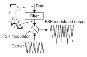
Figure \(\PageIndex{1}\): The frequency shift keying (FSK) modulation system. In the GSM four-state cellular system-adjacent constellation points differ in frequency by \(33.25\text{ kHz}\).
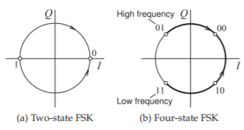
Figure \(\PageIndex{2}\): Constellation diagrams of FSK modulation. In two-state FSK a symbol indicates whether a bit is a ’\(0\)’ or a ’\(1\)’. In four-state FSK there are four symbols and each symbol has a different frequency and indicates the values of two bits.
RF cycles depending on the frequency difference of the transition from one symbol to the next. With a \(1\text{ GHz}\) carrier the frequencies of the four symbols are \((1\text{ GHz} − 33.25\text{ kHz}),\: (1\text{ GHz} − 16.62\text{ kHz}),\: (1\text{ GHz} + 16.62\text{ kHz}),\) and \((1\text{ GHz} + 33.25\text{ kHz})\). This may seem like a very small frequency difference but hardware in the basestation and in the handset can easily achieve a frequency resolution of a few hertz at \(1\text{ GHz}\). In trying to represent FSK modulation on a pseudo-phasor diagram, the frequency is approximated as being fixed and the maximum real frequency shift is arbitrarily taken as being a significant shift of the pseudo-phasor.
In FSK, the states are on a circle in the constellation diagram (see Figure \(\PageIndex{2}\)), with two-state FSK shown in Figure \(\PageIndex{2}\)(a) and four-state FSK shown in Figure \(\PageIndex{2}\)(b). Note that the constellation diagram indicates that the amplitude of the phasor is constant, as FSK modulation is a form of FM modulation. Consider four-state FSK more closely. There are four frequency states ranging from the low-frequency state to the high-frequency state as shown in Figure \(\PageIndex{2}\)(b). In four-state FSK modulation a transition from the low-frequency state to the high-frequency state takes three times longer than a transition between adjacent states. While the ‘\(01\)’ and ‘\(11\)’ states appear to be adjacent, in reality the frequency transition must traverse through the other frequency states. Filtering of the baseband modulating signal is required to minimize the bandwidth of the modulated four-state FSK signal. This reduces modulation efficiency to less than the theoretical maximum of \(2\text{ bits/s/Hz}\).
In summary, there are slight inconsistencies and arbitrariness in using a phasor diagram for FSK, but FSK does have a defined constellation diagram that is closely related, but not identical, to a phasor diagram. Another difference is that a phasor diagram depends on the amplitude of the RF signal, while a constellation diagram is continuously being re-normalized to the average RF power level to maintain a constant size. With FSK modulation almost the entire modulation and demodulation paths can be implemented using analog circuitry and so was ideally suited to early cellular radios.
2.6.2 Gaussian Minimum Shift Keying
Gaussian minimum shift keying (GMSK) is the modulation scheme used in the GSM cellular wireless system and is a variant of MSK with waveform shaping coming from a Gaussian lowpass filter. It is a particular implementation of FSK modulation.
The modulation efficiency of GMSK as implemented in the GSM system (it depends slightly on the Gaussian filter parameters) is \(1.35\text{ bits/s/Hz}\). Unfiltered MSK has a constant RF envelope. However filtering is required to limit the RF bandwidth and this results in amplitude variations of about \(30\%\). This is still very little so one of the fundamental advantages of this modulation scheme is that nonlinear, power-efficient amplification can be used. GMSK is essentially a digital implementation of FM with discrete changes in the frequency of modulation with the input bitstream filtered so that the change in frequency from one state to the next is smooth. It is only at the clock ticks that the modulated signal must have the specified discrete frequency. The phase of the modulating signal is always continuous and there is no information in the phase of the modulated signal.
The ideal transitions in FSK follow a circle from one state to another as shown in Figure \(\PageIndex{2}\) so that the PMEPR of ideal FSK is \(0\text{ dB}\). With GMSK the transitions do not follow a circle because of the filtering and the transitions also overshoot. As such the amplitude of a GMSK modulated signal varies and the PMEPR of GMSK is \(3.01\text{ dB}\). This is the PMEPR for a single modulated carrier, combining multiple modulated carriers as done in a basestation increases the PMEPR. Statistically the envelopes are less likely to all align if there are multiple carriers. For example, with multi-carrier \(\text{GMSK, PMEPR }= 3.01\text{ dB},\: 6.02\text{ dB},\: 9.01\text{ dB},\: 11.40\text{ dB},\: 14.26\text{ dB},\) and \(17.39\text{ dB}\) for \(1,\: 2,\: 4,\: 8,\: 16,\) and \(32\) carriers respectively. (These values were calculated numerically by simulating a multi-carrier system.)
GMSK and other FSK methods have the advantage that implementation of the baseband and RF hardware is relatively simple. A GMSK transmitter can use conventional frequency modulation. On receive, an FM discriminator, i.e. an FM receiver with sampling, can be used avoiding more complex \(I\) and \(Q\) demodulation.
2.6.3 Doppler Effect
Frequency is a physical parameter that can be established and measured with great accuracy, down to a few hertz at \(1\text{ GHz}\) in a mobile handset for example. Thus if a receiver is stationary the frequency states at the clock ticks of an FSK modulated carrier can be measured with great accuracy. When a receiver and transmitter are moving relative to each other there will be a Doppler shift of the carrier frequency. If the relative velocity of the receiver and transmitter is \(v_{s}\) the Doppler shift will be
\[\label{eq:1}\Delta f=fv_{s}/c \]
where \(f\) is the frequency of the radio transmission and \(c\) is the speed of light. For a receiver moving at \(100\text{ km/hr}\) receiving a \(1\text{ GHz}\) signal from a fixed transmitter, the Doppler frequency shift is \(\Delta f = 92.6\text{ Hz}\) which is much less than the \(33\text{ kHz}\) frequency spacing of adjacent states in the FSK example above. Thus the Doppler shift is not of concern. This effective fixing of the constellation points is one of the advantages of GSM.
2.6.4 Summary
GSM was not the only 2G system. The 2G NADC (for North American Digital Cellular) system modulated the phase of a carrier using phase shift keying. The NADC cellular system had higher modulation efficiency than GSM yet MSK became the dominant 2G system and is still supported as a legacy modulation system in modern cellular radio. The main reason for this is that GSM was more closely aligned with the business interests of the telephone operators of the day.