
5.8: 5G, Fifth Generation Radio
- Page ID
- 41222

\( \newcommand{\vecs}[1]{\overset { \scriptstyle \rightharpoonup} {\mathbf{#1}} } \)
\( \newcommand{\vecd}[1]{\overset{-\!-\!\rightharpoonup}{\vphantom{a}\smash {#1}}} \)
\( \newcommand{\id}{\mathrm{id}}\) \( \newcommand{\Span}{\mathrm{span}}\)
( \newcommand{\kernel}{\mathrm{null}\,}\) \( \newcommand{\range}{\mathrm{range}\,}\)
\( \newcommand{\RealPart}{\mathrm{Re}}\) \( \newcommand{\ImaginaryPart}{\mathrm{Im}}\)
\( \newcommand{\Argument}{\mathrm{Arg}}\) \( \newcommand{\norm}[1]{\| #1 \|}\)
\( \newcommand{\inner}[2]{\langle #1, #2 \rangle}\)
\( \newcommand{\Span}{\mathrm{span}}\)
\( \newcommand{\id}{\mathrm{id}}\)
\( \newcommand{\Span}{\mathrm{span}}\)
\( \newcommand{\kernel}{\mathrm{null}\,}\)
\( \newcommand{\range}{\mathrm{range}\,}\)
\( \newcommand{\RealPart}{\mathrm{Re}}\)
\( \newcommand{\ImaginaryPart}{\mathrm{Im}}\)
\( \newcommand{\Argument}{\mathrm{Arg}}\)
\( \newcommand{\norm}[1]{\| #1 \|}\)
\( \newcommand{\inner}[2]{\langle #1, #2 \rangle}\)
\( \newcommand{\Span}{\mathrm{span}}\) \( \newcommand{\AA}{\unicode[.8,0]{x212B}}\)
\( \newcommand{\vectorA}[1]{\vec{#1}} % arrow\)
\( \newcommand{\vectorAt}[1]{\vec{\text{#1}}} % arrow\)
\( \newcommand{\vectorB}[1]{\overset { \scriptstyle \rightharpoonup} {\mathbf{#1}} } \)
\( \newcommand{\vectorC}[1]{\textbf{#1}} \)
\( \newcommand{\vectorD}[1]{\overrightarrow{#1}} \)
\( \newcommand{\vectorDt}[1]{\overrightarrow{\text{#1}}} \)
\( \newcommand{\vectE}[1]{\overset{-\!-\!\rightharpoonup}{\vphantom{a}\smash{\mathbf {#1}}}} \)
\( \newcommand{\vecs}[1]{\overset { \scriptstyle \rightharpoonup} {\mathbf{#1}} } \)
\( \newcommand{\vecd}[1]{\overset{-\!-\!\rightharpoonup}{\vphantom{a}\smash {#1}}} \)
\(\newcommand{\avec}{\mathbf a}\) \(\newcommand{\bvec}{\mathbf b}\) \(\newcommand{\cvec}{\mathbf c}\) \(\newcommand{\dvec}{\mathbf d}\) \(\newcommand{\dtil}{\widetilde{\mathbf d}}\) \(\newcommand{\evec}{\mathbf e}\) \(\newcommand{\fvec}{\mathbf f}\) \(\newcommand{\nvec}{\mathbf n}\) \(\newcommand{\pvec}{\mathbf p}\) \(\newcommand{\qvec}{\mathbf q}\) \(\newcommand{\svec}{\mathbf s}\) \(\newcommand{\tvec}{\mathbf t}\) \(\newcommand{\uvec}{\mathbf u}\) \(\newcommand{\vvec}{\mathbf v}\) \(\newcommand{\wvec}{\mathbf w}\) \(\newcommand{\xvec}{\mathbf x}\) \(\newcommand{\yvec}{\mathbf y}\) \(\newcommand{\zvec}{\mathbf z}\) \(\newcommand{\rvec}{\mathbf r}\) \(\newcommand{\mvec}{\mathbf m}\) \(\newcommand{\zerovec}{\mathbf 0}\) \(\newcommand{\onevec}{\mathbf 1}\) \(\newcommand{\real}{\mathbb R}\) \(\newcommand{\twovec}[2]{\left[\begin{array}{r}#1 \\ #2 \end{array}\right]}\) \(\newcommand{\ctwovec}[2]{\left[\begin{array}{c}#1 \\ #2 \end{array}\right]}\) \(\newcommand{\threevec}[3]{\left[\begin{array}{r}#1 \\ #2 \\ #3 \end{array}\right]}\) \(\newcommand{\cthreevec}[3]{\left[\begin{array}{c}#1 \\ #2 \\ #3 \end{array}\right]}\) \(\newcommand{\fourvec}[4]{\left[\begin{array}{r}#1 \\ #2 \\ #3 \\ #4 \end{array}\right]}\) \(\newcommand{\cfourvec}[4]{\left[\begin{array}{c}#1 \\ #2 \\ #3 \\ #4 \end{array}\right]}\) \(\newcommand{\fivevec}[5]{\left[\begin{array}{r}#1 \\ #2 \\ #3 \\ #4 \\ #5 \\ \end{array}\right]}\) \(\newcommand{\cfivevec}[5]{\left[\begin{array}{c}#1 \\ #2 \\ #3 \\ #4 \\ #5 \\ \end{array}\right]}\) \(\newcommand{\mattwo}[4]{\left[\begin{array}{rr}#1 \amp #2 \\ #3 \amp #4 \\ \end{array}\right]}\) \(\newcommand{\laspan}[1]{\text{Span}\{#1\}}\) \(\newcommand{\bcal}{\cal B}\) \(\newcommand{\ccal}{\cal C}\) \(\newcommand{\scal}{\cal S}\) \(\newcommand{\wcal}{\cal W}\) \(\newcommand{\ecal}{\cal E}\) \(\newcommand{\coords}[2]{\left\{#1\right\}_{#2}}\) \(\newcommand{\gray}[1]{\color{gray}{#1}}\) \(\newcommand{\lgray}[1]{\color{lightgray}{#1}}\) \(\newcommand{\rank}{\operatorname{rank}}\) \(\newcommand{\row}{\text{Row}}\) \(\newcommand{\col}{\text{Col}}\) \(\renewcommand{\row}{\text{Row}}\) \(\newcommand{\nul}{\text{Nul}}\) \(\newcommand{\var}{\text{Var}}\) \(\newcommand{\corr}{\text{corr}}\) \(\newcommand{\len}[1]{\left|#1\right|}\) \(\newcommand{\bbar}{\overline{\bvec}}\) \(\newcommand{\bhat}{\widehat{\bvec}}\) \(\newcommand{\bperp}{\bvec^\perp}\) \(\newcommand{\xhat}{\widehat{\xvec}}\) \(\newcommand{\vhat}{\widehat{\vvec}}\) \(\newcommand{\uhat}{\widehat{\uvec}}\) \(\newcommand{\what}{\widehat{\wvec}}\) \(\newcommand{\Sighat}{\widehat{\Sigma}}\) \(\newcommand{\lt}{<}\) \(\newcommand{\gt}{>}\) \(\newcommand{\amp}{&}\) \(\definecolor{fillinmathshade}{gray}{0.9}\)As with 4G there will be long term evolution of the 5G standard and this will be upwards compatible with 4G. Even though 4G was touted as the long term evolution of 3G, at the physical layer it was fundamentally incompatible. 5G is fundamentally compatible with 4G at the physical layer and it is expected that cellular phone services will continue to function much the same as if 4G was being used. The first iteration (i.e. evolution) of 5G is called Next Radio (NR) and begins with 3GPP Release 15, see Figure 5.9.4, and operation began in the second half of 2018.
The full 5G standard supports three use cases and a significantly improved level of service over 4G. One of the uses cases is enhanced mobile broadband (eMBB) with peak data rates of \(20\text{ Gbit/s}\) and sustained data rates of \(100\text{ Mbit/s}\). High mobility of up to \(500\text{ km/s}\) is supported. Another use case is massive machine-to-machine communication (mMTC) supporting the internet of things (IoT) with high density of devices (up to \(10^{6}/\text{km}^{2}\), long range, low data rate \((1\text{ kbit/s}–100\text{ kbit/s})\), and enabling \(10\) year battery life. The third use case is ultra reliability and low latency (URLLC) with less than \(1\text{ ms}\) air interface latency and less than \(5\text{ ms}\) overall end-to-end latency, \(99.9999\%\) reliability, data rates up to \(10\text{ Mbit/s}\), and supporting high mobility.
Many scenarios require ultra-reliable and very low end-to-end latency, perhaps as low as \(1\text{ ms}\). The early deployments of 4G had latencies of \(80\text{ ms}\) or more and varied considerable across service providers. Over the years since 4G was launched latencies have reduced considerably but in 4G it is not possible to have air-interface latencies less than the \(10\text{ ms}\) frame rate of 4G. A fundamental limit in 4G is due to the \(0.5\text{ ms}\) time duration of a slot, see Figure 5.9.6. One concept in 5G is to have more slots per \(1\text{ ms}\) subframe maintaining the subframe for upwards compatibility. In 4G there are two slots per subframe. Possible developments in 5G are \(1\)) to have more slots per subframe and \(2\)) (what seems to be similar) to have more symbols per slot. With \(16\) slots per subframe the slot duration is \(0.0625\text{ ms}\). The long-term evolution of 5G will continue and achieve overall latencies of \(1\text{ ms}\) or less.
An important concept of 5G is to be fully compatible with the 4G infrastructure and the only new infrastructure required is that to support new services. There were two central ideas behind 4G: OFDM and MIMO and these are used in 5G OFDM. OFDM in 4G used two fixed sub-carrier spacing, but 5G has a number of different sub-carrier bandwidths including a subchannel bandwidth of \(480\text{ kHz}\), and a low bandwidth subchannel bandwidth of \(7.5\text{ kHz}\) to accommodate high speed mobility As with 4G, carrier aggregation is used but now the bitstreams on up to \(32\) carriers are combined. Also channel bandwidths are up to \(400\text{ MHz}\) compared to the \(20\text{ MHz}\) RF bandwidth maximum of 4G.
5.11.1 Mesh Radio
In 5G a wireless mesh removes the need for a fixed basestation to communicate directly to an end unit [32]. If there is a node between the basestation and a mobile user, an intervening node, possibly another mobile user, can be used effectively as a relay. This reduces overall power requirements and levels of interference, which in turn leads to greater data carrying capacity. This concept can be extended to use multiple intervening nodes forming a dense mesh with considerable tolerance to multipath and interference effects. One significant benefit of this can be seen by noting that in an urban environment power can fall off by the fourth power of distance. Another benefit is that the impact of fading can be greatly reduced, as the paths in the mesh will fade independently. This will be augmented by many small cells called femtocells and picocells handling traffic in small geographic areas such as buildings, airports, and sporting facilities.
5.11.2 Cognitive Radio
Cognitive radio exploits the fact that much of the EM spectrum remains unused even while the bands reserved for cellular communications have reached capacity. This situation is a consequence of the allocation of bands for dedicated services that may not be active at a particular time and place. Examples are unused bands reserved for broadcast television channels and bands reserved for communication in times of emergencies. A cognitive radio senses its environment and adapts in real time to a user’s communication needs by temporarily borrowing unused spectrum [33, 34]. As a result spectrum is used more efficiently. A cognitive radio avoids causing interference with the communications of other users by sensing spectrum use, changing frequency, adjusting power level, and altering transmission protocols. If a licensed band is borrowed, then a cognitive radio discontinues use of this part of the spectrum if the licensee of the band becomes active. This behavior is also called dynamic spectrum management.
5.11.3 Massive MIMO
MIMO in 4G uses multiple antennas at the basestation and at terminals to increase overall data rates provided that there are multiple paths between the transmitter and receiver. For example, with two basestation antennas transmitting separate bitstreams but in the same frequency band and two uncorrelated receive antennas, known as \(2\times 2\) MIMO, the theoretical maximum data rate is twice what could be supported by line-of-sight communication. In 5G there can be a very large number of transmit antennas even though there are few receiver antennas per terminal unit as multiple terminal units mean that there can effectively be a very large number of receive antennas.
5G operates at frequencies below \(6\text{ GHz}\) and at millimeterwave frequencies. Below \(6\text{ GHz}\) \(8\times 8\) MIMO is supported in the standard but there can be a hundred or more basestation antennas. For example. With \(128\) basestation antennas and four receiver antennas per terminal unit, \(32\) terminal units can be supported in the same frequency band. Overall the system has much higher throughput, theoretically a maximum of \(128\) times more than a single line-of-sight link could support. This concept, i.e. not all of the receive antennas need be on the same platform, is called massive MIMO.
Massive MIMO uses characterization of the channel as in conventional MIMO but uses this information to form multiple beams each directed at each terminal unit. This situation is shown in Figure \(\PageIndex{1}\) where there are multiple transmit/receive antennas at each basestation but relatively
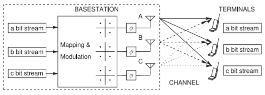
Figure \(\PageIndex{1}\): A massive MIMO system with beams from the basestation antennas to each terminal unit.
few transmit/receive antennas at each terminal unit. At the start of each correlation interval, i.e. the time over which a channel does not change significantly, each terminal unit transmits a code to the basestation. Each terminal unit uses an orthogonal code and so the basestation is able to characterize the channels from each of the terminal units to the basestation. The basestation is then able to use its antennas in a phased array to form a beam to transmit data just to the intended terminal. The real situation is a little different as a single beam is not formed but instead a weighted signal is broadcast from each of the basestation antennas with the effect being that all of the power following multiple paths comes together at the intended terminal unit. Still this process is called beamforming. Different beams are used for each basestation. In the second half of the correlation interval the terminal unit transmits back to the basestation and the basestation uses its beamforming in reverse to effectively create multiple receive beams each directed at a terminal units. Of course these are not strictly beams but use the channel model to combine the signals from each of the basestation receive antennas to effectively receive signals with the highest signal-to-interference ration from each terminal.
Massive MIMO has a performance advantage even with line-of-sight as long as the terminal units are not on top of each other as the paths from each of the basestation antennas to each of the terminals will be uncorrelated. Beam steering can be also used to concentrate transmitted energy in a particular direction.
5.11.4 Active Antenna Systems
Adaptive antennas, or active antenna systems (AAS), are also known as smart antennas and adapt an array of antennas to either direct an antenna beam between a transmitter and a receiver, eliminate interference, or use the spatial signatures provided by diverse propagation paths to transfer more information than can be sent over a single link [35]. All this is done using signal processing rather than hardware reconfiguration.
In one approach a smart antenna is used to switch between a number of fixed, usually narrow, antenna beams in what is analogous to a highly sectored antenna array. Switching requires knowledge of the angle of arrival and the beams track a mobile unit. A simple version of this concept is used in 3G and 4G radio. As well as focusing the available power on the intended communication nodes, beam forming through beam switching also minimizes interference.
Adaptive antennas increase data transfer rates, reduce interference, and reduce the amount of transmit power required.
5.11.5 Microwave Frequency Operation
Low frequency operation refers to 5G operating below \(6\text{ GHz}\). The bands being adopted for early stage deployment are the \(700\text{ MHz}\), \(3300–4200\text{ MHz}\) and \(4400–5000\text{ MHz}\) bands but the full coverage is not available in all countries. Many are predicting that the bulk of 5G communication will be at these frequencies, particularly at \(3.5\text{ GHz}\), up until the mid or late 2020s. It is important to 5G that there be globally available spectrum. The \(700\text{ MHz}\) band is of particular interest as it will provide wide area coverage and deep penetration into buildings and so is a candidate for providing high reliability links important for the 5G mMTC applications. At this frequency 5G is compatible with 4G but with evolved characteristics such as supporting up to \(32\) carrier aggregation and \(8\times 8\) MIMO instead of the five carrier aggregation and (usually) maximum \(3\times 3\) MIMO of 4G. Also 5G in the low frequency range supports 256 QAM modulation but then the order of QAM modulation supported with 4G has evolved with latter 3GPP releases.
5.11.6 Millimeter-Wave Operation
The very high data rates of 5G are obtained by operating at millimeterwave (mm-wave) frequencies where much more bandwidth is available. The bands being focused on are the \(24.25–29.5\text{ GHz}\) and \(37–40.5\text{ GHz}\). (Yes, technically \(24.25–29.5\text{ GHz}\) is not millimeter-waves which requires a wavelength to be \(10\text{ mm}\) or less, but that is being called mm-waves in the 5G community.) At mm-wave frequencies very tight beamforming can be achieved if the same overall antenna size is used. However there is a penalty, signal attenuation is high and it is not possible to send signals through walls and into buildings. As such window mounted units are required to receive signals. Millimeter-wave operation is envisioned to use \(2\times 2\) MIMO only, but still use massive MIMO, be useful for low speed mobility, but provide very high data rates.
5.11.7 Non Orthogonal Multiple Access
One of the distinguishing features of 4G and 5G is OFDMA, an orthogonal multiple access (OMA) scheme. OFDMA in (both both 4G and) 5G allocates a dedicated resource block to each user and orthogonality ensures that there is almost no inter-user interference. The system utilization is optimum when each resource block is fully utilized. However this is not the case with IoT devices, the support for which is one of the main features of 5G. When IoT devices communicate very little information is usually exchanged and so most of the resource block used by an IoT device is unused. The expected growth of 5G will see a great proliferation of IoT devices with these devices having diverse data rate and latency requirements. Communicating with each IoT device by allocating a dedicated resource block does not use the capacity effectively. In addition, using the same basestation transmit power for each user is said to be ‘unfair’ in that each user typically has a different channel quality with a user having a poorer channel quality needing to operate with lower-order modulation. The ‘unfairness’ arises because the channel capacity is not equally shared but it would be if the the basestation transmitted higher powers to the user with a poorer channel. Non orthogonal multiple access (NOMA) is designed to addresses this imbalance and to ensure optimum use of each resource block and hence of the communication system.
The key concept of NOMA is that low-rate devices will share a resource block, they will use differing symbol rates, and the transmit power level from the basestation to each user will be adjusted according to the quality of the communication channel [36, 37]. In NOMA, and in contrast to OFDMA, there will be inter-user interference and schemes have been developed that will enable individual users to be separated. One possible NOMA scheme to separate users by using code domain multiplexing with each user sharing a resource block being assigned a unique code. The concept is very similar to that used in WCDMA but applied at the level of a resource block.
The dominant NOMA scheme in 5G and the one to be first deployed (as of the time of writing this book) in a future 3GPP release of the 5G standard is multi-user superposition transmission (MUST). Successive interference cancelation (SIC) is the scheme used to separate users.
In MUST users are allocated different power levels and will use different symbol rates. For example, a distant user with a poor quality channel will receive more power in NOMA and a user with a good channel will receive less since the maximum power available from the basestation transmitter is fixed. The result is that the throughput of the close and distant users will be similar. This is called ‘fairness’ and is particularly important when the system is operating at or near capacity. A further advantage of NOMA is that the demands on the basestation transmitter hardware is reduced. One of the consequences of having a common symbol rate in OFDMA is that the PMEPR is higher than it would be if there was a range of symbol rates. Thus NOMA will result in the total RF signal being transmitted from the basestation having a lower PMEPR.
It is expected that there will be a significant increase in throughput as many users, think of IoT devices, only need to communicate at very low data rates. Current cellular systems reach an abrupt limit on their throughput. In NOMA overload is supported at the cost of inter-user interference. Studies have shown that a threefold increase incapacity is possible with NOMA schemes that tolerate overload and inter-user interference [37].
5.11.8 Summary
The 5G system introduces many system optimization strategies and a highlevel of system optimization across perhaps hundreds of basestations is required to achieve full potential. The 5G systems will inevitably be followed by 6G and this is the subject of current research. The defining characteristic is that 6G is being targeted to operate above \(100\text{ GHz}\) and provide enormous bandwidths since very wide bandwidths are available.