
5.7: 4G, Fourth Generation Radio
- Page ID
- 41221

The 4G cellular system provides downlink data rates of \(100\text{ Mbit/s}\) while mobile and \(1\text{ Gbit/s}\) while stationery. The uplink data rates are much lower at \(50\text{ Mbit/s}\). The maximum rates are assigned to a cellular service area and are shared but rely on a user’s average data rate being much lower. Providing these data rates relies on a number of significant advances over 3G:
- Orthogonal frequency division multiplexing (OFDM). Using a very large number of narrowband channels, e.g. \(1200\), with each narrowband channel having the highest-order modulation possible. Each narrowband channel has its own subcarrier which is individually modulated. Gets around the multipath problem where poor channel characteristics affecting a narrow range of frequencies does not limit overall bit rates.
- High-order modulation. A terminal unit supports a very large number of modulation formats, several PSK modulation methods and QAM methods ranging from 16-QAM to 1024-QAM. Modulation and demodulation are implemented in a DSP unit.
- Cyclic prefix (CP). Enables the use of efficient discrete Fourier transforms in the transmitter. Simplifies hardware by yielding lower PMEPR than would be obtained if a zero-level guard band was provided to overcome interference caused by multipath.
- Multiple input, multiple output (MIMO). MIMO uses multiple antennas to transmit and receive signals exploiting independent transmit-receive paths to increase the total capacity between a basestation and terminal unit. Multiplies data rates by the number of transmit or receive antennas (which ever is less).
- Pervasive access. Terminal units support many access technologies (e.g., 2G–4G, WiFi, Bluetooth etc.) and seamlessly switching among them. Since 4G is an IP-based system data can be sent on any network, e.g. WiFi utilization reduces the demands on the cellular network.
These advances require tremendous computing power made available by advanced low-power VLSI and developments in low-power RF modems. Another critical aspect of 4G (and now 5G) is deployment of a well thought out road map called Long Term Evolution (LTE) that enables incremental (although significant) advances building on previously implemented enhancements.
The LTE timeline is shown in Figure 5.9.4, 4G effectively began with Release-9 implemented first at the end of 2010 with this release introducing MIMO and OFDM (to be defined latter). There are fundamental changes to the physical interface, and 4G uses Internet Protocal (IP) exclusively including for voice (voice over IP—VoIP). Subsequent releases introduced more concepts and increased data coverage. 4G and now 5G can not coexist with 3G systems and separate bands must be allocated. Eventually 3G will go away. It is worth noting that 5G is upwards compatible with 4G.
The ITU World Radiocommunication Conference has allocated many bands to 4G ranging from \(450\text{ MHz}\) to \(5850\text{ MHz}\). There is not a single band that can be used world-wide but cellular handsets are designed to support
| Band | Mode | Uplink \((\text{MHz})\) | Downlink \((\text{MHz})\) | Bandwidths \((\text{MHz})\) | Regions |
|---|---|---|---|---|---|
| \(3\) | FDD | \(1710-1755\) | \(1805-1880\) | \(1.4, 3, 5, 10, 15, 20\) | Asia, Parts of Africa, Europe, Parts of Latin America, Oceania |
| \(12\) | FDD | \(699-716\) | \(729-746\) | \(1.4, 3, 5, 10\) | North America, Asia, Parts of Africa, Europe, Parts of Latin America |
| \(40\) | TDD | \(2300-2400\) | \(5, 10, 15, 20\) | Asia, Parts of Europe, Oceania | |
| \(41\) | TDD | \(2496-2690\) | \(5, 10, 15, 20\) | Parts of Africa, Parts of Asia, USA | |
Table \(\PageIndex{1}\): Selected LTE bands used in 4G.
| Bandwidth | Resource blocks | Subcarriers (downlink) | Subcarriers (uplink) |
|---|---|---|---|
| \(1.4\text{ MHz}\) | \(6\) | \(73\) | \(72\) |
| \(3\text{ MHz}\) | \(15\) | \(181\) | \(180\) |
| \(5\text{ MHz}\) | \(25\) | \(301\) | \(300\) |
| \(10\text{ MHz}\) | \(50\) | \(601\) | \(600\) |
| \(15\text{ MHz}\) | \(75\) | \(901\) | \(900\) |
| \(20\text{ MHz}\) | \(100\) | \(1201\) | \(1200\) |
Table \(\PageIndex{2}\): Resources for different LTE bandwidths.
Figure \(\PageIndex{1}\): OFDM spectrum with four subcarriers showing orthogonality.
multiple bands. The features of representative bands are shown in Table \(\PageIndex{1}\). Channel bandwidth, with a channel having a single carrier, range from \(1.4\text{ MHz}\) to \(20\text{ MHz}\), see Table \(\PageIndex{2}\). Each carrier has correlated subcarriers each modulated to produce a subchannel with a \(15\text{ kHz}\)-wide bandwidth.
5.10.1 Orthogonal Frequency Division Multiplexing
In OFDM, data is divided into many bitstreams with each bitstream modulating a subcarrier producing a relatively narrowband subchannel and a user being assigned multiple subchannels. In 4G these subchannels are 15 kHz-wide in normal operation and \(7.5\text{ kHz}\) wide in a rich multipath environment with a large excess delay spread as described in Section 4.7. The concept behind this is that having a narrow bandwidth, the duration of a symbol is long and will exceed the excess delay spread. This minimizes the impact of intersymbol interference (ISI) when a symbol traveling on a fast path overlaps with the component of a previous symbol traveling on a longer path. Also each subchannel can be modulated with the maximum order modulation enabled by that particular channel’s characteristics. For this to work the subcarriers must be orthogonal and precisely spaced in frequency and time. The orthogonality is shown in the spectrum of Figure \(\PageIndex{1}\), where the arrows at the top indicate sampling points for two subcarriers. The orthogonality of the subcarriers is seen by noticing that the peak of one subcarrier is at the zeros of the other subcarriers. When one subcarrier is sampled, the contribution from all other carriers is zero; they are orthogonal. The spectra of the subcarriers overlap, but this does not matter.
In 4G groups of \(12\) subcarriers lasting \(0.5\text{ ms}\) are grouped in a resource block which is the minimal allocation to a user. In communications with a handset, a basestation (called a B node in 4G and 5G) allocates a specific number of subcarriers. These may not be contiguous on the downlink, as shown in Figure 5.4.1(d), but are contiguous on the uplink. The number of subcarriers allocated to a particular user varies according to the data rate requirements and the order of modulation used with each subcarrier being adjusted to accommodate the subchannel characteristics including fading and interference.
In communicating to a single user, the total bitstream is error encoded and then the bitstream is divided up so that different parts of the bitstream are sent over multiple subchannels thus spreading the coded data. As a result 4G implements spectrum spreading but at a much lower coding rate than the spreading in 3G. This further mitigates the impact of multipath which can affect the integrity of individual subchannels. Signal strength and interference, and hence SIR, can differ for each channel and this is compensated for by having different bit rates in each subchannel and spreading the data plus error correction coding.
A second effect of multipath is referred to as delay spread. Transmitted signal components following different paths arrive at a receiver at different times. If the time duration of a symbol is short, which is the case if wideband modulation is used, then the components of a signal, corresponding to one symbol, following longer paths could arrive at the same time as the components of the next symbol following shorter paths. This causes intersymbol interference. With the longer symbol duration with OFDM and a guard band interval (which is now relatively short) between symbols, intersymbol interference can be greatly reduced.
Implementation
OFDM could be implemented by using separate modulators and demodulators for each subcarrier. Instead the separate modulators and demodulators are replaced by a fast Fourier transform (FFT) and an inverse FFT (iFFT), respectively, implemented in a DSP unit called the baseband processor. In the transmitter the iFFT produces a modulated signal at a low intermediate carrier frequency. For example, a \(1.4\text{ MHz}\) bandwidth OFDM signal could be a DSB-SC signal with a center frequency, i.e. IF carrier frequency, of \(700\text{ kHz}\) but otherwise look identical to the final transmitted OFDM signal. Then a SSB-SC up-converter translates the OFDM signal to a radio frequency signal. Each of the time-varying frequency inputs of the iFFT is centered at a subcarrier frequency. Each of the frequency inputs is a sequence of time-samples of a slowly varying modulated signal implementing the selected modulation method for that subchannel. On receive the input of the FFT is the sequence of time samples of the modulated signal centered on the IF carrier which has been down-converted from RF. Each of the outputs of the FFT correspond to a time sample of an individual modulated subcarrier.
Since the OFDM signal combines many individually modulated subcarriers the PMEPR of OFDM is large but grows relatively slowly with the number of subcarriers. The higher PMEPR, compared to a single modulated carrier, introduces microwave design challenges especially for mixers and amplifiers.
Figure \(\PageIndex{2}\): Components of a frame in 4G for a \(1.4\text{ MHz}\)-bandwidth channel. The \(10\text{ ms}\) long frame, top left, has an array of resource blocks each with a slot duration of \(0.5\text{ ms}\) and a bandwidth of \(180\text{ kHz}\). This frame has a \(1.08\text{ MHz}\) data bandwidth with \(160\text{ kHz}\) guard bands for a total bandwidth of \(1.4\text{ MHz}\). (The guard-band differs for channels having other bandwidths. Each resource block has on seven OFDM symbols with each comprised of seven symbols during a symbol interval. There are \(84\) symbols (Seven OFDM symbols) per resource block (with 1024- QAM having \(10\text{ bits}\) per subcarrier \(840\text{ bits}\) are transmitted per resource block).
However, since most of the heavy lifting is done in DSP which being numerical is distortion-free, the up-converter is simplified.
Resource Blocks
The way that OFDM is implemented in 4G is illustrated in Figure \(\PageIndex{2}\) for a \(1.4\text{ MHz}\)-bandwidth modulated signal. The subchannels in 4G are organized in a frame that is \(10\text{ ms}\) long. Within the frame subchannels are grouped into resource blocks each of which has a duration of \(0.5\text{ ms}\) and a bandwidth of \(180\text{ kHz}\). The resource block is the smallest unit allocated to a user and a user can have many simultaneous resource blocks and many sequential resource blocks. A resource black has many subcarriers and symbol intervals and the exact length and bandwidth of a single symbol-subcarrier segment has a normal mode used most of the time, and two extended modes that handle severe multipath environments. In the normal mode, each resource block has seven \(71.4\:\mu\text{s}\)-long symbols per subcarrier and there are \(12\) subcarriers. (The extended modes have longer symbol duration and \(7.5\text{ kHz}\) bandwidth.)
In OFDM there are subchannels that are reserved for pilot tones that send known data streams and these can be used to characterize the channel. The pilot subchannels are denoted as \(\mathsf{P}\) in Figure 5.4.1(d). The dedicated pilot subchannels enable carrier recovery. Therefore it is not necessary to restrict modulation by avoiding transitions through the origin of the constellation diagram (or more precisely the phasor of the modulated subcarrier). Thus near-ideal modulation efficiency is possible for the data subcarriers.
Summary
OFDM has been tremendously successful and only had to wait for the capabilities of low-power VLSI to advance. It is now widely used in communications including WiFi, wired communications (e.g. digital subscriber line (DSL)) as well as in 4G and 5G.
5.10.2 Orthogonal Frequency Division Multiple Access
Orthogonal Frequency division multiple access (OFDMA), also known as multiuser OFDM, is the multiuser version of OFDM that supports simultaneous communication by multiple users and so is an access technology. The access scheme is illustrated in Figure 5.4.1(d) where one channel is illustrated and could have a bandwidth ranging from \(1.4\text{ MHz}\) to \(20\text{ MHz}\). There could be \(1201\) subchannels so not all of these are shown. The subchannels are grouped in contiguous groups of \(12\) subchannels to form a \(1\text{ ms}\)-long resource block (\(24\) \(7.5\text{ kHz}\)-wide subchannels in extended mode used with a very rich multipath environment). So what are numbered in Figure 5.4.1(d) are resource blocks. In OFDMA, generally one or more resource blocks are assigned to a particular user and these do not need to be contiguous in the downlink but are contiguous in the uplink as then the PMEPR is lower.
This lessens the demand on the power amplifier in the terminal unit. Effectively there is a single carrier on the uplink and hence the uplink access scheme is also called single-carrier frequency division multiple access (SC-FDMA) or single-carrier orthogonal frequency division multiple access (SC-OFDMA). On the downlink the basestation is using all of the subchannels simultaneously communicating with multiple terminal units but in the uplink each terminal unit only uses a few. Users share pilot subchannels, designated as \(\mathsf{P}\) in Figure 5.4.1(d).
5.10.3 Cyclic Prefix
The cyclic prefix (CP) refers to the scheme used to accommodate excess delay spread resulting from multipath. Since symbols sent on different paths arrive at the receive antenna with various delays, there can be overlap of a symbol arriving on a fast path with a previous symbol arriving on a longer path. This could result in intersymbol interference (ISI). In 4G there could have been a zeroed (i.e. no signal) guard interval to eliminate ISI. Instead, in 4G, a cyclic prefix (CP) is used whereby a symbol is prefixed repeating the end part of a symbol. One symbol of a resource block is shown at the bottom of Figure \(\PageIndex{2}\). Each symbol of the resource block is \(66.7\:\mu\text{s}\) long with a cylic prefix which normally is \(4.7\:\mu\text{s}\) long but longer for the first symbol of the resource block and when in extended mode which is used in severe multipath environments.\(^{1}\) The \(4.7\:\mu\text{s}\) long CP corresponds to a
Figure \(\PageIndex{3}\): Duplex schemes used in 4G with ten subframes in a \(10\text{ ms}\) frame.
difference in path lengths of \(1.4\text{ km}\). This cyclic prefix provides the required guard interval. There are several advantages to copying the end of a symbol and repeating it before the symbol. This reduces the PMEPR that would result if the guard interval had no signal, and it enables a discrete Fourier transform to be used in processing the signal. This is essential to efficient VLSI implementation of OFDM.
The repetition of the cyclic prefix for each symbol in a resource block is equivalent to repeating the end of each OFDM symbol at the start of an OFDM symbol (the aggregate of symbols across all \(12\) subcarriers constitutes an OFDM symbol). The repetition enables the start of each OFDM symbol to be determined as the CP is correlated to the end of the symbol. The cyclic prefix also helps in characterizing the channel and removing distortion within the OFDM symbol.
5.10.4 FDD versus TDD
Frequency division duplex (FDD) and time division duplex (TDD) are two duplex schemes supported in 4G although only one mode or the other is supported in a particular band, e.g. see Table \(\PageIndex{1}\). FDD and TDD are arranged in frames of \(10\text{ ms}\) comprising ten subframes of \(1\text{ ms}\) duration, see Figure \(\PageIndex{3}\). In FDD, Figure \(\PageIndex{3}\)(a), there are separate uplink, denoted \(\mathsf{U}\), and downlink, denoted \(\mathsf{D}\), frequency bands and uplink and downlink transmissions are simultaneous. The use of paired spectrum requires a good diplexer to isolate the receiver and transmitter. In TDD, Figure \(\PageIndex{3}\)(b), uplink and downlink use the same band and there are separate uplink, denoted \(\mathsf{U}\), and downlink, denoted \(\mathsf{D}\), transmissions in different frequency bands. In TDD, uplink and downlink transmissions are simultaneous. Channel propagation is the same in both directions at least over \(10\text{ ms}\) as long as mobility is not too high. TDD allows dynamic allocation of uplink and downlink capacity.
5.10.5 Multiple Input, Multiple Output
Multiple input, multiple output (MIMO, pronounced my-moe) technology uses multiple antennas to transmit and receive signals. The MIMO concept was developed in the 1990s [27, 28] and implemented in 4G and 5G, and several WLAN systems. There are several aspects to MIMO. First, each transmit antenna sends different data streams simultaneously on the same frequency channel as other transmit antennas. The most interesting feature
Figure \(\PageIndex{4}\): A MIMO system showing multiple paths between each transmit antenna and each receive antenna.
is that MIMO relies on signals traveling on multiple paths between an array of transmit antennas and an array of receive antennas. In a conventional communications system the various paths result in interference and fading, but in MIMO these paths are used to carry more information. In a MIMO system, each path propagates an image of one transmitted signal (from one antenna) that differs in both amplitude and phase from the images following other paths. Effectively there are multiple connections between each transmit antenna and each receive antenna, see Figure \(\PageIndex{4}\). For simplicity, three transmit antennas and three receive antennas are shown. However, MIMO can work with as few as two transmit antennas and two receive antennas. In MIMO a high-speed data-stream is split into several slower data streams, shown in Figure \(\PageIndex{4}\) as the \(\mathsf{a}\), \(\mathsf{b}\), and \(\mathsf{c}\) bitstreams. The distinct bitstreams are separately modulated and sent from their own transmit antenna, with the constellation diagrams of the transmitted modulated signals labeled \(\mathsf{A}\), \(\mathsf{B}\), and \(\mathsf{C}\). The signals from each of the transmit antenna reaches all of the receive antennas by following different uncorrelated paths.
The output of each receive antenna is a linear combination of the multiple transmitted data streams, with the sampled RF phasor diagrams labeled \(\mathsf{M}\), \(\mathsf{N}\), and \(\mathsf{O}\). (It is not really appropriate to call these constellation diagrams.) That is, each receive antenna has a different linear combination of the multiple images. In effect, the output from each receive antenna can be thought of as the solution of linear equations, with each transmit antenna-receive antenna link corresponding to an equation. Continuing the analogy, the signal from each transmit antenna represents a variable. So a set of simultaneous equations can be solved to obtain the original bitstreams. This is accomplished by demodulation and mapping using knowledge of the channel characteristics to yield the original transmitted signals modified by interference. The result is that the constellation diagrams \(\mathsf{W}\), \(\mathsf{X}\), and \(\mathsf{Y}\) are obtained. The composite channel can be characterized using known test signals. Special coding called space-time (or spatio-temporal) coding embedded in the transmitted data-stream also enables estimation of the communication matrix. Space-time coding encodes each transmitted data-stream with information that can be used to update the channel characterization.
The capacity of a MIMO system with high SIR scales approximately linearly with the minimum of \(M\) and \(N\), \(\text{min}(M,N)\), where \(M\) is the number
| Modulation scheme | Capacity \(\text{bits/s/Hz}\) (bits per second per hertz) | ||||
|---|---|---|---|---|---|
| MIMO with \(M=2, N=2\) | |||||
| SIR \(0\text{ dB}\) | SIR \(10\text{ dB}\) | SIR \(20\text{ dB}\) | SIR \(30\text{ dB}\) | ||
| BPSK | \(1\) | \(1.2\) | \(2\) | \(2\) | \(2\) |
| QPSK | \(2\) | \(1.6\) | \(3.7\) | \(4\) | \(4\) |
| 8-PSK | \(3\) | \(1.6\) | \(4.8\) | \(6\) | \(6\) |
| 16-PSK | \(4\) | \(1.6\) | \(4.9\) | \(7.5\) | \(8\) |
Table \(\PageIndex{3}\): Capacity of MIMO schemes with PSK modulation for different received SIRs compared to the maximum capacity of a conventional non-MIMO scheme. \(M\) is the number of transmit antennas, \(N\) is the number of receive antennas. Data from [31].
of transmit antennas and \(N\) is the number of receive antennas (provided that there is a rich set of paths) [29, 30]. So a system with \(M = N = 4\) will have four times the capacity of a system with just one transmit antenna and one receive antenna. Table \(\PageIndex{3}\) presents the capacity of a MIMO system with ideal PSK modulation and two transmit and two receive antennas. This is compared to the capacity of a conventional (non-MIMO) system. The capacity is presented in bits per second per hertz and it is seen that significant increases in throughput are obtained when SIR is high. MIMO is a successful way to increase capacity and is included in modern WiFi, radars, and other communication systems.
In summary, MIMO systems achieve throughput and range improvements through four gains achieved simultaneously:
- Array gain resulting from increased average received SIR obtained by coherently combining signals. To exploit this the channel must be characterized. This increases coverage and quality of service (QoS).
- Diversity gain obtained by presenting the receiver with multiple identical copies of a given signal. This combats fading. This also increases coverage and QoS.
- Multiplexing gain by transmitting independent data signals from different antennas to increase throughput. This increases spectral efficiency.
- Cochannel interference reduction. This increases cellular capacity.
5.10.6 Carrier Aggregation
Carrier aggregation (CA) is one of the main features that 4G introduced. In carrier aggregation bitstreams on different carriers are combined to yield a higher overall bit rate than one carrier can support. This enables shortterm high bit rates to be transmitted to a terminal. The full concept supports combining of bit-streams with carriers that are in different frequency bands (called inter-band CA), the same frequency band (called intra-band CA), different cells, and even in a combination of licensed and unlicensed (think WiFi) bands. It is 4G LTE-A combining carrier aggregation and MIMO that achieves, and can even surpass, the peak \(1\text{ Gbit/s}\) goal of 4G. A typical goal of 4G LTE A is to combine five carriers. The 4G standards, 3GPP release \(13\), supports \(32\)-carrier aggregation and up to \(3\text{ Gbit/s}\).
5.10.7 IEEE 802.11n
The IEEE 802.11n WiFi system is not 4G but this is discussed here to indicate that many of the concepts that are incorporated in wireless systems
| MCS index | Spatial streams | Modulation type | Coding rate \(R_{i}/R_{c}\) | Data rate \((\text{Mbit/s})\) | |||
|---|---|---|---|---|---|---|---|
| \(20\text{ MHz}\) channel | \(40\text{ MHz}\) channel | ||||||
| \(800\text{ ns}\) GI | \(400\text{ ns}\) GI | \(800\text{ ns}\) GI | \(400\text{ ns}\) GI | ||||
| \(0\) | \(1\) | BPSK | \(1/2\) | \(6.50\) | \(7.20\) | \(13.50\) | \(15.00\) |
| \(1\) | \(1\) | QPSK | \(1/2\) | \(13.00\) | \(14.40\) | \(27.00\) | \(30.00\) |
| \(2\) | \(1\) | QPSK | \(3/4\) | \(19.50\) | \(21.70\) | \(40.50\) | \(45.00\) |
| \(3\) | \(1\) | 16-QAM | \(1/2\) | \(26.00\) | \(28.90\) | \(54.00\) | \(60.00\) |
| \(4\) | \(1\) | 16-QAM | \(3/4\) | \(39.00\) | \(43.30\) | \(81.00\) | \(90.00\) |
| \(5\) | \(1\) | 64-QAM | \(2/3\) | \(52.00\) | \(57.80\) | \(108.00\) | \(120.00\) |
| \(6\) | \(1\) | 64-QAM | \(3/4\) | \(58.50\) | \(65.00\) | \(121.50\) | \(135.00\) |
| \(7\) | \(1\) | 64-QAM | \(5/6\) | \(65.00\) | \(72.20\) | \(135.00\) | \(150.00\) |
| \(8\) | \(2\) | BPSK | \(1/2\) | \(13.00\) | \(14.40\) | \(27.00\) | \(30.00\) |
| \(9\) | \(2\) | QPSK | \(1/2\) | \(26.00\) | \(28.90\) | \(54.00\) | \(60.00\) |
| \(10\) | \(2\) | QPSK | \(3/4\) | \(39.00\) | \(43.30\) | \(81.00\) | \(90.00\) |
| \(11\) | \(2\) | 16-QAM | \(1/2\) | \(52.00\) | \(57.80\) | \(108.00\) | \(120.00\) |
| \(12\) | \(2\) | 16-QAM | \(3/4\) | \(78.00\) | \(86.70\) | \(162.00\) | \(180.00\) |
| \(13\) | \(2\) | 64-QAM | \(2/3\) | \(104.00\) | \(115.60\) | \(216.00\) | \(240.00\) |
| \(14\) | \(2\) | 64-QAM | \(3/4\) | \(117.00\) | \(130.00\) | \(243.00\) | \(270.00\) |
| \(15\) | \(2\) | 64-QAM | \(5/6\) | \(130.00\) | \(144.40\) | \(270.00\) | \(300.00\) |
| \(16\) | \(3\) | BPSK | \(1/2\) | \(19.50\) | \(21.70\) | \(40.50\) | \(45.00\) |
| \(17\) | \(3\) | QPSK | \(1/2\) | \(39.00\) | \(43.30\) | \(81.00\) | \(90.00\) |
| \(18\) | \(3\) | QPSK | \(3/4\) | \(58.50\) | \(65.00\) | \(121.50\) | \(135.00\) |
| \(19\) | \(3\) | 16-QAM | \(1/2\) | \(78.00\) | \(86.70\) | \(162.00\) | \(180.00\) |
| \(20\) | \(3\) | 16-QAM | \(3/4\) | \(117.00\) | \(130.70\) | \(243.00\) | \(270.00\) |
| \(21\) | \(3\) | 64-QAM | \(2/3\) | \(156.00\) | \(173.30\) | \(324.00\) | \(360.00\) |
| \(22\) | \(3\) | 64-QAM | \(3/4\) | \(175.50\) | \(195.00\) | \(364.50\) | \(405.00\) |
| \(23\) | \(3\) | 64-QAM | \(5/6\) | \(195.00\) | \(216.70\) | \(405.00\) | \(450.00\) |
| \(\cdots\) | \(4\) | \(\cdots\) | \(\cdots\) | \(\cdots\) | \(\cdots\) | \(\cdots\) | \(\cdots\) |
| \(31\) | \(4\) | 64-QAM | \(5/6\) | \(260.00\) | \(288.90\) | \(540.00\) | \(600.00\) |
Table \(\PageIndex{4}\): Data rates used in the 802.11n standard. MCS is the modulation and coding scheme index. GI is the guard interval. With a \(20\text{ MHz}\)-wide channel there are \(52\) data subcarriers, and an additional \(4\) subcarriers, called pilots, enable carrier recovery and monitor the channel characteristics. With a \(40\text{ MHz}\)-wide channel there are \(108\) data subcarriers and \(6\) pilot subcarriers. \(R_{i} =\) information bit rate, \(R_{c} =\) coded bit rate. \(R_{c}\) is the bit rate of information bits plus bits added for error correction. Thus a coding rate of \(5/6\) means that for every \(5\) information bits there is an additional (redundant) code bit.
first appear in WiFi. IEEE 802.11n is an example of a data communication system that combines many advanced concepts. The 802.11n system uses MIMO, OFDM, and many dedicated subcarriers for continuous channel characterization and carrier recovery. The 802.11n standard uses several modulation types, as shown in Table \(\PageIndex{4}\), and it supports the use of either a \(20\text{ MHz}\)- or \(40\text{ MHz}\)-wide channel. There can be one, two, three or four spatial streams and these are equal to the minimum of the number of transmit and receive antennas. If the number of transmit or receive antennas is more than the number of spatial streams, the extra antennas are used for receiver or transmit diversity. Under the best conditions with high SNR, negligible correlation of the transmit-to-receive antenna paths, and four transmit and four receive antennas, the modulation and coding scheme (MCS) index \(31\) is used. With this index, modulation uses 64-QAM and \(5/6\)
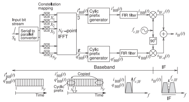
Figure \(\PageIndex{5}\): Block diagram of an OFDM modulator.
coding. This mode supports a data rate of \(600\text{ Mbit/s}\) if a \(400\text{ ns}\) guard interval is used. This guard interval, rather than the 800 ns guard interval, is used when there is low delay spread. If the SNR is lower, a lower-order modulation scheme is used.
5.10.8 OFDM Modulator
The basic structure of an OFDM modulator is shown in Figure \(\PageIndex{5}\). From the perspective of a single user, a bitstream \(S_{k}\) is divided up by a serial-to-parallel converter to produce multiple slower bitstreams each of which is mapped onto complex signals \(x_{i}\) which become the frequency inputs of an iFFT. The outputs of the iFFT are real and imaginary time-domain baseband signals \(i_{\text{BB}}′(t)\) and \(q_{\text{BB}}′(t)\). At each symbol interval \((i_{\text{BB}}′(t),\: q_{\text{BB}}′(t))\) indicates a symbol. The \(i_{\text{BB}}′(t)\) and \(q_{\text{BB}}′(t)\) pass through a cyclic prefix generator that copies the end of the symbol and prefixes it to the beginning of the symbol. Then the output of the cyclic prefix generators are shaped by an FIR filter (generally a raised cosine filter) to produce the shaped I/Q signals \(i_{\text{BB}}(t)\) and \(q_{\text{BB}}(t)\) which are input to a quadrature modulator with an intermediate carrier frequency to produce a DSB-SC intermediate frequency signal modulated signal \(s_{\text{IF}}(t)\). For example, if the frequency range of \(i_{\text{BB}}(t)\) and \(q_{\text{BB}}(t)\) range from just above DC to just below \(700\text{ kHz}\) the choice of \(f_{c,\text{ IF}} = 700\text{ kHz}\) results in a \(1.4\text{ MHz}\) wide modulated signal \(s_{\text{IF}}(t)\) which is a DSB-SC OFDM modulated signal. The entirety of the OFDM modulator in Figure \(\PageIndex{5}\) is implemented digitally in a DSP unit.
5.10.9 Summary of 4G
At the physical layer the 4G standard introduces and combines OFDM, carrier aggregation (CA), and MIMO to achieve tremendous data rates that,
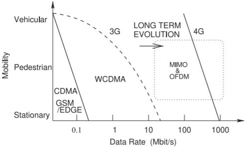
Figure \(\PageIndex{6}\): Data rate capacity of 4G as the long term evolution of 3G.
in a fully implemented 4G system achieves low-latency data download at mobile rates up to \(100\text{ Mbit/s}\) and rates while stationary of \(1\text{ Gbit/s}\). OFDM is the technology that sends many relatively slow bitstreams over narrow bandwidth sub-channels to efficiently support multiple users making best use of the channels available and circumventing many multipath effects. It replaces the use of spreading codes in CDMA to support multiple access and circumvent some multipath problems. CA combines multiple bitsteams sent on different carriers and even from different basestations to increase the short term overall bit rate. MIMO uses multiple, i.e. \(M\), transmit antennas, at the basestation, and multiple, i.e. \(N\), receive antennas, at the handset, and exploits uncorrelated communication paths between pairs of transmit and receive antennas. The (ideally) zero correlation is made possible by multipath and the correlation is lowest if there is no line-of-sight path. If the de-correlation is complete the data capacity is increased by a function of the minimum of the number of transmit antennas, i.e. \(\text{MIN}(M,N)\). If there is some correlation, perhaps due to coupling between the receive antennas, then a MIMO capacity factor \(H ≤ \text{MIN}(M,N)\) is defined. With MIMO it is necessary to modify Shannon’s capacity limit as MIMO systems can exceed the limit defined for a single channel. Shannon’s capacity limit for a MIMO system becomes [29]
\[\label{eq:1}\hat{C}=B_{c}\log_{2}(1+\text{SIR}\cdot H) \]
This indicates that the channel carrying capacity is greatly increased, especially when the SIR is high. The data rate capacity of 2G systems (GSM and CDMA) is contrasted with the capacity of 3G (WCDMA) and 4G systems in Figure \(\PageIndex{6}\).
Footnotes
[1] In the normal mode the first CP is \(5.2\:\mu\text{s}\) long and there are two extended modes. One is \(16.7\:\mu\text{s}\) long and another is \(33.3\:\mu\text{s}\) long and then the bandwidth of each subchannel is reduced to \(7.5\text{ kHz}\). In normal mode the overhead is \(7\%\) and in extended mode the CP overhead is \(25\%\). If the first extended CP is used then there are \(6\) OFDM symbols per resource block.