
4.13: Exercises
- Page ID
- 46058
\( \newcommand{\vecs}[1]{\overset { \scriptstyle \rightharpoonup} {\mathbf{#1}} } \) \( \newcommand{\vecd}[1]{\overset{-\!-\!\rightharpoonup}{\vphantom{a}\smash {#1}}} \)\(\newcommand{\id}{\mathrm{id}}\) \( \newcommand{\Span}{\mathrm{span}}\) \( \newcommand{\kernel}{\mathrm{null}\,}\) \( \newcommand{\range}{\mathrm{range}\,}\) \( \newcommand{\RealPart}{\mathrm{Re}}\) \( \newcommand{\ImaginaryPart}{\mathrm{Im}}\) \( \newcommand{\Argument}{\mathrm{Arg}}\) \( \newcommand{\norm}[1]{\| #1 \|}\) \( \newcommand{\inner}[2]{\langle #1, #2 \rangle}\) \( \newcommand{\Span}{\mathrm{span}}\) \(\newcommand{\id}{\mathrm{id}}\) \( \newcommand{\Span}{\mathrm{span}}\) \( \newcommand{\kernel}{\mathrm{null}\,}\) \( \newcommand{\range}{\mathrm{range}\,}\) \( \newcommand{\RealPart}{\mathrm{Re}}\) \( \newcommand{\ImaginaryPart}{\mathrm{Im}}\) \( \newcommand{\Argument}{\mathrm{Arg}}\) \( \newcommand{\norm}[1]{\| #1 \|}\) \( \newcommand{\inner}[2]{\langle #1, #2 \rangle}\) \( \newcommand{\Span}{\mathrm{span}}\)\(\newcommand{\AA}{\unicode[.8,0]{x212B}}\)
- Section 4.2.1 presented the harmonic balance equations for the analysis of a nonlinear resistor. DC, the fundamental, and the second harmonic were retained. Derive the harmonic balance equations if only the DC and fundamental tones are retained in the analysis. That is, derive the analysis in Section 4.2.1. You do not need to implement the computer program to perform the analysis.
- A new digital modulation scheme produces a signal with a PMEPR of \(5.6\text{ dB}\). What is the maximum power-added efficiency of an inductively biased Class A amplifier if the amplifier gain is \(40\text{ dB}\)? Explain your reasoning. [Hint: Consider Table 4.3.2.]
- A digitally modulated signal has a PMEPR of \(10\text{ dB}\). What is the maximum power-added efficiency of a resistively biased Class A amplifier if the amplifier gain is \(20\text{ dB}\)? Explain your reasoning.
- An amplifier is driven by a digitally modulated signal with a PMEPR of \(20\text{ dB}\). What is the efficiency reduction factor?
- A Class C amplifier is used to amplify a GSM signal.
- What is the PMEPR of the GSM signal?
- The \(1\text{ dB}\) gain compression metric is not relevant when a Class C amplifier amplifies a GSM signal. Explain.
- An amplifier with a single-tone output \(1\text{ dB}\) gain compression power of \(26\text{ dBm}\) is used to amplifier a digitally modulated signal with a PMEPR of \(6\text{ dB}\). What is the average power in \(\text{dBm}\) of the output signal if the \(1\text{ dB}\) gain compression level is taken as the maximum acceptable distortion?
- The RF input to a \(10\text{ dB}\) power amplifier is an FM signal.
- What is the PMEPR of the input RF signal?
- What is the maximum power-added efficiency of an inductively biased Class A amplifier if the amplifier gain is \(20\text{ dB}\)? Explain your reasoning.
- What is the RF power at the output of the amplifier?
- What is the DC power consumed by the amplifier if the \(1\text{ dB}\) gain compression point sets the peak RF output power? That is, the maximum RF output power is when the amplifier is operating at the gain compression point.
- The RF input to a \(20\text{ dB}\) power amplifier is the combination of ten \(10\text{ W}\) FM signals.
- What is the PMEPR of one FM signal?
- What is the PMEPR of the combined RF signal? (Consider that the FM signals are narrowband and that they are uncorrelated.)
- What is the gain of the amplifier when it is outputting the largest distorted signal with acceptable distortion? (Assume that the maximum distorted signal is defined by the output power at the \(1\text{-dB}\) gain compression.)
- What is the total RF power at the output of the amplifier?
- What is the DC power consumed by the amplifier if the \(1\text{ dB}\) gain compression point sets the peak RF output power? That is, the maximum RF output power is when the amplifier is operating at the gain compression point.
- What is the maximum undistorted power-added efficiency of an inductively biased Class A amplifier if the amplifier gain is \(20\text{ dB}\)? Explain your reasoning.
- The input of a \(10\text{ dB}\) power amplifier consists of \(10\) GSM signals.
- What is the PMEPR of one GSM signal
- What is the PMEPR of the \(10\)-GSM signal? (Consider that the GSM signals are narrowband and that they are uncorrelated.)
- What is the maximum power-added efficiency of an inductively biased Class A amplifier? Explain your reasoning.
- What is the conduction angle of an ideal inductively biased Class A amplifier?
- What is the conduction angle of an ideal Class E amplifier?
- What is the conduction angle of an ideal Class F amplifier?
- A matched amplifier with a \(50\:\Omega\) source and a \(50\:\Omega\) load has an RF input with peak voltage \(V_{\text{IN}}\) and input power \(P_{\text{IN}}\), and an output with peak voltage \(V_{\text{OUT}}\) and output power \(P_{\text{OUT}}\). The transfer function of the amplifier (including the input and output matching networks and the active device) is described by \(V_{\text{OUT}} = 5 \tanh\: V_{\text{IN}}\).
- Sketch the transfer characteristic as \(V_{\text{OUT}}\) versus \(V_{\text{IN}}\).
- Derive an expression for \(P_{\text{OUT}}\) versus \(P_{\text{IN}}\).
- What is the linear voltage gain of the amplifier?
- What is the linear power gain of the amplifier in decibels?
- What is the saturated output power of the amplifier in \(\text{dBm}\) if the RF signal is a single sinusoid?
- What is the RF output power in \(\text{dBm}\) at the \(1\text{ dB}\) gain compression point if the RF signal is a single sinusoid?
- A single-stage amplifier has a linear gain of \(16\text{ dB}\), an output \(1\text{ dB}\) gain compression point of \(10\text{ dBm}\), and an OIP3 of \(30\text{ dBm}\).
- What is the maximum sinusoidal input signal when the output of the amplifier is compressed by \(1\text{ dB}\)?
- What is the input-referred third-order intercept point (IIP3)?
- A single-stage amplifier has a linear gain of \(16\text{ dB}\), an output \(1\text{ dB}\) gain compression point of \(10\text{ dBm}\), and an OIP3 of \(30\text{ dBm}\). A communication signal with a PAR of \(6\text{ dB}\) is used. What is the maximum average power of the input signal before the output suffers significant compression? This is defined at the point at which the peak signal is compressed by \(1\text{ dB}\).
- A matched amplifier with a \(50\:\Omega\) source and a \(25\:\Omega\) load has a sinusoidal RF input with peak voltage \(V_{\text{IN}}\) and input power \(P_{\text{IN}}\), and an output with peak voltage \(V_{\text{OUT}}\) and output power \(P_{\text{OUT}}\). The transfer function of the amplifier is described by \(v_{\text{out}}(t)=5v_{\text{in}}(t) − 0.5v_{\text{in}}^{3}(t)\), where \(v_{\text{in}}(t)\) and \(v_{\text{out}}(t)\) are the instantaneous values of the input and output voltage. The maximum value of \(v_{\text{in}}(t)\) is \(2\text{ V}\).
- Sketch the instantaneous voltage transfer function of the amplifier. That is, plot \(v_{\text{out}}\) versus \(v_{\text{in}}\).
- Derive an expression for \(V_{\text{OUT}}\) versus \(V_{\text{IN}}\). That is, plot \(V_{\text{OUT}}\) versus \(V_{\text{IN}}\).
- On your previous sketch, overlay the magnitude voltage transfer function of the amplifier.
- Derive an expression for \(P_{\text{OUT}}\) versus \(P_{\text{IN}}\).
- What is the linear voltage gain of the amplifier?
- What is the linear power gain in \(\text{dB}\) of the amplifier?
- The RF output of a cell phone has a driver amplifier followed by a power amplifier. The driver amplifier has a linear gain of \(30\text{ dB}\) and an output \(1\text{ dB}\) compression point of \(20\text{ dBm}\). The power amplifier has a linear gain of \(12\text{ dB}\) and an output \(1\text{ dB}\) gain compression power of \(39\text{ dBm}\).
- What is the linear gain of the driver-power amplifier cascade?
- What is the output \(1\text{ dB}\) gain compression power in \(\text{dBm}\) of the cascade?
- A matched single-stage amplifier in a \(50\:\Omega\) system has a linear gain of \(16\text{ dB}\) and an output \(1\text{ dB}\) gain compression power of \(10\text{ dBm}\). What is the amplitude of the maximum sinusoidal input signal when the gain of the amplifier is compressed by \(1\text{ dB}\)?
- An inductively biased Class A HBT amplifier is biased with a collector-emitter quiescent voltage of \(5\text{ V}\) and a quiescent collector-emitter current of \(100\text{ mA}\). When operated at the \(1\text{ dB}\) compression point, the input RF power is \(20\text{ mW}\) and the output power is \(300\text{ mW}\). Consider that the RF signal is a sinewave, and note that the quiescent collector-emitter voltage will be the supply rail voltage.
- What is the quiescent DC power consumed by the transistor? Express your answer in milliwatts?
- What is the output power in \(\text{dBm}\)?
- What is the efficiency of the amplifier? Note that the efficiency of an inductively biased Class A amplifier can be more than \(50\%\) if distortion can be tolerated.
- What is the power-added efficiency of the amplifier?
- If the input power is reduced by \(10\text{ dB}\) so that the amplifier is no longer in compression, will the DC quiescent point change? Explain your answer.
- With \(1\text{ mW}\) input power, what is the power-added efficiency of the amplifier if the quiescent point does not change? (The small-signal gain of the amplifier is \(13\text{ dB}\).)
- An amplifier has a gain of \(10\text{ dB}\) and an output power of \(1\text{ W}\). The amplifier has a power-added efficiency of \(25\%\).
- What is the total efficiency of the amplifier?
- What is the efficiency of the amplifier?
- An amplifier with a gain of \(20\text{ dB}\) and with a single-tone input-referred \(1\text{ dB}\) gain compression power of \(0\text{ dBm}\) is used to amplify a digitally modulated signal with a PMEPR of \(8\text{ dB}\). What is the average power in \(\text{dBm}\) of the output signal if the peak RF power is set equal to to the \(1\text{ dB}\) gain compression level?
- The distortion properties of the MOSFET circuit below are captured by the nonlinear transconductance equation \(i_{DS1} = a_{1}V_{GS1} + a_{3}V_{GS1}^{3}\), where \(a_{1} = 0.01\text{ A/V}\) and \(a_{3} = −0.1\text{ A/V}^{3}\). [You can use interim results from Example 4.4.1.]
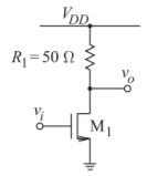
Figure \(\PageIndex{1}\)
- What is IIP3 in terms of voltage?
- What is OIP3 in terms of voltage?
- The distortion properties of the MOSFET circuit below are captured by the nonlinear transconductance equation \(i_{DS1} = 0.02V_{GS1} − 0.5V_{GS1}^{3}\). [You can use interim results from Example 4.4.1.]
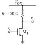
Figure \(\PageIndex{2}\)
- What is IIP3 in terms of voltage?
- What is OIP3 in terms of voltage?
- The distortion properties of the MOSFET circuit below are captured by the nonlinear transconductance equation \(i_{DS2} = b_{1}V_{GS1} + b_{3}V_{GS2}^{3}\), where \(b_{1} = 0.05\text{ A/V}\) and \(b_{3} = −0.2\text{ A/V}^{3}\). [You can use interim results from Example 4.4.1.]
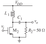
Figure \(\PageIndex{3}\)
- What is the IIP3 in terms of voltage?
- What is the OIP3 in terms of voltage?
- The distortion properties of the MOSFET circuit below are captured by the nonlinear transconductance equation \(i_{DS2} = 0.1V_{GS1} − 0.4V_{GS2}^{3}\). [You can use interim results from Example 4.4.1.]
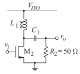
Figure \(\PageIndex{4}\)
- What is the IIP3 in terms of voltage?
- What is the OIP3 in terms of voltage?
- The distortion properties of the MOSFET circuit below are captured by the nonlinear transconductance equations \(i_{DS1} = a_{1}V_{GS1} + a_{3}V_{GS1}^{3}\) and \(i_{DS2} = b_{1}V_{GS1} + b_{3}V_{GS2}^{3}\), where \(a_{1} = 0.01\text{ A/V}\), \(a_{3} = −0.1\text{ A/V}^{3}\), \(b_{1} = 0.05\text{ A/V}\), and \(b_{3} = −0.2\text{ A/V}^{3}\). [You can use interim results from Example 4.4.1.]
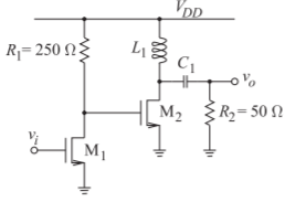
Figure \(\PageIndex{5}\)
- What is the IIP3 in terms of voltage?
- What is the OIP3 in terms of voltage?
4.13.1 Exercises By Section
\(†\)challenging, \(‡\)very challenging
\(§4.2\: 1†\)
\(§4.3\: 2, 3, 4, 5, 6, 7†, 8†, 9†, 10, 11, 12, 13‡\)
\(§4.4\: 14†, 15†, 16†, 17†, 18†, 19†, 20, 21\)
\(§4.5\: 22†, 23†, 24†, 25†, 26†\)
4.13.2 Answers to Selected Exercises
- \(13.75\%\)
- \(0\text{ dB}\)
- (d) \(796\text{ mW}\)
- (d) \(10\text{ kW}\)
- \(180^{\circ}\)
- (d) \(13.98\text{ dB}\)
- (b) \(5V_{\text{IN}}-0.375V_{\text{IN}}^{3}\)
(f) \(17.0\text{ dB}\)
- (f) \(3.8\%\)
- \(4.33\text{ V}\)