
8.7: Cooling and Heating (III)
- Page ID
- 50310
Ground Source (Geothermal) Heat Pumps
Ground-source or geothermal heat pumps (GHPs) are similar to the air-source heat pumps, except that the source of heat is the ground instead of outdoor air.
The following video explains where does the heat in the ground come from.
As you observed in the video, the earth absorbs and stores energy from the sun as heat, resulting in underground temperatures that range between 40 to 80ºF, depending on the location. These temperatures, which are located below the frost line (which is generally 4–5 feet in Pennsylvania), remain constant throughout the year.
The geothermal heat pumps (GHPs) use the earth as a heat sink in the summer and as a heat source in the winter, and therefore rely on the relative warmth of the earth for their heating and cooling production.
Through a system of underground pipes, they transfer heat from the warmer earth to the building in the winter, and take the heat from the building in the summer and discharge it into the cooler ground. Therefore, GHPs do not create heat; they move it from one area to another.
Operating Principle
The GHP system operates much like an air-source or air-to-air heat pump, except that:
- The outside tubing is buried to extract or discharge the heat in the ground;
- The compressor/condenser unit is inside rather than outside the house.
The GHP system also has additional valves to allow heat-exchange fluid (refrigerant) to follow two different paths: one for heating and one for cooling. The GHP takes heat from a warm area and exchanges the heat to a cooler area, and vice versa.
The following video shows how a geothermal heat pump operates.
Classifications of GHPs
Closed-Looped Systems
Horizontal
The horizontal type of installation is generally most cost-effective for residential installations, particularly for new construction where sufficient land is available. It requires trenches at least four feet deep.
Horizontal systems come in two types of layouts, the two pipes method and the slinky method.
Two Pipes
The most common horizontal layouts include:
Two Pipes Layout (Option 1) - One pipe buried at six feet, and another pipe buried at four feet, as shown in Figure 8.7.1.
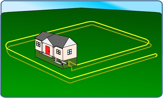
Figure 8.7.1. Horizontal closed-loop system: option 1
Two Pipes Layout (Option 2) - Both pipes placed side-by-side at five feet in the ground in a two-foot wide trench, as shown in Figure 8.7.2.
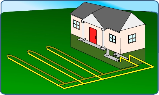
Figure 8.7.2. Horizontal closed-loop system: option 2
The Slinky™ Method
As shown in Figure 8.7.3, the pipe is looped to allow more pipes in a shorter trench, which cuts down on installation costs and makes horizontal installation possible in areas not possible with conventional horizontal applications. Large commercial buildings and schools often use vertical systems because the land area required for horizontal loops would be prohibitive.
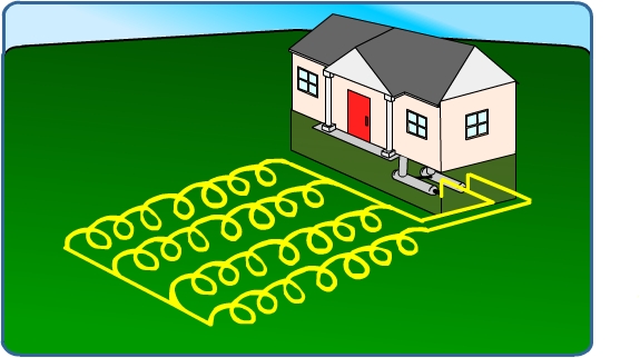
Figure 8.7.3. Horizontal closed-loop system: SlinkyTM Method
Vertical
This type of system may be used when the soil is too shallow for trenching or when one does not want to disturb the existing landscaping.
For a vertical system, holes (approximately four inches in diameter) are drilled about 20 feet apart and 100 to 400 feet deep. Into these holes go two pipes that are connected at the bottom with a U-bend to form a loop. The vertical loops are connected with horizontal pipe (i.e., manifold), placed in trenches, and connected to the heat pump in the building. This is illustrated in Figure 8.7.4.
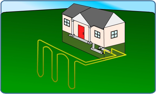
Figure 8.7.4. Vertical closed-loop system
Pond
If a home has source surface water, such as a pond or lake, this type of loop design may be the most economical, since there is no need to dig a trench or a well for the pipes in the ground. In this type of system, the fluid circulates through polyethylene piping in a body of water, just as it does in the ground loops. The pipe may be coiled in a slinky shape to fit more of it into a given amount of space. This loop is recommended only if the water level never drops below six to eight feet at its lowest level, to assure sufficient heat-transfer capability. Pond loops used in a closed system result in no adverse impacts on the aquatic system. This is illustrated in Figure 8.7.5.
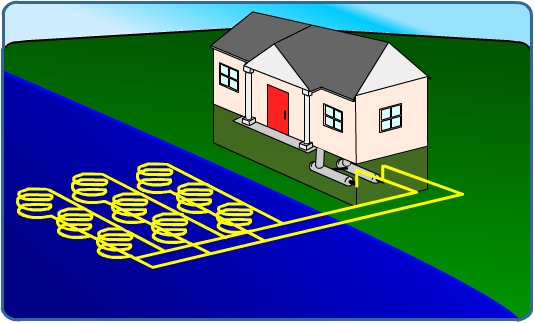
Figure 8.7.5. Closed-loop system: pond
Open-Loop Systems
This type of system uses well(s) or surface body water as the heat exchange fluid that circulates directly through the GHP system, as shown in Figure 8.7.6. Once it has circulated through the system, the water returns to the ground through the well, a recharge well, or a surface discharge. This option is obviously practical only where there is an adequate supply of relatively clean water, and all local codes and regulations regarding groundwater discharge are met.
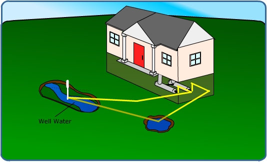
Figure 8.7.6. Open-loop system