
Polymeric Thin Film Dielectrics
- Page ID
- 375
\( \newcommand{\vecs}[1]{\overset { \scriptstyle \rightharpoonup} {\mathbf{#1}} } \)
\( \newcommand{\vecd}[1]{\overset{-\!-\!\rightharpoonup}{\vphantom{a}\smash {#1}}} \)
\( \newcommand{\dsum}{\displaystyle\sum\limits} \)
\( \newcommand{\dint}{\displaystyle\int\limits} \)
\( \newcommand{\dlim}{\displaystyle\lim\limits} \)
\( \newcommand{\id}{\mathrm{id}}\) \( \newcommand{\Span}{\mathrm{span}}\)
( \newcommand{\kernel}{\mathrm{null}\,}\) \( \newcommand{\range}{\mathrm{range}\,}\)
\( \newcommand{\RealPart}{\mathrm{Re}}\) \( \newcommand{\ImaginaryPart}{\mathrm{Im}}\)
\( \newcommand{\Argument}{\mathrm{Arg}}\) \( \newcommand{\norm}[1]{\| #1 \|}\)
\( \newcommand{\inner}[2]{\langle #1, #2 \rangle}\)
\( \newcommand{\Span}{\mathrm{span}}\)
\( \newcommand{\id}{\mathrm{id}}\)
\( \newcommand{\Span}{\mathrm{span}}\)
\( \newcommand{\kernel}{\mathrm{null}\,}\)
\( \newcommand{\range}{\mathrm{range}\,}\)
\( \newcommand{\RealPart}{\mathrm{Re}}\)
\( \newcommand{\ImaginaryPart}{\mathrm{Im}}\)
\( \newcommand{\Argument}{\mathrm{Arg}}\)
\( \newcommand{\norm}[1]{\| #1 \|}\)
\( \newcommand{\inner}[2]{\langle #1, #2 \rangle}\)
\( \newcommand{\Span}{\mathrm{span}}\) \( \newcommand{\AA}{\unicode[.8,0]{x212B}}\)
\( \newcommand{\vectorA}[1]{\vec{#1}} % arrow\)
\( \newcommand{\vectorAt}[1]{\vec{\text{#1}}} % arrow\)
\( \newcommand{\vectorB}[1]{\overset { \scriptstyle \rightharpoonup} {\mathbf{#1}} } \)
\( \newcommand{\vectorC}[1]{\textbf{#1}} \)
\( \newcommand{\vectorD}[1]{\overrightarrow{#1}} \)
\( \newcommand{\vectorDt}[1]{\overrightarrow{\text{#1}}} \)
\( \newcommand{\vectE}[1]{\overset{-\!-\!\rightharpoonup}{\vphantom{a}\smash{\mathbf {#1}}}} \)
\( \newcommand{\vecs}[1]{\overset { \scriptstyle \rightharpoonup} {\mathbf{#1}} } \)
\(\newcommand{\longvect}{\overrightarrow}\)
\( \newcommand{\vecd}[1]{\overset{-\!-\!\rightharpoonup}{\vphantom{a}\smash {#1}}} \)
\(\newcommand{\avec}{\mathbf a}\) \(\newcommand{\bvec}{\mathbf b}\) \(\newcommand{\cvec}{\mathbf c}\) \(\newcommand{\dvec}{\mathbf d}\) \(\newcommand{\dtil}{\widetilde{\mathbf d}}\) \(\newcommand{\evec}{\mathbf e}\) \(\newcommand{\fvec}{\mathbf f}\) \(\newcommand{\nvec}{\mathbf n}\) \(\newcommand{\pvec}{\mathbf p}\) \(\newcommand{\qvec}{\mathbf q}\) \(\newcommand{\svec}{\mathbf s}\) \(\newcommand{\tvec}{\mathbf t}\) \(\newcommand{\uvec}{\mathbf u}\) \(\newcommand{\vvec}{\mathbf v}\) \(\newcommand{\wvec}{\mathbf w}\) \(\newcommand{\xvec}{\mathbf x}\) \(\newcommand{\yvec}{\mathbf y}\) \(\newcommand{\zvec}{\mathbf z}\) \(\newcommand{\rvec}{\mathbf r}\) \(\newcommand{\mvec}{\mathbf m}\) \(\newcommand{\zerovec}{\mathbf 0}\) \(\newcommand{\onevec}{\mathbf 1}\) \(\newcommand{\real}{\mathbb R}\) \(\newcommand{\twovec}[2]{\left[\begin{array}{r}#1 \\ #2 \end{array}\right]}\) \(\newcommand{\ctwovec}[2]{\left[\begin{array}{c}#1 \\ #2 \end{array}\right]}\) \(\newcommand{\threevec}[3]{\left[\begin{array}{r}#1 \\ #2 \\ #3 \end{array}\right]}\) \(\newcommand{\cthreevec}[3]{\left[\begin{array}{c}#1 \\ #2 \\ #3 \end{array}\right]}\) \(\newcommand{\fourvec}[4]{\left[\begin{array}{r}#1 \\ #2 \\ #3 \\ #4 \end{array}\right]}\) \(\newcommand{\cfourvec}[4]{\left[\begin{array}{c}#1 \\ #2 \\ #3 \\ #4 \end{array}\right]}\) \(\newcommand{\fivevec}[5]{\left[\begin{array}{r}#1 \\ #2 \\ #3 \\ #4 \\ #5 \\ \end{array}\right]}\) \(\newcommand{\cfivevec}[5]{\left[\begin{array}{c}#1 \\ #2 \\ #3 \\ #4 \\ #5 \\ \end{array}\right]}\) \(\newcommand{\mattwo}[4]{\left[\begin{array}{rr}#1 \amp #2 \\ #3 \amp #4 \\ \end{array}\right]}\) \(\newcommand{\laspan}[1]{\text{Span}\{#1\}}\) \(\newcommand{\bcal}{\cal B}\) \(\newcommand{\ccal}{\cal C}\) \(\newcommand{\scal}{\cal S}\) \(\newcommand{\wcal}{\cal W}\) \(\newcommand{\ecal}{\cal E}\) \(\newcommand{\coords}[2]{\left\{#1\right\}_{#2}}\) \(\newcommand{\gray}[1]{\color{gray}{#1}}\) \(\newcommand{\lgray}[1]{\color{lightgray}{#1}}\) \(\newcommand{\rank}{\operatorname{rank}}\) \(\newcommand{\row}{\text{Row}}\) \(\newcommand{\col}{\text{Col}}\) \(\renewcommand{\row}{\text{Row}}\) \(\newcommand{\nul}{\text{Nul}}\) \(\newcommand{\var}{\text{Var}}\) \(\newcommand{\corr}{\text{corr}}\) \(\newcommand{\len}[1]{\left|#1\right|}\) \(\newcommand{\bbar}{\overline{\bvec}}\) \(\newcommand{\bhat}{\widehat{\bvec}}\) \(\newcommand{\bperp}{\bvec^\perp}\) \(\newcommand{\xhat}{\widehat{\xvec}}\) \(\newcommand{\vhat}{\widehat{\vvec}}\) \(\newcommand{\uhat}{\widehat{\uvec}}\) \(\newcommand{\what}{\widehat{\wvec}}\) \(\newcommand{\Sighat}{\widehat{\Sigma}}\) \(\newcommand{\lt}{<}\) \(\newcommand{\gt}{>}\) \(\newcommand{\amp}{&}\) \(\definecolor{fillinmathshade}{gray}{0.9}\)The capacitance of a capacitor refers to its ability to store charges. When a piece of dielectric material is inserted between the two plates of a capacitor, its capacitance increases by a factor of \(\epsilon_r\), which is known as the dielectric constant or relative permittivity. When an external electric field is applied to a material, it induces dipole moments that separate the negative charge centers from the positive charge centers in the electrons; this mechanism is known as polarization. The polarization of the dielectric generates an electric field that is in the opposite direction of the external field, contributing to the capacitance increase. The capacitance of a capacitor with dielectric material is governed by
\[C=\dfrac{\epsilon_{0}\epsilon_{r}A} {d}\label{1}\]
where C is the capacitance, \(\epsilon_0\) is the permittivity of the empty space, \(\epsilon_r\) is the relative permittivity, A is the plate area, and d is the separation distance. Besides from increasing capacitance, dielectric materials are also extensively used as insulating media to prevent current flashovers between conductors due to the ionization of air. The application of thin film dielectric materials in sensitive electronic packaging such as multichip modules enables the chips to be packed closer together. As a result, the propagation delay and system cycle time of the chip are reduced. Since many capacitors and electronics are operated at high voltages and under high frequencies, it is important to take the dielectric strength and dielectric loss of a dielectric material into consideration. As the applied voltage increases to a certain extent, it triggers a substantial current flow between the electrodes, leading to the dielectric breakdown. The dielectric strength refers to the maximum filed that can be applied to a material without leading to dielectric breakdown. In a sinusoidally varying field, the thermal agitations due to random jolting from lattice vibration and the strong rotation of molecules together oppose the immediate alignment of the dipoles with the field. As a consequence, dipole moments cannot be induced under high frequencies, leading to dielectric loss. The relative magnitude of energy loss is determined by the loss tangent, as
\[\tan \delta=\dfrac{\epsilon_r''}{\epsilon_r'}\label{2}\]
where \(V_p\) is the real part of the complex dielectric constant and \(\epsilon_r'\) is the imaginary part. Polymeric thin films are widely used in both capacitors and electronic packaging because of their attractive electrical properties, relatively high thermal stability, and ease of processing. Most polymeric dielectric materials have dielectric strength around 100 kV/cm, making them capable for high voltage use. The \(\epsilon_r\) for most polymeric thin films ranges between 2 to 9, which is smaller than that of many ceramic materials but it remains constant over a wide range of frequencies. This poses engineering challenges to increase the capacitance of capacitors, but through space-efficient design, the desired high capacitance can still be reached. For electronic packaging uses, the relatively low \(\epsilon_r\) favors faster signal propagation speed as
\[V_p=\dfrac{c}{\sqrt{\epsilon_r'}}\label{3}\]
where \(V_p\) is signal propagation speed and c is the speed of light. More importantly, polymeric thin films have low loss tangent values, therefore contributing less dielectric loss at high frequencies.
Interaction Mechanism with Electric Field and Dielectric Constant
When an external electric field is applied, it displaces electron and separate them from the charge center, leading to polarization. As mentioned in the introduction, polarization of the dielectric generates an electric field that is in the opposite direction of the external field, which contributes to the capacitance increase. The correlation between the poloarizability and dielectric constant of a material is shown as
\[\epsilon_r=1+\dfrac{N\alpha}{\epsilon_0}\label{4}\]
Where \(\epsilon_r\) is the relative permittivity or dielectric constant, \(\epsilon_o\) is the permittivity of free space, M is molecular weight, \(\alpha\) is the polarizability, N N is the Avogadro constant. The polarizability \(\alpha\) is a proportionality constant that relates the induced dipole moment with the applied field. There are three types of polarization: electronic polarization, atomic polarization, and orientational polarization; they all contribute to the overall dielectric constant depending on the frequency of the applied field. In general, higher polarizability contributes to higher dielectric constants. It is found that the presence of aromatic rings, sulphur, iodine and bromine in a polymer increases its dielectric constant. Specifically, the loose attachment \(\pi\) bond in the aromatic rings makes it easier to be polarized. For iodine and bromine, their large atomic radii allow their electrons to move further from the nucleus. As a result, the electrostatic attraction is reduced; thus easier for polarization. In contrast, elements such as fluorine has small atomic radius and electron cloud are more tightly hold to the nucleus. Thus they have low polarizability and contribute to smaller dielectric constant. Fluorinated polyimides thin films are commonly used in the electronic packaging industry due to their low dielectric constatnts. Fluorinated polyimides include organofluorine components in the form of pendant perfluoroalkyl groups in the monomers and the presence of fluorine contributes to a dielectric constant (lower than 3). Besides from its low polarizability, fluorine also lowers the dielectric constant by increasing the free volume in the polymer. Free volume refers to the volume that is not taken by the polymeric material but occupied by air in the form of pores. Since the relative permittivity of air is about 1, a high proportion of air pores lower the packing density of polarizable group; thus lowers the dielectric constant. The inclusion of pendant groups, bulky groups, and flexible bridging units have similar effect in increasing free volume.
Frequency Dependence and Polymer Chain Polarity
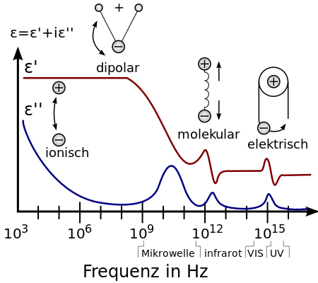
In a sinusoidal filed, polarization oscillate with the changing field. It takes time for dipoles in the material to align. While at low frequencies, dipole alignments can respond fast enough, they do not have sufficient time at very high frequencies. The inability of polarization to respond to the changing field is known as the dielectric loss. Figure 1 illustrates the change in the dielectric constant with the imaginary dielectric loss. It is noticed that there is a dramatic drop in the dielectric constant at frequency approximately beyond 10E9 Hz and the imaginary dielectric loss is at maximum. The maximum dielectric loss suggests that no induced dipole contribute to the dielectric constant as it completely fails to respond to the filed. It is found that the dielectric constants of polar polymers such as PMMA, PVC, Nylon etc. range from 3 to 9 at low frequencies (i.e. 60 Hz) and from 3 to 5 at high frequencies (i.e. 100 Hz). Nonpolar polymers such as PTFE, PE, PP and PS etc., their dielectric constants are not dependent of the frequency as electronic polarization is instantaneous regardless of frequency. Their dielectric constants are always less than 3.
Thermal Stability of Polymer Thin Film
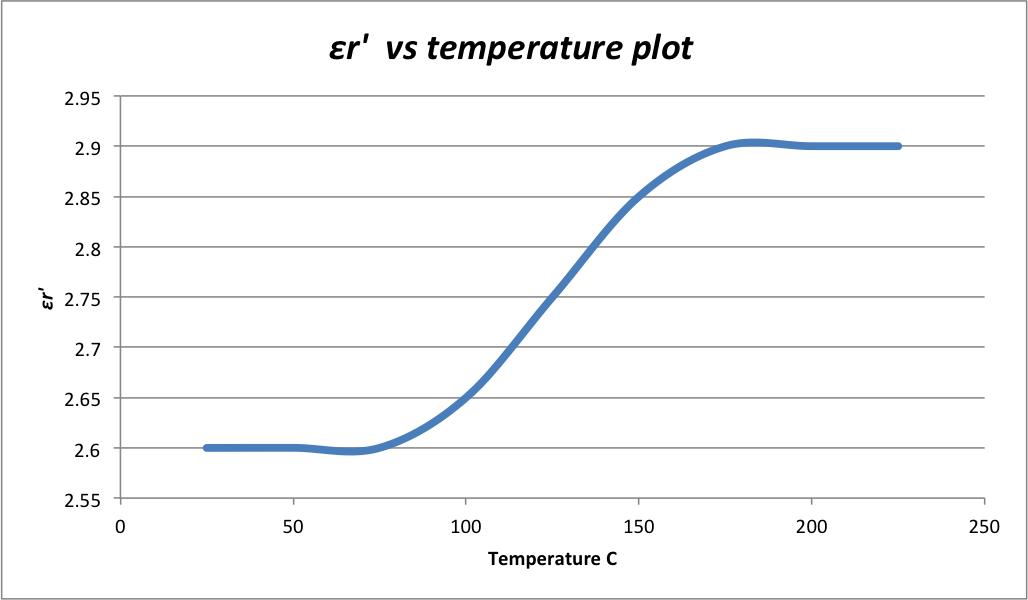
The temperature dependence of the \(\epsilon_r'\) and \(tan\delta\) determines the thermal stability of a polymer dielectric material. Since only electronic polarization takes place in nonpolar polymers, their \(\epsilon_r'\) and \(tan\delta\) remain relatively static, even at elevated temperatures. Therefore, nonpolar polymers such as polypropylene and polystyrene are commonly used in capacitors. The \(\epsilon_r'\) and \(tan\delta\) of polar polymers, on the other hand, shows a great dependency on temperature. Dipoles in the polar polymer chains are randomly orientated in the absence of applied filed and their rotations are restricted by neighboring chains. At low temperature and with electric field applied, the rotations are still largely restricted, leading to limited dipolar contribution to \(\epsilon_r'\). As temperature increases, molecules in the polymer chains become more active and mobile, freeing out some space for dipole rotations. As a result, dipoles can better align with the field. Thus \(\epsilon_r'\) and \(tan\delta\) of polar polymers increase with temperature. Figure 2 schematically demonstrate the correlation of the \(\epsilon_r'\) and temperature of a polar polymer.
Aging Effect of Thin Film Dielectric Material
Insulation aging refers to the deterioration of the insulation properties of a dielectric material throughout time. Aging takes place at anytime even without the presence of an electric field. There are many factors contribute either directly or indirectly to the aging effect. For instance, elevated temperature and mechanical stress can lead to structural defects in the dielectric material, thereby decreasing its dielectric strength. Serve ambient working condition such as high humidity also degrade the chemical structure and electric property of a material through various chemical processes. For instance, the moisture absorption of conventional polyimide thin film causes swelling in the polyimide layer and a significant increase in its dielectric constant. Polymeric dielectric materials are also vulnerable to oxidation as oxygen attacks and cleave the C-C bonds in the polymer. The addition of anti-oxidants to the polymer alleviates the oxidation effect and increase the thermal stability of the material.
Dielectric Deposition Techniques of Polymers
-Spin Coating
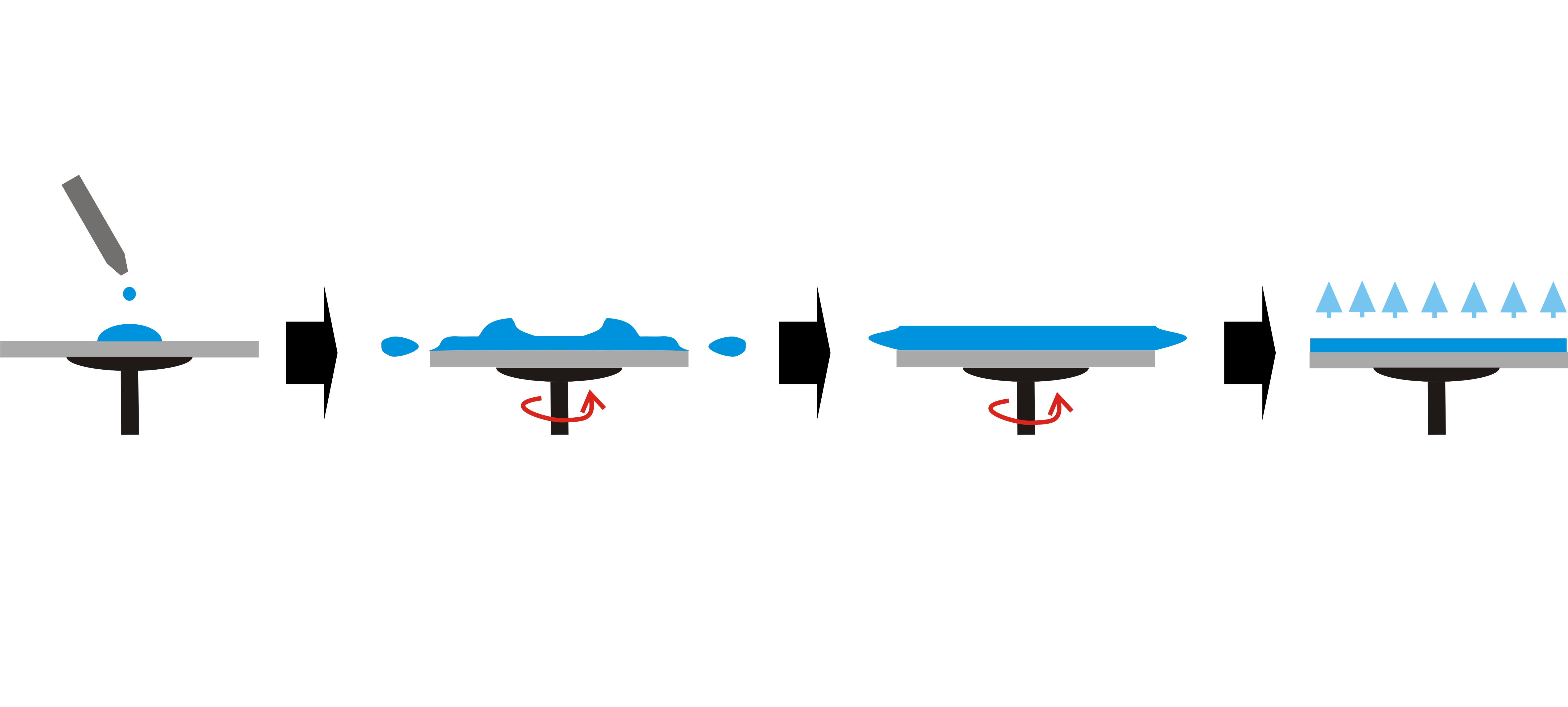
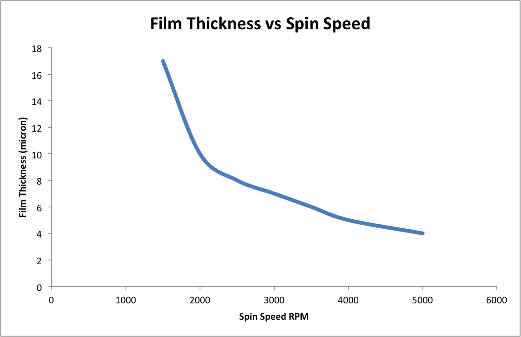
A controlled amount of polymer solution is first dispensed onto the substrate surface. On a vacuum chuck that spins at a high speed (i.e. 5000 rpm), the polymer solution is distributed across the surface of the substrate. Figure 3 schematically shows the spin coating technique. The proportion of solids and solvent in the polymer solution as well as the spin speed, determine the thickness of the deposition. Figure 4 schematically illustrates the correlation between the film thickness and the spin speed. Spin coating generates evenly distributed polymer layers on the substrate, which ensures consistent electrical properties across the entire substrate. However, this technique is costly due to a considerable amount of material waste during spinning. Also edge beads tend to form during the spinning, requiring extra steps for removal.
-Extrusion Coating
In extrusion coating, the polyimide solution is extruded onto a moving substrate through an extrusion head that is positioned at a set height above the substrate surface. A precision linear orifice in the extrusion head precisely controls the amount of the solution being extruded. Compared to spin coating, extrusion is less costly due to less material waste. This makes it ideal for coating on large area substrates. The extrusion coating also yields excellent uniformities in film thicknesses. Commercially, extrusion coating technique is widely on microelectronic fabrication lines.
Questions
- The relative permittivity \(\epsilon_r\)of most polymeric thin films ranges between 2 to 9, which is smaller than that of many ceramic materials. What are the TWO main reasons to use polymeric thin films in wide-frequency-range capacitors?
- Given that the real relative permittivity of a thin film dielectric material used in a chip is 3.5, what is the signal propagation speed?
- If you were an engineer working for a chip fabrication factory, would you recommend the spin coating technique to your manager? Why?
Answers
- i. The relative permittivity \(\epsilon_r\) of most polymeric thin films remains constant over a wider range of frequencies.
ii. Polymeric thin films have low loss tangent values, therefore contributing less dielectric loss at high frequencies.
- Using eqn 3, plugging in the speed of light and \(\epsilon_r'\)=3.5. Answer:1.6E8 m/s
- I would not recommend spin coating. Spin coating is not suitable for high throughout production such as the fabrication line. Also spin coat can be costly due to a large amount of material waste. Instead, I would recommend extrusion coating.
Reference
- L. Solymar and D. Walsh, Electrical Properties Of Materials, 7th ed. Oxford University Press, 2014.
- S. Kasap, Principles of electronic materials and devices. Boston: McGraw-Hill, 2006.
- J. Webster, 'Thin Film Polymer Dielectrics for High-Voltage Applications under Severe Environments', Master of Science, Virginia Polytechnic Institute and State University, 1998.
- Z. Ahmad, Polymeric Dielectric Mateirals, 1st ed. .
Contributors and Attributions
- Junru Chen (B.S. University of California, Davis)