Polarization of Waves
- Page ID
- 345
\( \newcommand{\vecs}[1]{\overset { \scriptstyle \rightharpoonup} {\mathbf{#1}} } \)
\( \newcommand{\vecd}[1]{\overset{-\!-\!\rightharpoonup}{\vphantom{a}\smash {#1}}} \)
\( \newcommand{\dsum}{\displaystyle\sum\limits} \)
\( \newcommand{\dint}{\displaystyle\int\limits} \)
\( \newcommand{\dlim}{\displaystyle\lim\limits} \)
\( \newcommand{\id}{\mathrm{id}}\) \( \newcommand{\Span}{\mathrm{span}}\)
( \newcommand{\kernel}{\mathrm{null}\,}\) \( \newcommand{\range}{\mathrm{range}\,}\)
\( \newcommand{\RealPart}{\mathrm{Re}}\) \( \newcommand{\ImaginaryPart}{\mathrm{Im}}\)
\( \newcommand{\Argument}{\mathrm{Arg}}\) \( \newcommand{\norm}[1]{\| #1 \|}\)
\( \newcommand{\inner}[2]{\langle #1, #2 \rangle}\)
\( \newcommand{\Span}{\mathrm{span}}\)
\( \newcommand{\id}{\mathrm{id}}\)
\( \newcommand{\Span}{\mathrm{span}}\)
\( \newcommand{\kernel}{\mathrm{null}\,}\)
\( \newcommand{\range}{\mathrm{range}\,}\)
\( \newcommand{\RealPart}{\mathrm{Re}}\)
\( \newcommand{\ImaginaryPart}{\mathrm{Im}}\)
\( \newcommand{\Argument}{\mathrm{Arg}}\)
\( \newcommand{\norm}[1]{\| #1 \|}\)
\( \newcommand{\inner}[2]{\langle #1, #2 \rangle}\)
\( \newcommand{\Span}{\mathrm{span}}\) \( \newcommand{\AA}{\unicode[.8,0]{x212B}}\)
\( \newcommand{\vectorA}[1]{\vec{#1}} % arrow\)
\( \newcommand{\vectorAt}[1]{\vec{\text{#1}}} % arrow\)
\( \newcommand{\vectorB}[1]{\overset { \scriptstyle \rightharpoonup} {\mathbf{#1}} } \)
\( \newcommand{\vectorC}[1]{\textbf{#1}} \)
\( \newcommand{\vectorD}[1]{\overrightarrow{#1}} \)
\( \newcommand{\vectorDt}[1]{\overrightarrow{\text{#1}}} \)
\( \newcommand{\vectE}[1]{\overset{-\!-\!\rightharpoonup}{\vphantom{a}\smash{\mathbf {#1}}}} \)
\( \newcommand{\vecs}[1]{\overset { \scriptstyle \rightharpoonup} {\mathbf{#1}} } \)
\(\newcommand{\longvect}{\overrightarrow}\)
\( \newcommand{\vecd}[1]{\overset{-\!-\!\rightharpoonup}{\vphantom{a}\smash {#1}}} \)
\(\newcommand{\avec}{\mathbf a}\) \(\newcommand{\bvec}{\mathbf b}\) \(\newcommand{\cvec}{\mathbf c}\) \(\newcommand{\dvec}{\mathbf d}\) \(\newcommand{\dtil}{\widetilde{\mathbf d}}\) \(\newcommand{\evec}{\mathbf e}\) \(\newcommand{\fvec}{\mathbf f}\) \(\newcommand{\nvec}{\mathbf n}\) \(\newcommand{\pvec}{\mathbf p}\) \(\newcommand{\qvec}{\mathbf q}\) \(\newcommand{\svec}{\mathbf s}\) \(\newcommand{\tvec}{\mathbf t}\) \(\newcommand{\uvec}{\mathbf u}\) \(\newcommand{\vvec}{\mathbf v}\) \(\newcommand{\wvec}{\mathbf w}\) \(\newcommand{\xvec}{\mathbf x}\) \(\newcommand{\yvec}{\mathbf y}\) \(\newcommand{\zvec}{\mathbf z}\) \(\newcommand{\rvec}{\mathbf r}\) \(\newcommand{\mvec}{\mathbf m}\) \(\newcommand{\zerovec}{\mathbf 0}\) \(\newcommand{\onevec}{\mathbf 1}\) \(\newcommand{\real}{\mathbb R}\) \(\newcommand{\twovec}[2]{\left[\begin{array}{r}#1 \\ #2 \end{array}\right]}\) \(\newcommand{\ctwovec}[2]{\left[\begin{array}{c}#1 \\ #2 \end{array}\right]}\) \(\newcommand{\threevec}[3]{\left[\begin{array}{r}#1 \\ #2 \\ #3 \end{array}\right]}\) \(\newcommand{\cthreevec}[3]{\left[\begin{array}{c}#1 \\ #2 \\ #3 \end{array}\right]}\) \(\newcommand{\fourvec}[4]{\left[\begin{array}{r}#1 \\ #2 \\ #3 \\ #4 \end{array}\right]}\) \(\newcommand{\cfourvec}[4]{\left[\begin{array}{c}#1 \\ #2 \\ #3 \\ #4 \end{array}\right]}\) \(\newcommand{\fivevec}[5]{\left[\begin{array}{r}#1 \\ #2 \\ #3 \\ #4 \\ #5 \\ \end{array}\right]}\) \(\newcommand{\cfivevec}[5]{\left[\begin{array}{c}#1 \\ #2 \\ #3 \\ #4 \\ #5 \\ \end{array}\right]}\) \(\newcommand{\mattwo}[4]{\left[\begin{array}{rr}#1 \amp #2 \\ #3 \amp #4 \\ \end{array}\right]}\) \(\newcommand{\laspan}[1]{\text{Span}\{#1\}}\) \(\newcommand{\bcal}{\cal B}\) \(\newcommand{\ccal}{\cal C}\) \(\newcommand{\scal}{\cal S}\) \(\newcommand{\wcal}{\cal W}\) \(\newcommand{\ecal}{\cal E}\) \(\newcommand{\coords}[2]{\left\{#1\right\}_{#2}}\) \(\newcommand{\gray}[1]{\color{gray}{#1}}\) \(\newcommand{\lgray}[1]{\color{lightgray}{#1}}\) \(\newcommand{\rank}{\operatorname{rank}}\) \(\newcommand{\row}{\text{Row}}\) \(\newcommand{\col}{\text{Col}}\) \(\renewcommand{\row}{\text{Row}}\) \(\newcommand{\nul}{\text{Nul}}\) \(\newcommand{\var}{\text{Var}}\) \(\newcommand{\corr}{\text{corr}}\) \(\newcommand{\len}[1]{\left|#1\right|}\) \(\newcommand{\bbar}{\overline{\bvec}}\) \(\newcommand{\bhat}{\widehat{\bvec}}\) \(\newcommand{\bperp}{\bvec^\perp}\) \(\newcommand{\xhat}{\widehat{\xvec}}\) \(\newcommand{\vhat}{\widehat{\vvec}}\) \(\newcommand{\uhat}{\widehat{\uvec}}\) \(\newcommand{\what}{\widehat{\wvec}}\) \(\newcommand{\Sighat}{\widehat{\Sigma}}\) \(\newcommand{\lt}{<}\) \(\newcommand{\gt}{>}\) \(\newcommand{\amp}{&}\) \(\definecolor{fillinmathshade}{gray}{0.9}\)The electromagnetic waves such as visible light and microwaves consist of orthogonal electric and magnetic field both orthogonal to the propagation direction of the wave. The polarization of the electromagnetic wave is meant to describe the magnitude and the direction of the electric field of the wave. Specifically, the polarization of a radiated wave is defined as "that property of a radiated electromagnetic wave describing the time-varying direction and relative magnitude of the electric field vector; the trace and magnitude of the electric field vector are observed in the direction of light propagation"1,2,
Introduction
The polarization of electromagnetic wave (EMW) is the basic property of the EMW, which is widely used and controlled in Laser3,4, interferometer5,6 and photography7. The sketch for the linear polarization (red curves) of EMW is shown in Fig.1 below.
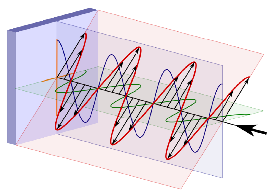
based on the Maxwell equations9 for EMW, the electric field can be split into orthogonal x-component Exand y-component Ey10 :
where Ex is the magnitude of the electric field in x-direction, Ey is the magnitude of the electric field in x-direction, Phix is the phase of the electric field in x-direction, Phiy is the phase of the electric field in y-direction and omega is the frequency of the EMW. The three major polarization state are defined based on the differences in phase and magnitude of x-direction and y-direction EMW.
Linear Polarization
Assume Ey in the mathematical expression for the electric field equals to zero, which gives the definition of electric field as:
The electric field on certain propagation position will oscillate only on the x-axis with the angular frequency of omega, which is shown as below:
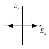
Fig.2 x-axis linear polarization12
Thus, the similar polarization of electric field on only a specific straight direction is defined as linear polarization. On the other hand, Assume Ey equals to zero, which gives the electric field as:
The electric field only oscillate on the y-axis with the angular frequency of omega, which is shown in Fig.3:
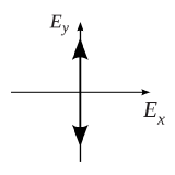
Fig. 3 y-axis linear polarization13
Generally, with x-direction oscillation and y-direction oscillation share the same phase, the linear polarization field pattern can be express as:
the angle of the linear oscillation towards the x-axis is calculated as:
The polarization sketch is shown in Fig. 4:
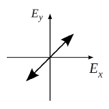
Fig. 4 general linear polarization14
Circular Polarization
The circular polarization state is a special polarization state of elliptical polarization state, which satisfies the following conditions: 1) The field must have two orthogonal polarized components (such as x-direction and y-direction). 2) The two components mist have the same magnitude (Ex = Ey), 3) The two components must have a time-phase difference of multiples of 90 degrees. Thus the field pattern can be written as:
And the polarization pattern can be drawn as Fig.4 and Fig.5:
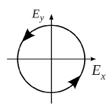
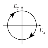
Fig.5 left circular polarization15 Fig.6 right circular polarization16
the left circular polarization (counterclockwise) is achieved when number n equals to (4m-1) (m is integer) and the right circular polarization (clockwise) is achieved when number n equals to (4m+1).
Elliptical Polarization
The elliptical polarization is the general definition of the EMW polarization state whose field pattern can be expressed after make the simple math transformation of Ex and Ey:
where :
thus the electric field pattern can be calculated as :
The above is a elliptical polarization which can be seen as the superposition of two circular polarization possessing different magnitude and direction. And the general elliptical polarization pattern is shown below:
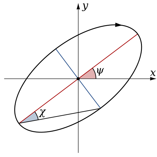
Fig. 7 general elliptical polarization pattern 11
the major and minor axis slope (psi) is calculated by the phase difference between x-component and y-component.
Questions
1. What is the polarization of the natural light and why?
2. What's the relationship between these polarization and how can we control?
3. How can we define the rotation direction of elliptical polarization?
Answers
1. What is the polarization of the natural light and why?
The cause of the light polarization is the vibration direction of the lighting material. The natural light comes from the molecular vibration of the nuclear fusion in Sun and this vibration is homogeneous on all directions. Thus the natural light does not have a specific polarization or can be defined as non-polarized EMW.
2. What's the relationship between these polarization and how can we control?
The circular polarization can be seen as the superposition of two linear polarization waves having the same magnitude, orthogonal polarization direction and pi/2 phase difference. The elliptical polarization wave can be seen as the superposition of two linear polarization waves having the different magnitude, orthogonal polarization state and the stable phase difference. Above all, the linear polarization state and circular polarization state are only the special states of elliptical polarization state.
3. How can we define the rotation direction of elliptical polarization?
the circular and elliptical polarization state can be formed by letting linear polarization wave pass through a quarter wave plate at the specific angle. And the linear polarization state can be formed by the linear polarization plate as well as the polarization rotator.
References
- Balanis C A. Antenna theory: analysis and design[M]. John Wiley & Sons, 2012.
- "IEEE Standard 145-1983, IEEE Standard Definitions of Terms for Antennas," reprinted in IEEE Trans, Antennas Propagat., vol. AP-31, no.6, part II, pp 1-29, November 1983.
- Ehrlich D J, Tsao J Y. A review of laser–microchemical processing[J]. Journal of Vacuum Science & Technology B, 1983, 1(4): 969-984.
- Bridge N J, Buckingham A D. The polarization of laser light scattered by gases[J]. Proceedings of the Royal Society of London. Series A. Mathematical and Physical Sciences, 1966, 295(1442): 334-349.
- Michelson A A, Pease F G. Measurement of the diameter of Alpha-Orionis by the interferometer[J]. Proceedings of the National Academy of Sciences of the United States of America, 1921, 7(5): 143.
- Wang Y J, Anderson D Z, Bright V M, et al. Atom Michelson interferometer on a chip using a Bose-Einstein condensate[J]. Physical review letters, 2005, 94(9): 090405.
- On Photography
- Linear polarized light entering quarter plate
- Maxwell J C. A treatise on electricity and magnetism[M]. Clarendon press, 1881.
- Balanis C A. Advanced engineering electromagnetics[M]. Page. 154-172, New York: Wiley, 1989.
- Taken with permission from Wikipedia
Contributors and Attributions
- Guangyao Liu, ECE, University of California, Davis

