
2.8: Optical anisotropy and the optical indicatrix
- Page ID
- 8312
")
\( \newcommand{\vecs}[1]{\overset { \scriptstyle \rightharpoonup} {\mathbf{#1}} } \)
\( \newcommand{\vecd}[1]{\overset{-\!-\!\rightharpoonup}{\vphantom{a}\smash {#1}}} \)
\( \newcommand{\id}{\mathrm{id}}\) \( \newcommand{\Span}{\mathrm{span}}\)
( \newcommand{\kernel}{\mathrm{null}\,}\) \( \newcommand{\range}{\mathrm{range}\,}\)
\( \newcommand{\RealPart}{\mathrm{Re}}\) \( \newcommand{\ImaginaryPart}{\mathrm{Im}}\)
\( \newcommand{\Argument}{\mathrm{Arg}}\) \( \newcommand{\norm}[1]{\| #1 \|}\)
\( \newcommand{\inner}[2]{\langle #1, #2 \rangle}\)
\( \newcommand{\Span}{\mathrm{span}}\)
\( \newcommand{\id}{\mathrm{id}}\)
\( \newcommand{\Span}{\mathrm{span}}\)
\( \newcommand{\kernel}{\mathrm{null}\,}\)
\( \newcommand{\range}{\mathrm{range}\,}\)
\( \newcommand{\RealPart}{\mathrm{Re}}\)
\( \newcommand{\ImaginaryPart}{\mathrm{Im}}\)
\( \newcommand{\Argument}{\mathrm{Arg}}\)
\( \newcommand{\norm}[1]{\| #1 \|}\)
\( \newcommand{\inner}[2]{\langle #1, #2 \rangle}\)
\( \newcommand{\Span}{\mathrm{span}}\) \( \newcommand{\AA}{\unicode[.8,0]{x212B}}\)
\( \newcommand{\vectorA}[1]{\vec{#1}} % arrow\)
\( \newcommand{\vectorAt}[1]{\vec{\text{#1}}} % arrow\)
\( \newcommand{\vectorB}[1]{\overset { \scriptstyle \rightharpoonup} {\mathbf{#1}} } \)
\( \newcommand{\vectorC}[1]{\textbf{#1}} \)
\( \newcommand{\vectorD}[1]{\overrightarrow{#1}} \)
\( \newcommand{\vectorDt}[1]{\overrightarrow{\text{#1}}} \)
\( \newcommand{\vectE}[1]{\overset{-\!-\!\rightharpoonup}{\vphantom{a}\smash{\mathbf {#1}}}} \)
\( \newcommand{\vecs}[1]{\overset { \scriptstyle \rightharpoonup} {\mathbf{#1}} } \)
\( \newcommand{\vecd}[1]{\overset{-\!-\!\rightharpoonup}{\vphantom{a}\smash {#1}}} \)
\(\newcommand{\avec}{\mathbf a}\) \(\newcommand{\bvec}{\mathbf b}\) \(\newcommand{\cvec}{\mathbf c}\) \(\newcommand{\dvec}{\mathbf d}\) \(\newcommand{\dtil}{\widetilde{\mathbf d}}\) \(\newcommand{\evec}{\mathbf e}\) \(\newcommand{\fvec}{\mathbf f}\) \(\newcommand{\nvec}{\mathbf n}\) \(\newcommand{\pvec}{\mathbf p}\) \(\newcommand{\qvec}{\mathbf q}\) \(\newcommand{\svec}{\mathbf s}\) \(\newcommand{\tvec}{\mathbf t}\) \(\newcommand{\uvec}{\mathbf u}\) \(\newcommand{\vvec}{\mathbf v}\) \(\newcommand{\wvec}{\mathbf w}\) \(\newcommand{\xvec}{\mathbf x}\) \(\newcommand{\yvec}{\mathbf y}\) \(\newcommand{\zvec}{\mathbf z}\) \(\newcommand{\rvec}{\mathbf r}\) \(\newcommand{\mvec}{\mathbf m}\) \(\newcommand{\zerovec}{\mathbf 0}\) \(\newcommand{\onevec}{\mathbf 1}\) \(\newcommand{\real}{\mathbb R}\) \(\newcommand{\twovec}[2]{\left[\begin{array}{r}#1 \\ #2 \end{array}\right]}\) \(\newcommand{\ctwovec}[2]{\left[\begin{array}{c}#1 \\ #2 \end{array}\right]}\) \(\newcommand{\threevec}[3]{\left[\begin{array}{r}#1 \\ #2 \\ #3 \end{array}\right]}\) \(\newcommand{\cthreevec}[3]{\left[\begin{array}{c}#1 \\ #2 \\ #3 \end{array}\right]}\) \(\newcommand{\fourvec}[4]{\left[\begin{array}{r}#1 \\ #2 \\ #3 \\ #4 \end{array}\right]}\) \(\newcommand{\cfourvec}[4]{\left[\begin{array}{c}#1 \\ #2 \\ #3 \\ #4 \end{array}\right]}\) \(\newcommand{\fivevec}[5]{\left[\begin{array}{r}#1 \\ #2 \\ #3 \\ #4 \\ #5 \\ \end{array}\right]}\) \(\newcommand{\cfivevec}[5]{\left[\begin{array}{c}#1 \\ #2 \\ #3 \\ #4 \\ #5 \\ \end{array}\right]}\) \(\newcommand{\mattwo}[4]{\left[\begin{array}{rr}#1 \amp #2 \\ #3 \amp #4 \\ \end{array}\right]}\) \(\newcommand{\laspan}[1]{\text{Span}\{#1\}}\) \(\newcommand{\bcal}{\cal B}\) \(\newcommand{\ccal}{\cal C}\) \(\newcommand{\scal}{\cal S}\) \(\newcommand{\wcal}{\cal W}\) \(\newcommand{\ecal}{\cal E}\) \(\newcommand{\coords}[2]{\left\{#1\right\}_{#2}}\) \(\newcommand{\gray}[1]{\color{gray}{#1}}\) \(\newcommand{\lgray}[1]{\color{lightgray}{#1}}\) \(\newcommand{\rank}{\operatorname{rank}}\) \(\newcommand{\row}{\text{Row}}\) \(\newcommand{\col}{\text{Col}}\) \(\renewcommand{\row}{\text{Row}}\) \(\newcommand{\nul}{\text{Nul}}\) \(\newcommand{\var}{\text{Var}}\) \(\newcommand{\corr}{\text{corr}}\) \(\newcommand{\len}[1]{\left|#1\right|}\) \(\newcommand{\bbar}{\overline{\bvec}}\) \(\newcommand{\bhat}{\widehat{\bvec}}\) \(\newcommand{\bperp}{\bvec^\perp}\) \(\newcommand{\xhat}{\widehat{\xvec}}\) \(\newcommand{\vhat}{\widehat{\vvec}}\) \(\newcommand{\uhat}{\widehat{\uvec}}\) \(\newcommand{\what}{\widehat{\wvec}}\) \(\newcommand{\Sighat}{\widehat{\Sigma}}\) \(\newcommand{\lt}{<}\) \(\newcommand{\gt}{>}\) \(\newcommand{\amp}{&}\) \(\definecolor{fillinmathshade}{gray}{0.9}\)In transparent materials with anisotropic dielectric permittivity, important optical effects can be observed. Recall that a light wave may be considered in terms of oscillating transverse electric and magnetic fields. Here we concentrate on the effects of the electric field. When discussing optical properties it is important to remember that this field is in a direction lying in the wavefront. It is not necessarily perpendicular to the direction of propagation. The interaction between the electric field and the material is governed by the dielectric permittivity discussed in the previous section. A large value of the permittivity gives rise to a large refractive index, and consequently the wave travels relatively slowly. (The refractive index n is related to the velocity of light in the medium, v, and the velocity in a vacuum, c, by n = c/v.)
In an anisotropic material the refractive indices can again be illustrated by a representation surface - the optical indicatrix. For each (orthogonal) principal direction in the anisotropic material, there is an associated principal refractive index. The variation of the refractive index with the plane of the wavefront can be represented by an ellipsoid. The semi-axes of this optical indicatrix are directly proportional to the principal refractive indices.
Optically isotropic materials (e.g. cubic crystals) have one refractive index, with a spherical indicatrix.
Crystals with one 3, 4 or 6 fold axis of symmetry have a principal axis of the ellipsoid along this symmetry axis. These uniaxial crystals have an indicatrix which is an ellipsoid with a circular cross-section perpendicular to the major symmetry axis – an ellipsoid of revolution. They have two principal refractive indices and one optic axis (parallel to the symmetry axis and so perpendicular to the circular section).
In general, the electric field of a light wave experiences two permitted vibration directions, known as the fast and slow directions, both in the plane of the wavefront, and determined by the shape of the indicatrix. Consider a section passing through the origin of the indicatrix for a uniaxial crystal, and orientated parallel to the wavefronts, as shown by the dotted line in the left-hand figure below. The two permitted vibration directions are given by the major and minor axes of this section. The corresponding refractive indices are the lengths of these axes. The section will be elliptical unless the light is travelling along the optic axis so that the plane of the wavefront coincides with the circular section of the ellipsoid.
The observation of two refractive indices for a general orientation of the wavefront is known as birefringence. Related effects such as stress-induced birefringence and photoelasticity are discussed in the Photoelasticity TLP.
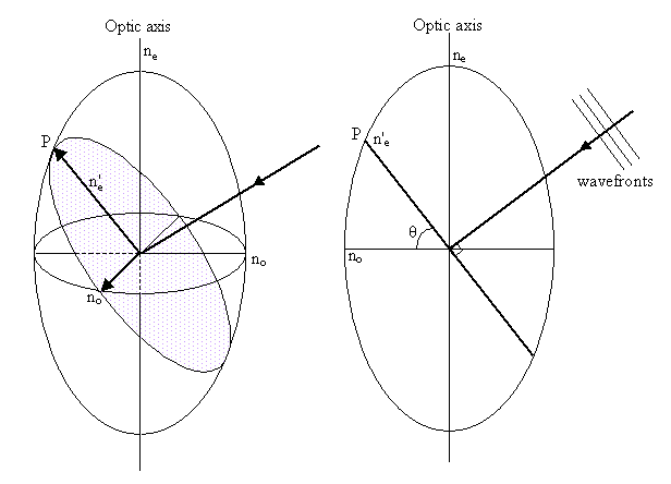
The ordinary vibration direction lies in the circular section of the indicatrix (i.e. perpendicular to the optic axis) with refractive index no. Light travelling along the optic axis experiences just this refractive index - the ordinary refractive index.
The extraordinary vibration direction lies in the plane of the wavefront and perpendicular to the ordinary vibration direction, and has refractive index n'e. The value of n'e is determined from the ordinary refractive index and the principal extraordinary refractive index ne, as follows.
Consider a cross-section of the indicatrix (as shown in the diagram on the right above), containing the optic axis and the extraordinary vibration direction. The equation for this ellipse will be:
\[\frac{x^{2}}{n_{o}^{2}}+\frac{z^{2}}{n_{e}^{2}}=1\]
For the point P, x = ne'cosθ, and y = ne'sinθ. Therefore
\[\frac{\left(n_{e}^{\prime} \cos \theta\right)^{2}}{n_{o}^{2}}+\frac{\left(n_{e}^{\prime} \sin \theta\right)^{2}}{n_{e}^{2}}=1\]
For a general extraordinary wave, the direction in which the light energy travels, the ray direction, is no longer perpendicular to the wavefront. For an explanation see, for example, the link to Optical Birefringence in Going further.
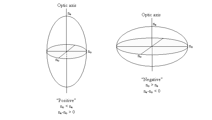
As a side note, the relative magnitudes of no and ne determine whether a material is defined as optically positive or negative, the optical sign.
Example: calcite rhomb
The birefringence (defined as \(\left|n_{0}-n_{e}\right|\)) in calcite is so large that two images can easily be observed when viewing an object through a suitable crystal with the naked eye. One of which is due to the ordinary wave (with electric field vibrating parallel to the ordinary vibration direction) and the other is due to the extraordinary wave (with electric field vibrating parallel to the extraordinary vibration direction).
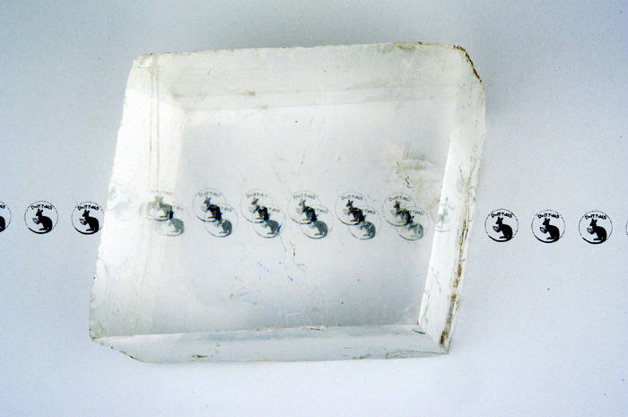
The DoITPoMS logo viewed through a calcite rhomb (click on image to view larger version)
In calcite, the planar carbonate groups all lie in planes normal to the three-fold axis - the optic axis. The groups are well separated in the direction of the axis. This makes the crystal less polarisable parallel to the axis, so the refractive index for vibrations parallel to the triad axis is smaller than for vibrations perpendicular to it (making the crystal optically negative: ne < no).
https://www.doitpoms.ac.uk/tlplib/an...os/Calcite.mp4
(Video of calcite structure)