
5.9: Indentation Plastometry
- Page ID
- 35629
")
\( \newcommand{\vecs}[1]{\overset { \scriptstyle \rightharpoonup} {\mathbf{#1}} } \)
\( \newcommand{\vecd}[1]{\overset{-\!-\!\rightharpoonup}{\vphantom{a}\smash {#1}}} \)
\( \newcommand{\dsum}{\displaystyle\sum\limits} \)
\( \newcommand{\dint}{\displaystyle\int\limits} \)
\( \newcommand{\dlim}{\displaystyle\lim\limits} \)
\( \newcommand{\id}{\mathrm{id}}\) \( \newcommand{\Span}{\mathrm{span}}\)
( \newcommand{\kernel}{\mathrm{null}\,}\) \( \newcommand{\range}{\mathrm{range}\,}\)
\( \newcommand{\RealPart}{\mathrm{Re}}\) \( \newcommand{\ImaginaryPart}{\mathrm{Im}}\)
\( \newcommand{\Argument}{\mathrm{Arg}}\) \( \newcommand{\norm}[1]{\| #1 \|}\)
\( \newcommand{\inner}[2]{\langle #1, #2 \rangle}\)
\( \newcommand{\Span}{\mathrm{span}}\)
\( \newcommand{\id}{\mathrm{id}}\)
\( \newcommand{\Span}{\mathrm{span}}\)
\( \newcommand{\kernel}{\mathrm{null}\,}\)
\( \newcommand{\range}{\mathrm{range}\,}\)
\( \newcommand{\RealPart}{\mathrm{Re}}\)
\( \newcommand{\ImaginaryPart}{\mathrm{Im}}\)
\( \newcommand{\Argument}{\mathrm{Arg}}\)
\( \newcommand{\norm}[1]{\| #1 \|}\)
\( \newcommand{\inner}[2]{\langle #1, #2 \rangle}\)
\( \newcommand{\Span}{\mathrm{span}}\) \( \newcommand{\AA}{\unicode[.8,0]{x212B}}\)
\( \newcommand{\vectorA}[1]{\vec{#1}} % arrow\)
\( \newcommand{\vectorAt}[1]{\vec{\text{#1}}} % arrow\)
\( \newcommand{\vectorB}[1]{\overset { \scriptstyle \rightharpoonup} {\mathbf{#1}} } \)
\( \newcommand{\vectorC}[1]{\textbf{#1}} \)
\( \newcommand{\vectorD}[1]{\overrightarrow{#1}} \)
\( \newcommand{\vectorDt}[1]{\overrightarrow{\text{#1}}} \)
\( \newcommand{\vectE}[1]{\overset{-\!-\!\rightharpoonup}{\vphantom{a}\smash{\mathbf {#1}}}} \)
\( \newcommand{\vecs}[1]{\overset { \scriptstyle \rightharpoonup} {\mathbf{#1}} } \)
\(\newcommand{\longvect}{\overrightarrow}\)
\( \newcommand{\vecd}[1]{\overset{-\!-\!\rightharpoonup}{\vphantom{a}\smash {#1}}} \)
\(\newcommand{\avec}{\mathbf a}\) \(\newcommand{\bvec}{\mathbf b}\) \(\newcommand{\cvec}{\mathbf c}\) \(\newcommand{\dvec}{\mathbf d}\) \(\newcommand{\dtil}{\widetilde{\mathbf d}}\) \(\newcommand{\evec}{\mathbf e}\) \(\newcommand{\fvec}{\mathbf f}\) \(\newcommand{\nvec}{\mathbf n}\) \(\newcommand{\pvec}{\mathbf p}\) \(\newcommand{\qvec}{\mathbf q}\) \(\newcommand{\svec}{\mathbf s}\) \(\newcommand{\tvec}{\mathbf t}\) \(\newcommand{\uvec}{\mathbf u}\) \(\newcommand{\vvec}{\mathbf v}\) \(\newcommand{\wvec}{\mathbf w}\) \(\newcommand{\xvec}{\mathbf x}\) \(\newcommand{\yvec}{\mathbf y}\) \(\newcommand{\zvec}{\mathbf z}\) \(\newcommand{\rvec}{\mathbf r}\) \(\newcommand{\mvec}{\mathbf m}\) \(\newcommand{\zerovec}{\mathbf 0}\) \(\newcommand{\onevec}{\mathbf 1}\) \(\newcommand{\real}{\mathbb R}\) \(\newcommand{\twovec}[2]{\left[\begin{array}{r}#1 \\ #2 \end{array}\right]}\) \(\newcommand{\ctwovec}[2]{\left[\begin{array}{c}#1 \\ #2 \end{array}\right]}\) \(\newcommand{\threevec}[3]{\left[\begin{array}{r}#1 \\ #2 \\ #3 \end{array}\right]}\) \(\newcommand{\cthreevec}[3]{\left[\begin{array}{c}#1 \\ #2 \\ #3 \end{array}\right]}\) \(\newcommand{\fourvec}[4]{\left[\begin{array}{r}#1 \\ #2 \\ #3 \\ #4 \end{array}\right]}\) \(\newcommand{\cfourvec}[4]{\left[\begin{array}{c}#1 \\ #2 \\ #3 \\ #4 \end{array}\right]}\) \(\newcommand{\fivevec}[5]{\left[\begin{array}{r}#1 \\ #2 \\ #3 \\ #4 \\ #5 \\ \end{array}\right]}\) \(\newcommand{\cfivevec}[5]{\left[\begin{array}{c}#1 \\ #2 \\ #3 \\ #4 \\ #5 \\ \end{array}\right]}\) \(\newcommand{\mattwo}[4]{\left[\begin{array}{rr}#1 \amp #2 \\ #3 \amp #4 \\ \end{array}\right]}\) \(\newcommand{\laspan}[1]{\text{Span}\{#1\}}\) \(\newcommand{\bcal}{\cal B}\) \(\newcommand{\ccal}{\cal C}\) \(\newcommand{\scal}{\cal S}\) \(\newcommand{\wcal}{\cal W}\) \(\newcommand{\ecal}{\cal E}\) \(\newcommand{\coords}[2]{\left\{#1\right\}_{#2}}\) \(\newcommand{\gray}[1]{\color{gray}{#1}}\) \(\newcommand{\lgray}[1]{\color{lightgray}{#1}}\) \(\newcommand{\rank}{\operatorname{rank}}\) \(\newcommand{\row}{\text{Row}}\) \(\newcommand{\col}{\text{Col}}\) \(\renewcommand{\row}{\text{Row}}\) \(\newcommand{\nul}{\text{Nul}}\) \(\newcommand{\var}{\text{Var}}\) \(\newcommand{\corr}{\text{corr}}\) \(\newcommand{\len}[1]{\left|#1\right|}\) \(\newcommand{\bbar}{\overline{\bvec}}\) \(\newcommand{\bhat}{\widehat{\bvec}}\) \(\newcommand{\bperp}{\bvec^\perp}\) \(\newcommand{\xhat}{\widehat{\xvec}}\) \(\newcommand{\vhat}{\widehat{\vvec}}\) \(\newcommand{\uhat}{\widehat{\uvec}}\) \(\newcommand{\what}{\widehat{\wvec}}\) \(\newcommand{\Sighat}{\widehat{\Sigma}}\) \(\newcommand{\lt}{<}\) \(\newcommand{\gt}{>}\) \(\newcommand{\amp}{&}\) \(\definecolor{fillinmathshade}{gray}{0.9}\)While hardness testing gives only a semi-quantitative indication of the resistance to plastic deformation, the outcome of an indentation operation (ie the size and shape of the residual indent) does depend in a sensitive way on the (true) stress-strain curve of the material, potentially over a large range of plastic strain. Unfortunately, extracting only a single measurement of the indent diameter (while simple experimentally) exploits only a minute proportion of the information incorporated into this residual profile. Measurement of the full profile now forms the basis of a new methodology for obtaining complete (true) stress-strain curves from indentation experiments. This is termed indentation plastometry. Some information about its practical usage is provided in the "Going Further" section.
Before explaining how the procedure works, it should perhaps be emphasized that, even with conventional (uniaxial) tension or compression testing, it is not necessarily straightforward to obtain the correct true stress - true strain relationship. Of course, it is a simple matter to convert nominal stress and nominal strain to true values. However, this is based on the assumption that the sample is deforming uniformly (within the gauge length) throughout the test. In tension, depending on work hardening characteristics, some necking could be taking place - perhaps from a very early stage and quite possibly without it being at all apparent by simply looking at the sample during the test. This will invalidate the standard conversion of nominal stresses and strains to true values. Similarly, in compression testing there is likely to be at least some frictional resistance to interfacial sliding, and hence a degree of barrelling. Again, this invalidates the standard procedure for obtaining the true stress – true strain relationship (although the effect may be relatively small).
For both types of test, as could be inferred from the previous pages, there is a procedure for obtaining the correct stress-strain curve (in the form of the values of the parameters in a constitutive law such as the L-H expression). It involves iterative FEM simulation of the test, evaluating each time a “goodness-of-fit” parameter between the experimental outcome (nominal stress – nominal strain relationship) and that predicted by the model. A search is then made in parameter space, repeatedly simulating the process, until convergence is obtained on the best-fit solution (set of plasticity parameter values). In the case of compression, the value of the coefficient of friction will be part of this parameter set, although it’s likely to have a similar value for a wide range of materials.
In practice, such procedures are rarely carried out for uniaxial testing. Both necking and friction are often simply ignored. In fact, sometimes only nominal stress – nominal strain curves are obtained (although they certainly don’t fully capture the plasticity characteristics and they can’t be used in simulation of more complex multi-axial loading situations). However, there is now a growing awareness that the above methodology can be applied to any loading configuration and, in particular, to indentation (most commonly with a spherical indenter). The experimental outcome can be the load-displacement plot, although it is often more convenient and accurate to use the residual indent profile. Software packages are available for implementing this procedure automatically, with an indication provided about the reliability of the result (fidelity of capturing the actual stress-strain relationship using the constitutive law concerned, with the optimized set of parameter values). The procedure is illustrated below.
FEM Simulation
Iterative FEM simulation of the indentation process is central to the procedure. Starting with some trial (L-H) plasticity parameter values, the simulation is run (to a prescribed load or penetration depth). A comparison is then made between predicted and measured outcomes – either the load-displacement plot or the residual indent profile can be used. This comparison is characterised by the value of a misfit parameter. For the one used in the simulation below, a value below about 10-3 represents good agreement. A convergence algorithm is used to sequentially select parameter value sets that give improved agreement, until a stable (best fit) combination is obtained. The simulation demonstrates, for the two materials being studied, how this set (and hence the inferred stress-strain curve) is obtained. Outcomes are shown for the initial iteration and then for a few others as the convergence is achieved. It may be noted that a constant value for μ of 0.3 was used in these simulations: experience has shown that this is at least approximately correct for indentation (which is normally unlubricated). If compression testing is carried out with lubrication, then a slightly lower value (~0.15) is likely to be appropriate.
Simulation 8: Iterative FEM simulation during indentation plastometry
Comparison between Indentation and Uniaxial Outcomes
There are several ways in which outcomes from these three types of test can be compared. A tensile loading plot of nominal stress against nominal strain is a common one. This allows the UTS (ultimate tensile stress) to be evaluated, since it corresponds (for a metal with at least some ductility) to the peak, where necking is expected to start. Such plots can be obtained by simulation of the tensile test, using sets of L-H parameters obtained by iterative FEM modelling. However, the most convenient way to compare the outcomes is by simply plotting the L-H curves (true stress v. true plastic strain). This is done below. It can be seen that the level of consistency between the 3 methods is good. It is, however, important to understand that it will never be perfect, since an actual (true) stress-strain curve will never conform perfectly to the L-H law (or to any other analytical equation). The most important point here is that, to good accuracy, a plot of this type (and hence a nominal stress v. nominal strain tensile plot) can be extracted solely from indentation data, which can be obtained in a non-destructive way from small samples of simple shape and also from components in use. Such curves are direction-averaged, which should be borne in mind if the material is strongly anisotropic.
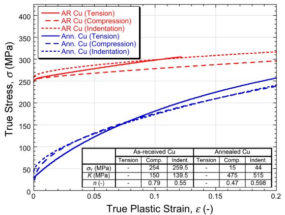
Image 2: Plots, for both materials, of true stress against true (plastic) strain. The tension plots are simply the experimental data, converted to true values, up to the strain level at which necking started. The other two are Ludwik-Hollomon plots, corresponding to the best fit sets of L-H parameter values (shown), obtained via iterative FEM simulation of the compression or indentation tests.