
4.7: Statically Equivalent Systems
- Page ID
- 70230

\( \newcommand{\vecs}[1]{\overset { \scriptstyle \rightharpoonup} {\mathbf{#1}} } \)
\( \newcommand{\vecd}[1]{\overset{-\!-\!\rightharpoonup}{\vphantom{a}\smash {#1}}} \)
\( \newcommand{\id}{\mathrm{id}}\) \( \newcommand{\Span}{\mathrm{span}}\)
( \newcommand{\kernel}{\mathrm{null}\,}\) \( \newcommand{\range}{\mathrm{range}\,}\)
\( \newcommand{\RealPart}{\mathrm{Re}}\) \( \newcommand{\ImaginaryPart}{\mathrm{Im}}\)
\( \newcommand{\Argument}{\mathrm{Arg}}\) \( \newcommand{\norm}[1]{\| #1 \|}\)
\( \newcommand{\inner}[2]{\langle #1, #2 \rangle}\)
\( \newcommand{\Span}{\mathrm{span}}\)
\( \newcommand{\id}{\mathrm{id}}\)
\( \newcommand{\Span}{\mathrm{span}}\)
\( \newcommand{\kernel}{\mathrm{null}\,}\)
\( \newcommand{\range}{\mathrm{range}\,}\)
\( \newcommand{\RealPart}{\mathrm{Re}}\)
\( \newcommand{\ImaginaryPart}{\mathrm{Im}}\)
\( \newcommand{\Argument}{\mathrm{Arg}}\)
\( \newcommand{\norm}[1]{\| #1 \|}\)
\( \newcommand{\inner}[2]{\langle #1, #2 \rangle}\)
\( \newcommand{\Span}{\mathrm{span}}\) \( \newcommand{\AA}{\unicode[.8,0]{x212B}}\)
\( \newcommand{\vectorA}[1]{\vec{#1}} % arrow\)
\( \newcommand{\vectorAt}[1]{\vec{\text{#1}}} % arrow\)
\( \newcommand{\vectorB}[1]{\overset { \scriptstyle \rightharpoonup} {\mathbf{#1}} } \)
\( \newcommand{\vectorC}[1]{\textbf{#1}} \)
\( \newcommand{\vectorD}[1]{\overrightarrow{#1}} \)
\( \newcommand{\vectorDt}[1]{\overrightarrow{\text{#1}}} \)
\( \newcommand{\vectE}[1]{\overset{-\!-\!\rightharpoonup}{\vphantom{a}\smash{\mathbf {#1}}}} \)
\( \newcommand{\vecs}[1]{\overset { \scriptstyle \rightharpoonup} {\mathbf{#1}} } \)
\( \newcommand{\vecd}[1]{\overset{-\!-\!\rightharpoonup}{\vphantom{a}\smash {#1}}} \)
\(\newcommand{\avec}{\mathbf a}\) \(\newcommand{\bvec}{\mathbf b}\) \(\newcommand{\cvec}{\mathbf c}\) \(\newcommand{\dvec}{\mathbf d}\) \(\newcommand{\dtil}{\widetilde{\mathbf d}}\) \(\newcommand{\evec}{\mathbf e}\) \(\newcommand{\fvec}{\mathbf f}\) \(\newcommand{\nvec}{\mathbf n}\) \(\newcommand{\pvec}{\mathbf p}\) \(\newcommand{\qvec}{\mathbf q}\) \(\newcommand{\svec}{\mathbf s}\) \(\newcommand{\tvec}{\mathbf t}\) \(\newcommand{\uvec}{\mathbf u}\) \(\newcommand{\vvec}{\mathbf v}\) \(\newcommand{\wvec}{\mathbf w}\) \(\newcommand{\xvec}{\mathbf x}\) \(\newcommand{\yvec}{\mathbf y}\) \(\newcommand{\zvec}{\mathbf z}\) \(\newcommand{\rvec}{\mathbf r}\) \(\newcommand{\mvec}{\mathbf m}\) \(\newcommand{\zerovec}{\mathbf 0}\) \(\newcommand{\onevec}{\mathbf 1}\) \(\newcommand{\real}{\mathbb R}\) \(\newcommand{\twovec}[2]{\left[\begin{array}{r}#1 \\ #2 \end{array}\right]}\) \(\newcommand{\ctwovec}[2]{\left[\begin{array}{c}#1 \\ #2 \end{array}\right]}\) \(\newcommand{\threevec}[3]{\left[\begin{array}{r}#1 \\ #2 \\ #3 \end{array}\right]}\) \(\newcommand{\cthreevec}[3]{\left[\begin{array}{c}#1 \\ #2 \\ #3 \end{array}\right]}\) \(\newcommand{\fourvec}[4]{\left[\begin{array}{r}#1 \\ #2 \\ #3 \\ #4 \end{array}\right]}\) \(\newcommand{\cfourvec}[4]{\left[\begin{array}{c}#1 \\ #2 \\ #3 \\ #4 \end{array}\right]}\) \(\newcommand{\fivevec}[5]{\left[\begin{array}{r}#1 \\ #2 \\ #3 \\ #4 \\ #5 \\ \end{array}\right]}\) \(\newcommand{\cfivevec}[5]{\left[\begin{array}{c}#1 \\ #2 \\ #3 \\ #4 \\ #5 \\ \end{array}\right]}\) \(\newcommand{\mattwo}[4]{\left[\begin{array}{rr}#1 \amp #2 \\ #3 \amp #4 \\ \end{array}\right]}\) \(\newcommand{\laspan}[1]{\text{Span}\{#1\}}\) \(\newcommand{\bcal}{\cal B}\) \(\newcommand{\ccal}{\cal C}\) \(\newcommand{\scal}{\cal S}\) \(\newcommand{\wcal}{\cal W}\) \(\newcommand{\ecal}{\cal E}\) \(\newcommand{\coords}[2]{\left\{#1\right\}_{#2}}\) \(\newcommand{\gray}[1]{\color{gray}{#1}}\) \(\newcommand{\lgray}[1]{\color{lightgray}{#1}}\) \(\newcommand{\rank}{\operatorname{rank}}\) \(\newcommand{\row}{\text{Row}}\) \(\newcommand{\col}{\text{Col}}\) \(\renewcommand{\row}{\text{Row}}\) \(\newcommand{\nul}{\text{Nul}}\) \(\newcommand{\var}{\text{Var}}\) \(\newcommand{\corr}{\text{corr}}\) \(\newcommand{\len}[1]{\left|#1\right|}\) \(\newcommand{\bbar}{\overline{\bvec}}\) \(\newcommand{\bhat}{\widehat{\bvec}}\) \(\newcommand{\bperp}{\bvec^\perp}\) \(\newcommand{\xhat}{\widehat{\xvec}}\) \(\newcommand{\vhat}{\widehat{\vvec}}\) \(\newcommand{\uhat}{\widehat{\uvec}}\) \(\newcommand{\what}{\widehat{\wvec}}\) \(\newcommand{\Sighat}{\widehat{\Sigma}}\) \(\newcommand{\lt}{<}\) \(\newcommand{\gt}{>}\) \(\newcommand{\amp}{&}\) \(\definecolor{fillinmathshade}{gray}{0.9}\)Key Questions
- What is an equivalent system?
- What is a resultant force?
- What is a resultant moment?
- Do you have to include both \(\vec{r}\times\vec{F}\) moments and couples to find the resultant moment?
- How can you find the simplest equivalent system?
- When will the simplest equivalent system be a wrench?
- How can you determine if two loading systems are statically equivalent?
A loading system is a combination of load forces and moments which act on an object. It can be as simple as a single force, or as complex as a three-dimensional combination of many force and moment vectors.
You will see that any loading systems may be replaced with a simpler statically equivalent system consisting of one resultant force at a specific point and one resultant moment by performing a series of equivalent transformations. Force system resultants provide a convenient representation for complex force interactions at engineering connections that we will rely on later in a variety of contexts. For now we will focus on the details of reducing a system to a single force and couple.
Depending on the original loading system, the resultant force, the resultant moment, or both may be zero. If they are both zero, it indicates that the object is in equilibrium under this load condition. If they are non-zero, the supports will need to provide an equal and opposite reaction to put the object into equilibrium.
The resultant force acting on a system, \(\vec{R}\text{,}\) can be found from adding the individual forces, \(\vec{F}_i\text{,}\) such that
\[ \vec{R}=\sum \vec{F} = \vec{F_1}+\vec{F_2}+\vec{F_3}+...\text{.} \nonumber \]
The resultant moment, \(\vec{M}_O\text{,}\) about a point \(O\text{,}\) can be found from adding all of the moments \(\vec{M}\text{,}\) about that point, including both \(\vec{r}\times\vec{F}\) moments and concentrated moments.
\[ \vec{M_{O}}=\sum \vec{M}_i =\vec{M_1}+\vec{M_2}+\vec{M_3}+... \nonumber \]
It is often more convenient to work with the scalar components of the resultant vectors, since they separate the effects in the three coordinate directions.
\begin{align*} R_x \amp =\Sigma F_x \amp {M_O}_x \amp = \Sigma M_x\\ R_y \amp =\Sigma F_y \amp {M_O}_y \amp = \Sigma M_y\\ R_z \amp =\Sigma F_z \amp {M_O}_z \amp = \Sigma M_z \end{align*}
The interactive shows an object loaded with two forces, \(\vec{A}\) and \(\vec{B}\text{,}\) and a couple-moment \(\vec{C}\) along with the equivalent resultant force \(\vec{R}\) and moment \(\vec{M}_R\text{.}\)
Force-Couple Systems.
One transformation you might want to make is to move a force to another location. While sliding a force along its line of action is fine, moving a force to another point changes its line of action and thus its rotational effect on the object, so moving is not an equivalent transformation.
Consider the cantilever beam below. In diagram (a), the load \(P\) is at the end of the beam, and in (b) it has been moved to the center. The external effects are shown in (c) and (d). Although the vertical reaction force is the \(P\) in both cases, the reaction moment at point \(O\) is is \(2P\ell\) in the first case and \(P\ell\) in the second.


(a) Force \(P\) at end of beam. (b) Force \(P\) moved to center of beam.


(c) FBD and reactions for (a). (d) FBD and reactions for (b).
Figure 4.7.2. Moving a force is not an equivalent transformation
You can move a force to a new line of action in an equivalent fashion if you add a “compensatory couple” to undo the effect of changing the line of action. This can be accomplished with of a series of individual equivalent transformations as shown in the diagram below. To move P to another location, first add two equal and opposite forces where you want the force to be, as in (b). Then recognize the couple you have formed (c), and replace it with an equivalent couple-moment. The result of this process is the equivalent force-couple system shown in diagram (d), which is statically equivalent to the original situation in (a).


(a) Original situation. (b) Add two equal and opposite forces at midpoint.


(c) Recognize couple. (d) Replace couple to produce equivalent force-couple system, with the same reactions as Figure 4.7.(c).
Figure 4.7.3. Equivalent Force-couple system
Evaluating the moment at point \(O\) at was an arbitrary choice. Any other point would give the same result. For example, in the original situation (a) force \(P\) makes a clockwise moment \(M=P\ell\) about the midpoint. When the force is moved to the center \(P\) creates no moment there, so a clockwise compensatory couple with a magnitude of \(P\ell\) must be added to maintain equivalence. This is the same result as we found previously (d). The compensatory couple has been drawn centered around the midpoint, but this too is arbitrary because concentrated moments are free vectors and can be placed at any location.
Reduction of a complex system.
Any loading system can be reduced to a statically equivalent system consisting of single force and a single moment at a specified point with the following procedure:
- Determine the resultant moment about the specified point by considering all forces and concentrated moments on the original system.
- Determine the resultant force by adding all forces acting on the original system.
- Determine the resultant moment about a point in the original system
- Create the statically equivalent system by replacing all loads with the resultant force and the resultant moment at the selected point.
Example 4.7.4. Eccentric loading.
An vertical column is supporting an eccentric load as shown.
Replace this load with an equivalent force-couple system acting at the center of the beam’s top surface.

- Answer
-
\(P = \lb{1200}\) and \(M=\ftlb{900}\) clockwise
- Solution
-
In order to move the vertical force \(\inch{9}\) to the left, a clockwise couple \(M\) must be added to maintain equivalence, where
\begin{align*} M \amp = P d\\ \amp = (\lb{1200} )(\inch{9})\\ \amp = \inlb{10,800}\\ \amp = \ftlb{900}. \end{align*}
Example 4.7.5. Equivalent Force-couple System.
Replace the system of forces in diagram (a) with an equivalent force-couple system at \(A\text{.}\)
Replace the force-couple system at \(A\) with a single equivalent force and specify its location.


(a) (b) (c)
- Answer
-
\(R = F_1 + F_2\text{,}\) \(M_A = F_1 d_1 + F_2 (d_1 + d_2)\) and \(d = M/R\)
- Solution
-
The original system is shown in (a).
Since the \(F_1\) and \(F_2\) are parallel, the magnitude of the resultant force is just the sum of the two magnitudes and it points down.
\[ R = F_1 + F_2 \nonumber \]
The resultant moment about point \(A\) is
\[ M_A = F_1 d_1 + F_2 (d_1 + d_2)\text{.} \nonumber \]
To create the equivalent system (b), the resultant force and resultant moment are placed at point \(A\text{.}\)
The system in (b) can be further simplified to eliminate the moment at \(M_A\text{,}\) by performing the process in reverse.
In (c) we place the resultant force \(R\) a distance \(d\) away from point \(A\) such that the resultant moment around point \(A\) remains the same. This distance can be found using \(M = Fd\text{.}\)
\[ d = M_A/R \nonumber \]
The systems in (a), (b), and (c) are all statically equivalent
In this example, we started with two forces. We have found two different statically equivalent systems; one with a force and a couple, the other with a single force. This latter system is simpler than the original system.
It is important to note that static equivalence applies to external effects only. When determining internal forces, such as the shear and bending moment discussed in Section 8.4 or when considering non-rigid bodies, the original loading system must be used.
Determining Equivalence.
Two complex loading systems are equivalent if they reduce to the same resultant force and the same resultant moment about any arbitrary point.
Two loading systems are statically equivalent if
- The resultant forces are the equal
- The resultant moments about some point are equal
This process is illustrated in the following example.
Example 4.7.6. Finding Statically Equivalent Loads.
Which of the three loading systems shown are statically equivalent?

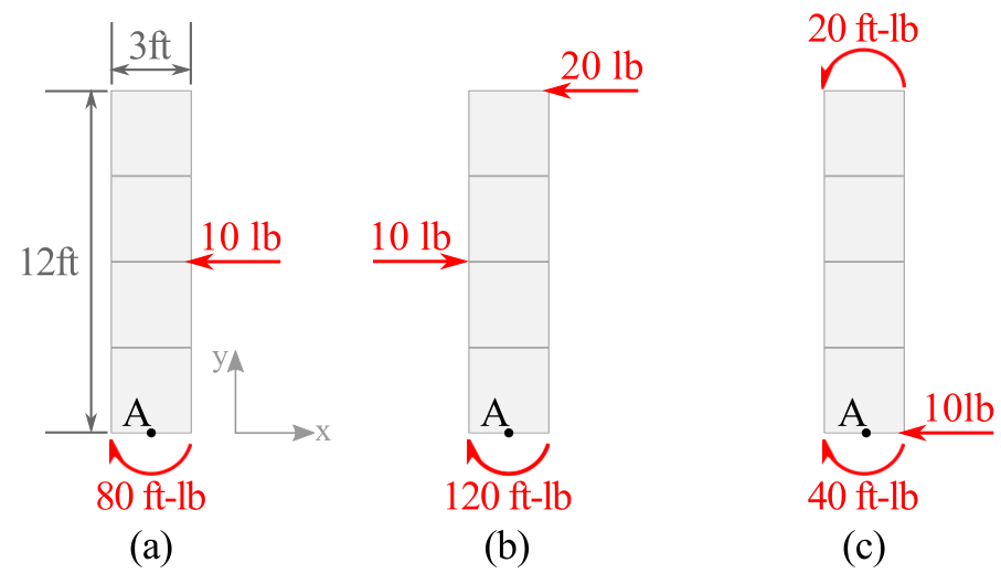
- Answer
-
(a) and (c) are statically equivalent
- Answer
-
1. Evaluate the resultant force and resultant moment for each case and compare. We choose to evaluate the resultant moment about point A, though any other point would work.
2. \begin{align*} \vec{R} \amp = \langle -10,0 \rangle \lb{}\\ \vec{M_A} \amp =-80+6(10)\\ \amp = \ftlb{-20} \end{align*}
3. \begin{align*} \vec{R}\amp=\langle -20+10,0 \rangle \lb{} \\ \amp = \langle -10,0 \rangle \lb{}\\ \vec{M}_A\amp= -120+12(20)-6(10)\\ \amp = \ftlb{60} \end{align*}
4. \begin{align*} \vec{R} \amp =\langle -10,0 \rangle \lb{}\\ \vec{M}_A \amp=-40+20+0(10) \\ \amp = \ftlb{-20} \end{align*}
Systems (a) and (c) are statically equivalent since \(\vec{R}\) and \(\vec{M}_A\) are the same in both cases. System (b) is not as its resultant moment is different than the other two.
Any load system can be simplified to its resultant force \(\vec{R}\text{,}\) and resultant couple \(\vec{M}\text{,}\) acting at any arbitrary point \(O\text{.}\) There are four common special cases which are worth highlighting individually.
Concurrent forces.
When all forces in a system are concurrent, the resultant moment about that their common intersection point will always be zero. We then need only find the resultant force and place it at the point of intersection. The resultant moment about any other point is the moment of the resultant force \(\vec{R}\) about that point.
Parallel forces.
When all forces in a system are parallel, the resultant force will act in this direction with a magnitude equal to the sum of the individual magnitudes. There will be no moment created about this axis, but we need to find the resultant moment about the other two rectangular axes. That is, if all forces act in the \(x\) direction, we need only find the resultant force in the \(x\) direction and the resultant moment about the \(y\) and \(z\) axes.
Coplanar forces.
When all forces in a system are coplanar we need only find the resultant force in this plane and the resultant moment about the axis perpendicular to this plane. That is, if all forces exist in the \(x\)-\(y\) plane, we need only to sum components in the \(x\) and \(y\) directions to find resultant force \(\vec{R}\text{,}\) and use these to determine the resultant moment about the \(z\) axis. All two-dimensional problems fall into this category.
Wrench resultant.
A wrench resultant is a special case where the resultant moment acts around the axis of the resultant force. The directions of the resultant force vector and the resultant moment vector are the same.
 For example, if the resultant force is only in the \(x\) direction and the resultant moment acts only around the \(x\) axis, this is an example of a wrench resultant. An everyday example is a screwdriver, where both the resultant force and axis of rotation are in-line with the screwdriver. A wrench resultant is considered positive if the couple vector and force vector point in the same direction, and negative if they point in opposite directions.

Any three-dimensional force-couple system may be reduced to an equivalent wrench resultant even if the resultant force and resultant moment do not initially form a wrench resultant.
To find the equivalent wrench resultant:
- First, find the resultant force \(\vec{R}\) and resultant moment \(\vec{M}\) at an arbitrary at arbitrary point, \(O\text{.}\) These need not act along the same axis.
- Resolve the resultant moment into scalar components \(M_\parallel\) and \(M_\perp\text{,}\) parallel and perpendicular to the axis of the resultant force.
- Eliminate \(M_\perp\) by moving the the resultant force away from point \(O\) by distance \(d = M_\perp/R\)
The simplified system consists of moment \(\vec{M}_\parallel\) and force \(\vec{R}\) and acting distance \(d\) away from point \(O\text{.}\) Since \(\vec{R}\) and \(\vec{M}_\parallel\) act along the same axis, the system has been reduced to a wrench resultant. Wrench resultants are the most general way to represent a complex force-couple system, but their utility is limited.