
5.2: Free Body Diagrams
- Page ID
- 70234

Key Questions
- What are the five steps to create a free-body diagram?
- What are degrees of freedom, and how do they relate to stability?
- Which reaction forces and couple-moments come from each support type?
- What are the typical support force components and couple-moment components which can be modeled from the various types of supports?
Free body diagrams are the tool that engineers use to identify the forces and moments that influence an object. They will be used extensively in statics, and you will use them again in other engineering courses so your effort to master them now is worthwhile. Although the concept is simple, students often have great difficulty with them.
Drawing a correct free-body diagram is the first and most important step in the process of solving an equilibrium problem. It is the basis for all the equilibrium equations you will write; if your free-body diagram is incorrect then your equations, analysis, and solutions will be wrong as well.
A good free-body diagram is neat and clearly drawn and contains all the information necessary to solve the equilibrium. You should take your time and think carefully about the free body diagram before you begin to write and solve equations. A straightedge, protractor and colored pencils all can help. You will inevitably make mistakes that will lead to confusion or incorrect answers; you are encouraged to think about these errors and identify any misunderstandings to avoid them in the future.
Every equilibrium problem begins by drawing and labeling a free-body diagram!
Creating Free Body Diagrams.
The basic process for drawing a free body diagrams is
- The “free-body” in free-body diagram means that the body to be analyzed must be free from the supports that are physically holding it in place
Simply sketch a quick outline of the object as if it is floating in space disconnected from everything. Do not draw free-body diagram forces on top of your problem drawing — the body needs to be drawn free of its supports.
- Select a right-handed coordinate system to use as a reference for your equilibrium equations. If you are using something other than a horizontal \(x\) axis and vertical \(y\) axis, indicate it on your diagram.
Look ahead and select a coordinate system which minimizes the number of unknown force components in your equations. The choice is technically arbitrary, but a good choice will simplify your calculations and reduce your effort. If you and another student pick different reference systems, you should both get the same answer, while expressing your work with different components.
- Add vectors arrows representing the applied forces and couple-moments acting on the body. These are often obvious. Include the body’s weight if it is non-negligible. If a vector has a known line of action, draw the arrow in that direction; if its sense is unknown, assume one. Every vector should have a descriptive variable name and a clear arrowhead indicating its direction.
- Traverse the perimeter of the object and wherever a support was removed when isolating the body, replace it with the forces and/or couple-moments which it provides. Label each reaction with a descriptive variable name and a clear arrowhead. Again, if a vector’s direction is unknown just assume one.
The reaction forces and moments provided by common two-dimensional supports are shown in Figure 5.2.1 and three dimensional support in Figure 5.2.2. Identifying the correct reaction forces and couple-moments coming from supports is perhaps the most challenging step in the entire equilibrium process.
- Verify that every dimension, angle, force, and moment is labeled with either a value or a symbolic name if the value is unknown. Supply the information needed for your calculations, but don't clutter the diagram up with unneeded information; This diagram should be a “stand-alone” presentation.
Drawing good free-body diagrams is surprisingly tricky and requires practice. Study the examples, think hard about them, do lots of problems, and learn from your errors.
Two-dimensional Reactions.
Supports supply reaction forces and moment which prevent bodies from moving when loaded. In the most basic terms, forces prevent translation, and moments prevent rotation.
The reactions supplied by a support depend on the nature of the particular support. For example in a top view, a door hinge allows the door to rotate freely but prevents it from translating. We model this as a frictionless pin that supplies a perpendicular pair of reaction forces, but no reaction moment. We can evaluate all the other physical supports in a similar way to come up with the table below. You will notice that some two-dimensional supports only restrain one degree of freedom and others restrain up to three degrees of freedom. The number of degrees of freedom directly correlates to the number of unknowns created by the support.
The table below shows typical two-dimensional support methods and the corresponding reaction forces and moments supplied each.

Figure 5.2.1. Table of common two-dimensional supports and their representation on free body diagrams.
Three-dimensional Reactions.
The main added complexity with three-dimensional objects is that there are more possible ways the the object can move, and also more possible ways to restrain it. The table below show the types of supports which are available and the corresponding reaction forces and moment. As before, your free-body digrams should show the reactions supplied by the constraints, not the constraints themselves.

Figure 5.2.2. Table of common three-dimensional supports and their associated reactions.
One new issue we face in three-dimensional problems is that reaction couples may be available but not engaged.
A support which provides a non-zero reaction is said to be engaged. Picture a crate sitting at rest on a horizontal surface with a cable attached to the top of the crate. If the cable is slack, the reaction of the cable would be available but not engaged. Instead, the floor would be supporting the full weight of the crate. If we were to remove the floor, the cable would be engaged and support the weight of the crate.

Figure 5.2.3. Available and Engaged reactions.
To get a feel for how reaction couples engage, pick up your laptop or a heavy book and hold it horizontally with your left hand. Can you feel your hand supplying an upward force to support the weight and a counter-clockwise reaction couple to keep it horizontal? Now add a similar support by gripping with your right hand. How do the forces and couple-moments change? You should have felt the force of your left hand decrease as your right hand picked up half the weight, and also noticed that the reaction couple from your left hand was no longer needed.
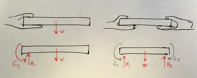
Figure 5.2.4. One hand holding an object versus two hands holding the same object.
The vertical force in your right hand engaged instead of the couple-moment of your left hand. The reaction couples from both hands are available, but the vertical forces engage first and are sufficient for equilibrium. This phenomena is described by the saying “reaction forces engage before reaction couple-moments”.
Free Body Diagram Examples.
Given that there several options for representing reaction forces and couple-moments from a support, there are different, equally valid options for drawing free-body diagrams. With experience you will learn which representation to choose to simplify the equilibrium calculations.
Possible free-body diagrams for two common situations are shown in the next two examples.
Example 5.2.5. Fixed support.
The cantilevered beam is embedded into a fixed vertical wall at \(A\text{.}\) Draw a neat, labeled, correct free-body diagram of the beam and identify the knowns and the unknowns.

- Solution
-
Begin by drawing a neat rectangle to represent the beam disconnected from its supports, then add all the known forces and couple-moments. Label the magnitudes of the loads and the known dimensions symbolically.

Choose the standard \(xy\) coordinate system, since it aligns well with the forces.
The wall at \(A\) is a fixed support which prevents the beam from translating up, down, left or right, or rotating in the plane of the page. These constraints are represented by two perpendicular forces and a concentrated moment, as shown in Figure 5.2.1. Label these unknowns as well.
The knowns in this problem are the magnitudes and directions of moment \(\vec{C}\text{,}\) forces \(\vec{B}\text{,}\) and \(\vec{D} \) and the dimensions of the beam. The unknowns are the two force components \(A_x\) and \(A_y\) and the scalar moment \(M_A\) caused by the fixed connection. If you prefer, you may represent force \(\vec{A}\) as a force of unknown magnitude acting at an unknown direction. Whether you represent it as \(x\) and \(y\) components or as a magnitude and direction, there are two unknowns associated with force \(\vec{A}\text{.}\)
The three unknown reactions can be found using the three independent equations of equilibrium we will discuss later in this chapter.
Example 5.2.6. Frictionless pin and roller.
The beam is supported by a frictionless pin at \(A\) and a rocker at \(D\text{.}\) Draw a neat, labeled, correct free-body diagram of the beam and identify the knowns and the unknowns.

- Solution
-
In this problem, the knowns are the magnitude and direction of force \(\vec{B}\) and moment \(\vec{C}\) and the dimensions of the beam.
The constraints are the frictionless pin at \(A\) and the rocker at \(D\text{.}\) The pin prevents translation but not rotation, which means two it has two unknowns, represented by either magnitude and direction, or by two orthogonal components. The rocker provides a force perpendicular to the surface it rests on, which is \(\ang{30}\) from the horizontal. This means that the line of action of force \(\vec{D}\) is \(\ang{30}\) from the vertical, giving us its direction but not its sense or magnitude
To draw the free body diagram, start with a neat rectangle to representing the beam disconnected from its supports, then draw and label known force \(B\) and moment \(C\) and the dimensions.

Add forces \(A_x\) and \(A_y\) representing vector \(\vec{A}\) and force \(\vec{D}\) at \(D\text{,}\) acting \(\ang{30}\) from the vertical.
When a force has a known line of action as with force \(\vec{D}\text{,}\) draw it acting along that line; don’t break it into components. When it is not obvious which way a reaction force actually points along its lines of action, just make your best guess and place an arrowhead accordingly. Your calculations will confirm or refute your guess later.
As in the previous example, you could alternately represent force \(\vec{A}\) as an unknown magnitude acting in an unknown direction, though there is no particular advantage to doing so in this case.
