
6.6: Frames and Machines
- Page ID
- 70247

\( \newcommand{\vecs}[1]{\overset { \scriptstyle \rightharpoonup} {\mathbf{#1}} } \)
\( \newcommand{\vecd}[1]{\overset{-\!-\!\rightharpoonup}{\vphantom{a}\smash {#1}}} \)
\( \newcommand{\dsum}{\displaystyle\sum\limits} \)
\( \newcommand{\dint}{\displaystyle\int\limits} \)
\( \newcommand{\dlim}{\displaystyle\lim\limits} \)
\( \newcommand{\id}{\mathrm{id}}\) \( \newcommand{\Span}{\mathrm{span}}\)
( \newcommand{\kernel}{\mathrm{null}\,}\) \( \newcommand{\range}{\mathrm{range}\,}\)
\( \newcommand{\RealPart}{\mathrm{Re}}\) \( \newcommand{\ImaginaryPart}{\mathrm{Im}}\)
\( \newcommand{\Argument}{\mathrm{Arg}}\) \( \newcommand{\norm}[1]{\| #1 \|}\)
\( \newcommand{\inner}[2]{\langle #1, #2 \rangle}\)
\( \newcommand{\Span}{\mathrm{span}}\)
\( \newcommand{\id}{\mathrm{id}}\)
\( \newcommand{\Span}{\mathrm{span}}\)
\( \newcommand{\kernel}{\mathrm{null}\,}\)
\( \newcommand{\range}{\mathrm{range}\,}\)
\( \newcommand{\RealPart}{\mathrm{Re}}\)
\( \newcommand{\ImaginaryPart}{\mathrm{Im}}\)
\( \newcommand{\Argument}{\mathrm{Arg}}\)
\( \newcommand{\norm}[1]{\| #1 \|}\)
\( \newcommand{\inner}[2]{\langle #1, #2 \rangle}\)
\( \newcommand{\Span}{\mathrm{span}}\) \( \newcommand{\AA}{\unicode[.8,0]{x212B}}\)
\( \newcommand{\vectorA}[1]{\vec{#1}} % arrow\)
\( \newcommand{\vectorAt}[1]{\vec{\text{#1}}} % arrow\)
\( \newcommand{\vectorB}[1]{\overset { \scriptstyle \rightharpoonup} {\mathbf{#1}} } \)
\( \newcommand{\vectorC}[1]{\textbf{#1}} \)
\( \newcommand{\vectorD}[1]{\overrightarrow{#1}} \)
\( \newcommand{\vectorDt}[1]{\overrightarrow{\text{#1}}} \)
\( \newcommand{\vectE}[1]{\overset{-\!-\!\rightharpoonup}{\vphantom{a}\smash{\mathbf {#1}}}} \)
\( \newcommand{\vecs}[1]{\overset { \scriptstyle \rightharpoonup} {\mathbf{#1}} } \)
\(\newcommand{\longvect}{\overrightarrow}\)
\( \newcommand{\vecd}[1]{\overset{-\!-\!\rightharpoonup}{\vphantom{a}\smash {#1}}} \)
\(\newcommand{\avec}{\mathbf a}\) \(\newcommand{\bvec}{\mathbf b}\) \(\newcommand{\cvec}{\mathbf c}\) \(\newcommand{\dvec}{\mathbf d}\) \(\newcommand{\dtil}{\widetilde{\mathbf d}}\) \(\newcommand{\evec}{\mathbf e}\) \(\newcommand{\fvec}{\mathbf f}\) \(\newcommand{\nvec}{\mathbf n}\) \(\newcommand{\pvec}{\mathbf p}\) \(\newcommand{\qvec}{\mathbf q}\) \(\newcommand{\svec}{\mathbf s}\) \(\newcommand{\tvec}{\mathbf t}\) \(\newcommand{\uvec}{\mathbf u}\) \(\newcommand{\vvec}{\mathbf v}\) \(\newcommand{\wvec}{\mathbf w}\) \(\newcommand{\xvec}{\mathbf x}\) \(\newcommand{\yvec}{\mathbf y}\) \(\newcommand{\zvec}{\mathbf z}\) \(\newcommand{\rvec}{\mathbf r}\) \(\newcommand{\mvec}{\mathbf m}\) \(\newcommand{\zerovec}{\mathbf 0}\) \(\newcommand{\onevec}{\mathbf 1}\) \(\newcommand{\real}{\mathbb R}\) \(\newcommand{\twovec}[2]{\left[\begin{array}{r}#1 \\ #2 \end{array}\right]}\) \(\newcommand{\ctwovec}[2]{\left[\begin{array}{c}#1 \\ #2 \end{array}\right]}\) \(\newcommand{\threevec}[3]{\left[\begin{array}{r}#1 \\ #2 \\ #3 \end{array}\right]}\) \(\newcommand{\cthreevec}[3]{\left[\begin{array}{c}#1 \\ #2 \\ #3 \end{array}\right]}\) \(\newcommand{\fourvec}[4]{\left[\begin{array}{r}#1 \\ #2 \\ #3 \\ #4 \end{array}\right]}\) \(\newcommand{\cfourvec}[4]{\left[\begin{array}{c}#1 \\ #2 \\ #3 \\ #4 \end{array}\right]}\) \(\newcommand{\fivevec}[5]{\left[\begin{array}{r}#1 \\ #2 \\ #3 \\ #4 \\ #5 \\ \end{array}\right]}\) \(\newcommand{\cfivevec}[5]{\left[\begin{array}{c}#1 \\ #2 \\ #3 \\ #4 \\ #5 \\ \end{array}\right]}\) \(\newcommand{\mattwo}[4]{\left[\begin{array}{rr}#1 \amp #2 \\ #3 \amp #4 \\ \end{array}\right]}\) \(\newcommand{\laspan}[1]{\text{Span}\{#1\}}\) \(\newcommand{\bcal}{\cal B}\) \(\newcommand{\ccal}{\cal C}\) \(\newcommand{\scal}{\cal S}\) \(\newcommand{\wcal}{\cal W}\) \(\newcommand{\ecal}{\cal E}\) \(\newcommand{\coords}[2]{\left\{#1\right\}_{#2}}\) \(\newcommand{\gray}[1]{\color{gray}{#1}}\) \(\newcommand{\lgray}[1]{\color{lightgray}{#1}}\) \(\newcommand{\rank}{\operatorname{rank}}\) \(\newcommand{\row}{\text{Row}}\) \(\newcommand{\col}{\text{Col}}\) \(\renewcommand{\row}{\text{Row}}\) \(\newcommand{\nul}{\text{Nul}}\) \(\newcommand{\var}{\text{Var}}\) \(\newcommand{\corr}{\text{corr}}\) \(\newcommand{\len}[1]{\left|#1\right|}\) \(\newcommand{\bbar}{\overline{\bvec}}\) \(\newcommand{\bhat}{\widehat{\bvec}}\) \(\newcommand{\bperp}{\bvec^\perp}\) \(\newcommand{\xhat}{\widehat{\xvec}}\) \(\newcommand{\vhat}{\widehat{\vvec}}\) \(\newcommand{\uhat}{\widehat{\uvec}}\) \(\newcommand{\what}{\widehat{\wvec}}\) \(\newcommand{\Sighat}{\widehat{\Sigma}}\) \(\newcommand{\lt}{<}\) \(\newcommand{\gt}{>}\) \(\newcommand{\amp}{&}\) \(\definecolor{fillinmathshade}{gray}{0.9}\)Key Questions
- How are frames and machines different from trusses?
- Why can the method of joints and method of sections not be used for frames and machines?
- How do we identify if a structure is independently rigid?
- How do we apply equilibrium equations to each member of the structure, and ensure that the sense of a force appearing on multiple free-body diagrams is consistent?
Frame and machines are engineering structures that contain at least one multi-force member. As their name implies, multi-force members have more than two concentrated loads, distributed loads, and/or couples applied to them and therefore are not two-force members. Note that all bodies we investigated in Chapter 5 were all multi-force bodies.
Analyzing a frame or machine means determining all applied, reaction, and internal forces and couples acting on the structure and all of its parts.
Frames are rigid, stationary structures designed to support loads and must include at least one multi-force member.
Machines are non-rigid structures where the parts can move relative to one another. Generally they have an input and an output force and are designed produce a mechanical advantage. Note that all machines in this text are in static equilibrium by their interacting and applied forces.
Though there is a design difference between frames and machines they are grouped together because they can both be analyzed using the same process, which is the subject of this section.
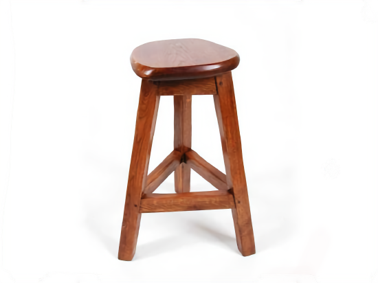
Figure 6.6.1. Frames are rigid objects containing multi-force members.
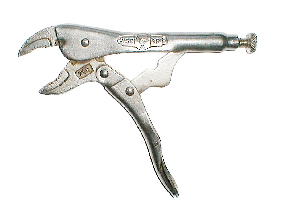
Figure 6.6.2. Machines contain multi-force members that can move relative to one another.
Analyzing frames and machines involves disassembling the structure into individual rigid bodies; we “take the structure apart” and analyze each part separately. Each component is analyzed as an independent rigid body. This leads to equilibrium equations for each component, and by Newton’s Third Law, every interaction force and couple is one half of a complementary pair. The interacting force of body \(A\) on \(B\) is equal and opposite to the force of body \(B\) on body \(A\) and the free-body diagrams must reflect this.
In Chapter 5 we saw that each two-dimensional free-body diagram results in up to three linearly independent equations. By disassembling the structure we now have more free-body diagrams available, and can use them to find more unknown values. Here’s a few more details on the number of equations that come from each type of two-dimensional free-body diagram:
- Two-force members. One equation. Two-force members can be recognized as either a cable or a weightless link with all forces coming from two frictionless pins. The force at one pin is equal and opposite to the force on the other placing the body in tension or compression.
- Objects with concurrent forces and no couple-moments. Two equations These are the problems you solved in Chapter 3\. There are two equations available \(\Sigma F_x = 0\) and \(\Sigma F_y = 0\text{.}\)
- Multi-force rigid body with offset forces and/or couples. Three equations These are the most general body types where you can use \(\Sigma F_x = 0\text{,}\) \(\Sigma F_y = 0\text{,}\) and\(\Sigma M = 0\) to solve for three unknowns.
Procedure
The process used to analyze frames and machines is outlined below
- Determine if the entire structure as independently rigid. An independently rigid structure will hold it shape even when separated from its supports. Look for triangles formed among the members, as triangles are inherently rigid. If it is not independently rigid, the structure will collapse when the supports are removed.
If the structure is independently rigid, model it as a single rigid body and determine the reaction forces. If the structure is not independently rigid then skip this step.
- Draw a free-body diagram for each of the members in the structure. You must represent all forces acting on each member, including:
All interaction forces and couples between connected bodies must be shown as equal-and-opposite action-reaction pairs.
- Applied forces and couples and the weights of the components if non-negligible.
- Interaction forces due to two-force members. There will be force of unknown magnitude but the known direction at points connected to two-force members. The forces will act along the line between the two connection points.
- All reaction forces and couples at the connection points between members. Forces with an unknown magnitude and direction are usually represented by unknown \(x\) and \(y\) components, but can also be represented as a force with unknown magnitude acting in an unknown direction.

Figure 6.6.3. Free-body digram of a rigid frame with pin at \(A\text{,}\) roller at \(E\text{,}\) and load at \(F\text{.}\)

Figure 6.6.4. Free body diagrams of the individual components. External forces are red, exposed action-reaction pairs in blue.
3. Write out the equilibrium equations for each free-body diagram.
4. Solve the equilibrium equations for the unknowns. You can do this algebraically, solving for one variable at a time, or you can use matrix equations to solve for everything at once. Negative magnitudes indicate that the assumed direction of that term was incorrect, and the actual force/moment is opposite the assumed direction.
- Thinking Deeper 6.6.5. Why does the Method of Joints work on trusses but fail on Frames and Machines?
-
We can solve trusses using the methods of joints and method of sections because all members of a simple truss are two-force bodies. Cutting a truss member exposes an internal force which has an unknown scalar magnitude, but a known line of action. The force acts along the axis of the member, and causes no bending if the member is straight. Cutting a truss member exposes one unknown.
Frames and machines are made of multi-force members and cutting these, in general, exposes:
- A force with an unknown magnitude acting in an unknown direction, and
- A bending moment at the plane of the cut.
Cutting a two-dimensional multi-force member exposes three unknowns, and six are exposed for a three-dimensional body. The number of unknowns quickly eclipses the available equations rendering the problem impossible to solve.
Bottom line: use method of sections and joints only for trusses made of two-force straight members; for all other multi-force rigid body systems draw and analyze free-body diagrams of the components.