
11.3: Derivation of Slope-Deflection Equations
- Page ID
- 42992

To derive the slope-deflection equations, consider a beam of length \(L\) and of constant flexural rigidity \(EI\) loaded as shown in Figure 11.1a. The member experiences the end moments \(M_{A B}\) and \(M_{A B}\) at \(A\) and \(B\), respectively, and undergoes the deformed shape shown in Figure 11.1b, with the assumption that the right end \(B\) of the member settles by an amount \(\Delta\). The end moments are the summation of the moments caused by the rotations of the joints at the ends \(A\) and \(B\) \(\theta_{A}\) and \(\theta_{B}\)) of the beam, the chord rotation (\(\psi=\frac{\Delta}{l}\). and the fixity at both ends referred to as fixed end moments (\(M_{A B}^{\bar{F}}\) and \(M_{B A}^{\bar{F}}\)).
The rotations at the joints of the beam can be expressed mathematically as follows: \[\theta_{A}=\beta_{A}+\psi\]
\[\theta_{B}=\beta_{B}+\psi\]
where
\(\beta_{A}\), \(\beta_{B}\) = end rotations caused by moments \(M_{A B}\) and \(M_{B A}\), respectively.
\(\psi\) = chord rotation caused by settlement of end \(B\).
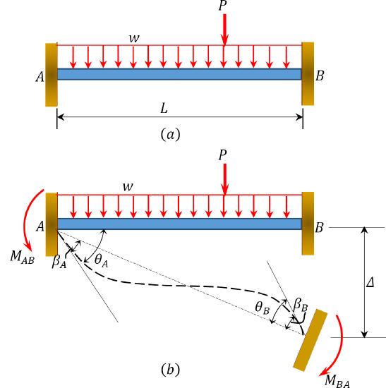
\(Fig. 11.1\). Beam.
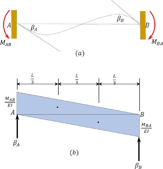
\(Fig. 11.2\). End moments due to rotations \(\beta_{A}\) and \(\beta_{B}\).
According to the moment-area theorem, the change in slope for a particular beam equals the end shear force of the beam when it is loaded with the \(\frac{M}{E I}\) diagram. Thus, for the beam under consideration, the rotations \(\beta_{A}\) and \(\beta_{B}\), shown in Figure 11.2, are obtained as follows:
 \(\begin{array}{l}
\left(+\sum M_{B}=0 ;-\beta_{A} L+\left(\frac{1}{2}\right)\left(\frac{M_{A B}}{E I}\right)(L)\left(\frac{2}{3} L\right)-\left(\frac{1}{2}\right)\left(\frac{M_{B A}}{E I}\right)(L)\left(\frac{1}{3} L\right)=0\right. \\
\beta_{A}=\frac{\left(\frac{1}{2}\right)\left(\frac{M_{A B}}{E I}\right)(L)\left(\frac{2}{3} L\right)-\left(\frac{1}{2}\right)\left(\frac{M_{B A}}{E I}\right)(L)\left(\frac{1}{3} L\right)}{L}
\end{array}\)
\[=\frac{L}{6 E I}\left(2 M_{A B}-M_{B A}\right)\]
Similarly, taking the moment about end \(A\) to determine \(\beta_{B}\) suggests the following:
\(\begin{array}{l}
+\sum M_{A}=0 ; \beta_{B} L+\left(\frac{1}{2}\right)\left(\frac{M_{B A}}{E I}\right)(L)\left(\frac{2}{3} L\right)-\left(\frac{1}{2}\right)\left(\frac{M_{A B}}{E I}\right)(L)\left(\frac{1}{3} L\right)=0\right. \\
\beta_{B}=\frac{\left(\frac{1}{2}\right)\left(\frac{M_{B A}}{E I}\right)(L)\left(\frac{2}{3} L\right)-\left(\frac{1}{2}\right)\left(\frac{M_{A B}}{E I}\right)(L)\left(\frac{1}{3} L\right)}{L}
\end{array}\)
\[=\frac{L}{6 E I}\left(2 M_{B A}-M_{A B}\right)\]
Solving equations 11.3 and 11.4 suggests the following: \[M_{A B}=\frac{4 E I}{L} \beta_{A}+\frac{2 E I}{L} \beta_{B}\]
\[M_{B A}=\frac{2 E I}{L} \beta_{A}+\frac{4 E I}{L} \beta_{B}\]
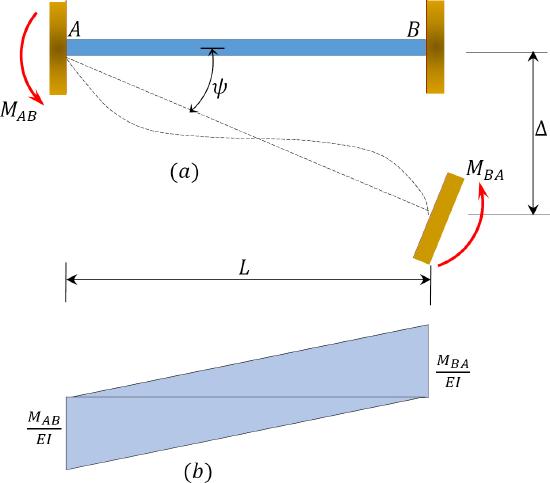
\(Fig. 11.3\). End moments due to end rotations (\(\beta_{A}\) and \(\beta_{B}\)) and chord rotation (\(\psi\)).
Solving equations 11.1 and 11.2 for \(\beta_{A}\) and \(\beta_{B}\) and substituting them into equations 11.5 and 11.6 suggests the following: \[M_{A B}=\frac{4 E I}{L}\left(\theta_{A}-\psi\right)+\frac{2 E I}{L}\left(\theta_{B}-\psi\right)\]
\[M_{B A}=\frac{2 E I}{L}\left(\theta_{A}-\psi\right)+\frac{4 E I}{L}\left(\theta_{B}-\psi\right)\]
Putting \(\psi=\frac{\Delta}{L}\) into equations 10.10 and 10.11 suggests the following: \[M_{A B}=\frac{4 E I}{L} \theta_{A}+\frac{2 E I}{L} \theta_{B}-\frac{6 E I}{L^{2}} \Delta\]
\[M_{B A}=\frac{2 E I}{L} \theta_{A}+\frac{4 E I}{L} \theta_{B}-\frac{6 E I}{L^{2}} \Delta\]
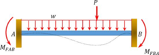
\(Fig. 11.4\). End moment due to end rotations (\(\beta_{A}\) and \(\beta_{B}\)), chord rotation (\(\psi\)), and fixed-end moments (\(M_{A B}^{F}\) and \(M_{B A}^{F}\)).
The final end moments can then be computed as the summation of the moments caused by slopes, deflections, and fixed-end moments, as follows: \[\begin{array}{l}
M_{A B}=2 E K\left(2 \theta_{A}+\theta_{B}-3 \psi\right)+M_{A B}^{F} \\
M_{B A}=2 E K\left(\theta_{A}+2 \theta_{B}-3 \psi\right)+M_{B A}^{F}
\end{array}\]
where
\(K=\frac{I}{L}=\) stiffness factor.