
5.3: Sensors Using Light
- Page ID
- 14797

The small form factor and low price of light-sensitive semiconductors have led to a proliferation of light-based sensing relying on a multitude of physical effects. These include reflection, phase shift, and time of flight.
5.3.1. Reflection
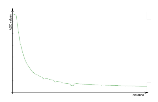
Reflection is one of the principles that is easiest to exploit: the closer an object is, the more it reflects light shined at it. This allows to easily measure distance to objects that reflect light well and are not too far away. In order to make these sensors as independent from an object’s color (but unfortunately not totally independent), infrared is most commonly chosen. A distance sensor is made from two components: an emitter and a receiver. They work by emitting an infrared signal and then measuring the strength of the reflected signal. A typical response is shown in Figure 5.3.1. The values obtained at an analog-digital converter correspond to the voltage at the infrared receiver and are saturated for low distances (flat line), and quadratically fall off thereafter.
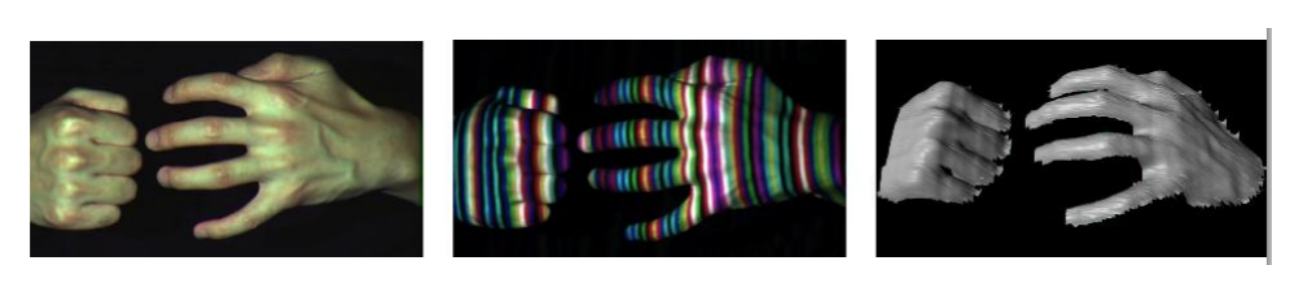
When using more than one infrared sensor/emitter pair, e.g., using a camera and a projector not only allows to measure the distance of many points at once, but also to assess the structure of the environment by calculating its impact on the deformation of patterns. For example a straight line becomes a curve when projected onto a round surface. This approach is known as structured light and illustrated in Figure 5.3.2. Thanks to the continuously increasing efficiency of computational systems, a light-weight version of such an approach has become feasible to be implemented at small scale and low cost at around 2010, and emerged as a novel standard in robotic sensing.
Instead of using line patterns, infrared-based depth image sensors use a speckle pattern (a collection of randomly distributed dots with varying distances), and two computer vision concepts: depth from focus and depth from stereo. When using a lens with a narrow focal depth, objects that are closer or farther away appear blurred (you can easily observe this on professional portrait photos, which often use this effect for aesthetic purposes). Measuring the “bluriness” of a scene (for known camera parameters) therefore allows for an initial estimate of depth. Depth from stereo instead works by measuring the disparity of the same object appearing in two images taken by cameras that are a known distance apart. Being able to identify the same object in both frames allows to calculate this disparity, and from there the distance of the object. (The farther the object is away, the smaller is the disparity.) This is where the speckle pattern comes in handy, which simply requires to search for blobs with similar size that are close to each other.
5.3.2. Phase shift
As you can see in Figure 5.3.1, reflection can only be precise if distances are short. Instead of measuring the strength (aka amplitude) of the reflected signal, laser distance sensors measure the phase difference of the reflected wave. In order to do this, the emitted light is modulated with a wave-length that exceeds the maximum distance the scanner can measure. If you would use visible light and do this much slower, you would see a light that keeps getting brighter, then getting darker, briefly turns off and then starts getting brighter again. Thus, if you would plot the amplitude, i.e. its brightness, of the emitted signal vs. time you would see a wave that has zero-crossings when the light is dark. As light travels with the speed of light, this wave propagates through space with a constant distance (the wavelength) between its zero crossings. When it gets reflected, the same wave travels back (or at least parts of it that get scattered right back). For example, modern laser scanners emit signals with a frequency of 5 MHz (turning off 5 million times in one second). Together with the speed of light of approximately 300,000km/s, this leads to a wavelength of 60m and makes such a laser scanner useful up to 30m.
When the laser is now at a distance that corresponds exactly to one half the wave-length, the reflected signal it measures will be dark at the exact same time its emitted wave goes through a zero-crossing. Going closer to the obstacle results in an offset that can be measured. As the emitter knows the shape of the wave it emitted, it can calculate the phase difference between emitted and received signal. Knowing the wave-length it can now calculate the distance. As this process is independent from ambient light (unless it has the exact same frequency as the laser being used), the estimates can be very precise. This is in contrast to a sensor that uses signal strength. As the signal strength decays at least quadratically, small errors, e.g. due to fluctuations in the power supply that drives the emitting light, noise in the analog-digital converter, or simply differences in the reflecting surface have drastic impact on the accuracy and precision (see below for a more formal definition of this term).
As the laser distance measurement process is fast, such lasers can be combined with rotating mirrors to sweep larger areas, known as Laser Range Scanners. Such systems have been combined into packages consisting of up to 64 scanning lasers, providing a depth map around a car while driving, e.g. It is also possible to modulate projected images with a phase-changing signal, which is the operational principle of early “time-offlight” cameras, which is not an accurate description of their operation, however.
5.3.3. Time-of-flight
The most precise distance measurements light can provide is by measuring its time of flight. This can be done by counting the time a signal from the emitter becomes visible in the receiver. As light travels very fast (3,000,000,000m/s), this requires highspeed electronics that can measure time periods smaller than nano-seconds in order to achieve centimeter accuracy. In practice this is done by combining the receiver with a very fast (electronic) shutter that operates at the same frequency with which light is emitted. As this timing is known, one can infer the time light must have been traveling by measuring the quantity of photons that have made it back from the reflective surface within one shutter period. Considering a concrete example, light travels 15m in 50ns. Therefore, it will take a pulse 50ns to return from an object at a distance of 7.5m. If the camera sends out a pulse of 50ns length and then closes the receiver with a shutter, the receiver will receive more photons the closer the object is, but no photons if the object is farther away than 7.5m. Given a fast enough and precise circuit that acts as a shutter, it is sufficient to measure the actual amount of light that returns from the emitter.