
5.6: Analysis of Frames and Machines
- Page ID
- 111339

\( \newcommand{\vecs}[1]{\overset { \scriptstyle \rightharpoonup} {\mathbf{#1}} } \)
\( \newcommand{\vecd}[1]{\overset{-\!-\!\rightharpoonup}{\vphantom{a}\smash {#1}}} \)
\( \newcommand{\dsum}{\displaystyle\sum\limits} \)
\( \newcommand{\dint}{\displaystyle\int\limits} \)
\( \newcommand{\dlim}{\displaystyle\lim\limits} \)
\( \newcommand{\id}{\mathrm{id}}\) \( \newcommand{\Span}{\mathrm{span}}\)
( \newcommand{\kernel}{\mathrm{null}\,}\) \( \newcommand{\range}{\mathrm{range}\,}\)
\( \newcommand{\RealPart}{\mathrm{Re}}\) \( \newcommand{\ImaginaryPart}{\mathrm{Im}}\)
\( \newcommand{\Argument}{\mathrm{Arg}}\) \( \newcommand{\norm}[1]{\| #1 \|}\)
\( \newcommand{\inner}[2]{\langle #1, #2 \rangle}\)
\( \newcommand{\Span}{\mathrm{span}}\)
\( \newcommand{\id}{\mathrm{id}}\)
\( \newcommand{\Span}{\mathrm{span}}\)
\( \newcommand{\kernel}{\mathrm{null}\,}\)
\( \newcommand{\range}{\mathrm{range}\,}\)
\( \newcommand{\RealPart}{\mathrm{Re}}\)
\( \newcommand{\ImaginaryPart}{\mathrm{Im}}\)
\( \newcommand{\Argument}{\mathrm{Arg}}\)
\( \newcommand{\norm}[1]{\| #1 \|}\)
\( \newcommand{\inner}[2]{\langle #1, #2 \rangle}\)
\( \newcommand{\Span}{\mathrm{span}}\) \( \newcommand{\AA}{\unicode[.8,0]{x212B}}\)
\( \newcommand{\vectorA}[1]{\vec{#1}} % arrow\)
\( \newcommand{\vectorAt}[1]{\vec{\text{#1}}} % arrow\)
\( \newcommand{\vectorB}[1]{\overset { \scriptstyle \rightharpoonup} {\mathbf{#1}} } \)
\( \newcommand{\vectorC}[1]{\textbf{#1}} \)
\( \newcommand{\vectorD}[1]{\overrightarrow{#1}} \)
\( \newcommand{\vectorDt}[1]{\overrightarrow{\text{#1}}} \)
\( \newcommand{\vectE}[1]{\overset{-\!-\!\rightharpoonup}{\vphantom{a}\smash{\mathbf {#1}}}} \)
\( \newcommand{\vecs}[1]{\overset { \scriptstyle \rightharpoonup} {\mathbf{#1}} } \)
\(\newcommand{\longvect}{\overrightarrow}\)
\( \newcommand{\vecd}[1]{\overset{-\!-\!\rightharpoonup}{\vphantom{a}\smash {#1}}} \)
\(\newcommand{\avec}{\mathbf a}\) \(\newcommand{\bvec}{\mathbf b}\) \(\newcommand{\cvec}{\mathbf c}\) \(\newcommand{\dvec}{\mathbf d}\) \(\newcommand{\dtil}{\widetilde{\mathbf d}}\) \(\newcommand{\evec}{\mathbf e}\) \(\newcommand{\fvec}{\mathbf f}\) \(\newcommand{\nvec}{\mathbf n}\) \(\newcommand{\pvec}{\mathbf p}\) \(\newcommand{\qvec}{\mathbf q}\) \(\newcommand{\svec}{\mathbf s}\) \(\newcommand{\tvec}{\mathbf t}\) \(\newcommand{\uvec}{\mathbf u}\) \(\newcommand{\vvec}{\mathbf v}\) \(\newcommand{\wvec}{\mathbf w}\) \(\newcommand{\xvec}{\mathbf x}\) \(\newcommand{\yvec}{\mathbf y}\) \(\newcommand{\zvec}{\mathbf z}\) \(\newcommand{\rvec}{\mathbf r}\) \(\newcommand{\mvec}{\mathbf m}\) \(\newcommand{\zerovec}{\mathbf 0}\) \(\newcommand{\onevec}{\mathbf 1}\) \(\newcommand{\real}{\mathbb R}\) \(\newcommand{\twovec}[2]{\left[\begin{array}{r}#1 \\ #2 \end{array}\right]}\) \(\newcommand{\ctwovec}[2]{\left[\begin{array}{c}#1 \\ #2 \end{array}\right]}\) \(\newcommand{\threevec}[3]{\left[\begin{array}{r}#1 \\ #2 \\ #3 \end{array}\right]}\) \(\newcommand{\cthreevec}[3]{\left[\begin{array}{c}#1 \\ #2 \\ #3 \end{array}\right]}\) \(\newcommand{\fourvec}[4]{\left[\begin{array}{r}#1 \\ #2 \\ #3 \\ #4 \end{array}\right]}\) \(\newcommand{\cfourvec}[4]{\left[\begin{array}{c}#1 \\ #2 \\ #3 \\ #4 \end{array}\right]}\) \(\newcommand{\fivevec}[5]{\left[\begin{array}{r}#1 \\ #2 \\ #3 \\ #4 \\ #5 \\ \end{array}\right]}\) \(\newcommand{\cfivevec}[5]{\left[\begin{array}{c}#1 \\ #2 \\ #3 \\ #4 \\ #5 \\ \end{array}\right]}\) \(\newcommand{\mattwo}[4]{\left[\begin{array}{rr}#1 \amp #2 \\ #3 \amp #4 \\ \end{array}\right]}\) \(\newcommand{\laspan}[1]{\text{Span}\{#1\}}\) \(\newcommand{\bcal}{\cal B}\) \(\newcommand{\ccal}{\cal C}\) \(\newcommand{\scal}{\cal S}\) \(\newcommand{\wcal}{\cal W}\) \(\newcommand{\ecal}{\cal E}\) \(\newcommand{\coords}[2]{\left\{#1\right\}_{#2}}\) \(\newcommand{\gray}[1]{\color{gray}{#1}}\) \(\newcommand{\lgray}[1]{\color{lightgray}{#1}}\) \(\newcommand{\rank}{\operatorname{rank}}\) \(\newcommand{\row}{\text{Row}}\) \(\newcommand{\col}{\text{Col}}\) \(\renewcommand{\row}{\text{Row}}\) \(\newcommand{\nul}{\text{Nul}}\) \(\newcommand{\var}{\text{Var}}\) \(\newcommand{\corr}{\text{corr}}\) \(\newcommand{\len}[1]{\left|#1\right|}\) \(\newcommand{\bbar}{\overline{\bvec}}\) \(\newcommand{\bhat}{\widehat{\bvec}}\) \(\newcommand{\bperp}{\bvec^\perp}\) \(\newcommand{\xhat}{\widehat{\xvec}}\) \(\newcommand{\vhat}{\widehat{\vvec}}\) \(\newcommand{\uhat}{\widehat{\uvec}}\) \(\newcommand{\what}{\widehat{\wvec}}\) \(\newcommand{\Sighat}{\widehat{\Sigma}}\) \(\newcommand{\lt}{<}\) \(\newcommand{\gt}{>}\) \(\newcommand{\amp}{&}\) \(\definecolor{fillinmathshade}{gray}{0.9}\)The process used to analyze frames and machines involves breaking the structure down into individual components in order to solve for the forces acting on each component. Unlike trusses, not all the members in a frame or machine are two force members. When we have non-two force members, the forces acting on those individual members will be more complicated than just a simple tension or compression force.
The Process for Analyzing Frames and Machines:
The process used to analyze frames and machines begins in much the same way as with trusses, but will differ after identifying the external forces.
To start, if the joints are not already labeled, we will begin by labeling all the joints with a letter. The exact order you label the joints in are not important, so long as you are consistent in your work. We will refer to joints by their letter (A, B, C...) and we will refer to the members by the joints they connect (ABC, BD, CDE...). It should be noted that unlike trusses, the members may now connect more than two joints.
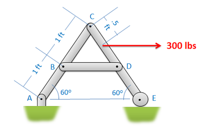 Figure \(\PageIndex{1}\): The first step in the analysis of frames and machines is to label the members.
Next you will need to determine if we can analyze the entire structure as a rigid body. In order to do this, the structure needs to be independently rigid. This means that it would be rigid even if we separated it from its supports. If the structure is independently rigid (no machines, and only some frames will be independently rigid), then we can analyze the structure as a single rigid body to determine the reaction forces acting on the structure. To do this, you would draw a free body diagram of the whole structure, write out the equilibrium equations, and solve for the unknown reaction forces. If the structure is not independently rigid than we cannot analyze the structure as a whole to determine external forces in this way.
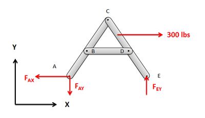
Figure \(\PageIndex{2}\): If, and only if, the structure is independently rigid, you should analyze the whole structure as a single rigid body to solve for the reaction forces.
Next we will break the structure down into individual components and draw a free body diagram for each component. We can do the analysis one component at a time, or we can draw all the free body diagrams at once. The free body diagram should include all known and unknown forces acting on each of the components, as well as key angles and distances.
When drawing these free body diagrams, there are a few things to consider:
- First any external reaction or load forces should only show up on the component that they are directly acting on. Those load forces will act on other members only through the connections in the structure.
- Second, when examining the forces that the members exert on one another, consider the types of connections and the forces they exert. Remember that (in 2D) fixed connections exert forces in the x and y direction as well as a moment, pin joints exert forces in the x and y direction (but no moment) and rollers or sliding joints only exert a force perpendicular to the surface/
- Third identify any two force members in the structure and use that to simplify the analysis. At their connection points they will cause a force with an unknown magnitude but a known direction (the forces will act along the line between the two connection points on the member). This means that even at a pin joint, a two force member will result in a single unknown force rather than two unknown forces.
- Finally, remember that the forces at each of the connection points will be a Newton's Third Law pair. This means that if one member exerts some force on some other member, then the second member will exert an equal and opposite force back on the first. When we draw out our unknown forces at the connection points, we must make sure that if we draw forces in a certain direction on one member, we draw them in the opposite direction on the connected other connected member.
-
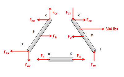
Figure \(\PageIndex{3}\): Separate the structure into individual components and draw a free body diagram of each component. It is important to remember that the forces at each connection point are a Newton's Third Law pair.
Next we will write out the equilibrium equations for each of the components. As each component is a rigid body, each component will have its own set of equilibrium equations. That being said, the unknown forces will likely show up in more than one set of these equations because of the third law pairs.
For 2D problems you will have three possible equations for each component, two force equations and one moment equation
\[ \sum \vec{F} = 0 \quad\quad\quad\quad \sum \vec{M} = 0 \] \[ \sum F_x = 0 \, ; \,\,\, \sum F_y = 0 \, ; \,\,\, \sum M_z = 0 \]
For 3D problems you will have six possible equations for each section: three force equations and three moment equations.
\[ \sum \vec{F} = 0 \] \[ \sum F_x = 0 \, ; \,\,\, \sum F_y = 0 \, ; \,\,\, \sum F_z = 0 \] \[ \sum \vec{M} = 0 \] \[ \sum M_x = 0 \, ; \,\,\, \sum M_y = 0 \, ; \,\,\, \sum M_z = 0 \]
Finally, we can solve the equilibrium equations for the unknowns. If we are looking to do this by hand, we will look to start with a component with three or fewer unknowns, and solve for those unknowns before moving onto nearby components. With the third law pairs, we can move from one component to the next, solving for additional unknowns along the way, until we solve for all the desired unknowns. This strategy is similar to what we do with the method of joints.
Alternatively, we can plug all of our equations into an equation solver and solve for everything at once.
As a final note, unlike with trusses, the forces and moments acting on each component of the structure is more complex than a simple tension or compression force. For this reason, we will use diagrams to shown the magnitude, direction, and placement of all of the forces acting on each component for our solution. These will be similar to a free body diagram, except the magnitudes we solved for will be used in place of unknown forces.
-
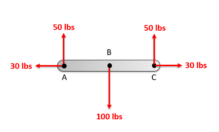
Figure \(\PageIndex{4}\): To describe all forces acting on the members of a structure, we will use a diagram to indicate the magnitude, direction, and placement of all the forces on acting on each component.
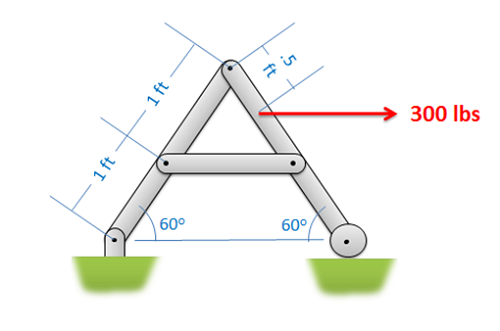
Find all the forces acting on each of the members in the structure below.
- Solution
-
Video \(\PageIndex{2}\): Worked solution to example problem \(\PageIndex{1}\), provided by Dr. Jacob Moore. YouTube source: https://youtu.be/ix2BuRGMGBs.
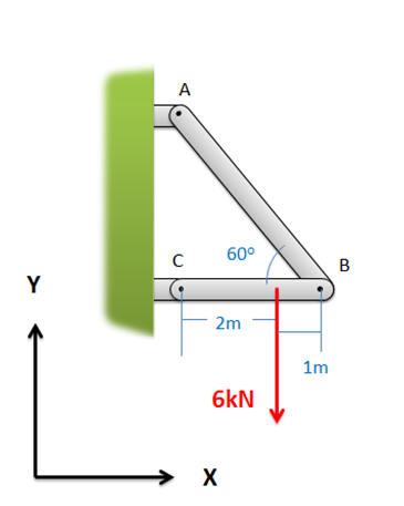
Find all the forces acting on each of the members in the structure below.
- Solution
-
Video \(\PageIndex{3}\): Worked solution to example problem \(\PageIndex{2}\), provided by Dr. Jacob Moore. YouTube source: https://youtu.be/TJjsz5Yt3Y0.
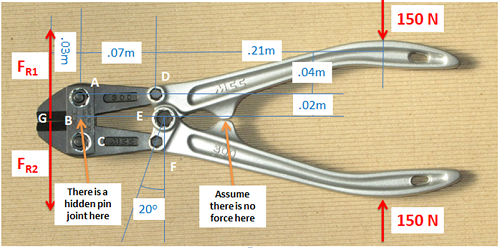
If two 150-Newton forces are exerted on the handles of the bolt cutter shown below, determine the reaction forces \((F_{R1}\) and \((F_{R2})\) exerted on the blades of the bolt cutter (this will be equal to the cutting forces exerted by the bolt cutters).
- Solution
-
Video \(\PageIndex{4}\): Worked solution to example problem \(\PageIndex{3}\), provided by Dr. Jacob Moore. YouTube source: https://youtu.be/uLsfSMzc5eQ.
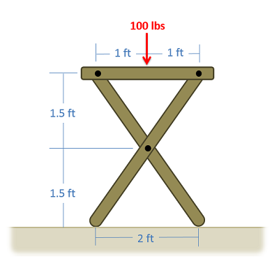
A 100-lb force is exerted on one side of a TV tray as shown below. Assuming there are no friction forces at the base, determine all forces acting on each of the three parts of the TV tray.
- Solution
-
Video \(\PageIndex{5}\): Worked solution to example problem \(\PageIndex{4}\), provided by Dr. Jacob Moore. YouTube source: https://youtu.be/qi7WNDSb43k.