
3.1: Moment of a Force about a Point (Scalar Calculation)
- Page ID
- 50579

\( \newcommand{\vecs}[1]{\overset { \scriptstyle \rightharpoonup} {\mathbf{#1}} } \)
\( \newcommand{\vecd}[1]{\overset{-\!-\!\rightharpoonup}{\vphantom{a}\smash {#1}}} \)
\( \newcommand{\dsum}{\displaystyle\sum\limits} \)
\( \newcommand{\dint}{\displaystyle\int\limits} \)
\( \newcommand{\dlim}{\displaystyle\lim\limits} \)
\( \newcommand{\id}{\mathrm{id}}\) \( \newcommand{\Span}{\mathrm{span}}\)
( \newcommand{\kernel}{\mathrm{null}\,}\) \( \newcommand{\range}{\mathrm{range}\,}\)
\( \newcommand{\RealPart}{\mathrm{Re}}\) \( \newcommand{\ImaginaryPart}{\mathrm{Im}}\)
\( \newcommand{\Argument}{\mathrm{Arg}}\) \( \newcommand{\norm}[1]{\| #1 \|}\)
\( \newcommand{\inner}[2]{\langle #1, #2 \rangle}\)
\( \newcommand{\Span}{\mathrm{span}}\)
\( \newcommand{\id}{\mathrm{id}}\)
\( \newcommand{\Span}{\mathrm{span}}\)
\( \newcommand{\kernel}{\mathrm{null}\,}\)
\( \newcommand{\range}{\mathrm{range}\,}\)
\( \newcommand{\RealPart}{\mathrm{Re}}\)
\( \newcommand{\ImaginaryPart}{\mathrm{Im}}\)
\( \newcommand{\Argument}{\mathrm{Arg}}\)
\( \newcommand{\norm}[1]{\| #1 \|}\)
\( \newcommand{\inner}[2]{\langle #1, #2 \rangle}\)
\( \newcommand{\Span}{\mathrm{span}}\) \( \newcommand{\AA}{\unicode[.8,0]{x212B}}\)
\( \newcommand{\vectorA}[1]{\vec{#1}} % arrow\)
\( \newcommand{\vectorAt}[1]{\vec{\text{#1}}} % arrow\)
\( \newcommand{\vectorB}[1]{\overset { \scriptstyle \rightharpoonup} {\mathbf{#1}} } \)
\( \newcommand{\vectorC}[1]{\textbf{#1}} \)
\( \newcommand{\vectorD}[1]{\overrightarrow{#1}} \)
\( \newcommand{\vectorDt}[1]{\overrightarrow{\text{#1}}} \)
\( \newcommand{\vectE}[1]{\overset{-\!-\!\rightharpoonup}{\vphantom{a}\smash{\mathbf {#1}}}} \)
\( \newcommand{\vecs}[1]{\overset { \scriptstyle \rightharpoonup} {\mathbf{#1}} } \)
\(\newcommand{\longvect}{\overrightarrow}\)
\( \newcommand{\vecd}[1]{\overset{-\!-\!\rightharpoonup}{\vphantom{a}\smash {#1}}} \)
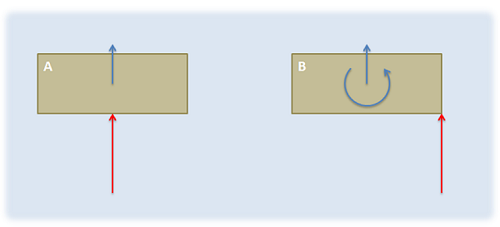
\(\newcommand{\avec}{\mathbf a}\) \(\newcommand{\bvec}{\mathbf b}\) \(\newcommand{\cvec}{\mathbf c}\) \(\newcommand{\dvec}{\mathbf d}\) \(\newcommand{\dtil}{\widetilde{\mathbf d}}\) \(\newcommand{\evec}{\mathbf e}\) \(\newcommand{\fvec}{\mathbf f}\) \(\newcommand{\nvec}{\mathbf n}\) \(\newcommand{\pvec}{\mathbf p}\) \(\newcommand{\qvec}{\mathbf q}\) \(\newcommand{\svec}{\mathbf s}\) \(\newcommand{\tvec}{\mathbf t}\) \(\newcommand{\uvec}{\mathbf u}\) \(\newcommand{\vvec}{\mathbf v}\) \(\newcommand{\wvec}{\mathbf w}\) \(\newcommand{\xvec}{\mathbf x}\) \(\newcommand{\yvec}{\mathbf y}\) \(\newcommand{\zvec}{\mathbf z}\) \(\newcommand{\rvec}{\mathbf r}\) \(\newcommand{\mvec}{\mathbf m}\) \(\newcommand{\zerovec}{\mathbf 0}\) \(\newcommand{\onevec}{\mathbf 1}\) \(\newcommand{\real}{\mathbb R}\) \(\newcommand{\twovec}[2]{\left[\begin{array}{r}#1 \\ #2 \end{array}\right]}\) \(\newcommand{\ctwovec}[2]{\left[\begin{array}{c}#1 \\ #2 \end{array}\right]}\) \(\newcommand{\threevec}[3]{\left[\begin{array}{r}#1 \\ #2 \\ #3 \end{array}\right]}\) \(\newcommand{\cthreevec}[3]{\left[\begin{array}{c}#1 \\ #2 \\ #3 \end{array}\right]}\) \(\newcommand{\fourvec}[4]{\left[\begin{array}{r}#1 \\ #2 \\ #3 \\ #4 \end{array}\right]}\) \(\newcommand{\cfourvec}[4]{\left[\begin{array}{c}#1 \\ #2 \\ #3 \\ #4 \end{array}\right]}\) \(\newcommand{\fivevec}[5]{\left[\begin{array}{r}#1 \\ #2 \\ #3 \\ #4 \\ #5 \\ \end{array}\right]}\) \(\newcommand{\cfivevec}[5]{\left[\begin{array}{c}#1 \\ #2 \\ #3 \\ #4 \\ #5 \\ \end{array}\right]}\) \(\newcommand{\mattwo}[4]{\left[\begin{array}{rr}#1 \amp #2 \\ #3 \amp #4 \\ \end{array}\right]}\) \(\newcommand{\laspan}[1]{\text{Span}\{#1\}}\) \(\newcommand{\bcal}{\cal B}\) \(\newcommand{\ccal}{\cal C}\) \(\newcommand{\scal}{\cal S}\) \(\newcommand{\wcal}{\cal W}\) \(\newcommand{\ecal}{\cal E}\) \(\newcommand{\coords}[2]{\left\{#1\right\}_{#2}}\) \(\newcommand{\gray}[1]{\color{gray}{#1}}\) \(\newcommand{\lgray}[1]{\color{lightgray}{#1}}\) \(\newcommand{\rank}{\operatorname{rank}}\) \(\newcommand{\row}{\text{Row}}\) \(\newcommand{\col}{\text{Col}}\) \(\renewcommand{\row}{\text{Row}}\) \(\newcommand{\nul}{\text{Nul}}\) \(\newcommand{\var}{\text{Var}}\) \(\newcommand{\corr}{\text{corr}}\) \(\newcommand{\len}[1]{\left|#1\right|}\) \(\newcommand{\bbar}{\overline{\bvec}}\) \(\newcommand{\bhat}{\widehat{\bvec}}\) \(\newcommand{\bperp}{\bvec^\perp}\) \(\newcommand{\xhat}{\widehat{\xvec}}\) \(\newcommand{\vhat}{\widehat{\vvec}}\) \(\newcommand{\uhat}{\widehat{\uvec}}\) \(\newcommand{\what}{\widehat{\wvec}}\) \(\newcommand{\Sighat}{\widehat{\Sigma}}\) \(\newcommand{\lt}{<}\) \(\newcommand{\gt}{>}\) \(\newcommand{\amp}{&}\) \(\definecolor{fillinmathshade}{gray}{0.9}\)The moment of a force is the tendency of some forces to cause rotation. Any easy way to visualize the concept is set a box on smooth surface. If you were to apply a force to the center of the box, it would simply slide across the surface without rotating. If you were instead to push on one side of the box, it will start rotating as it moves. Even though the forces have the same magnitude and the same direction, they cause different reactions. This is because the off-center force has a different point of application, and exerts a moment about the center of the box, whereas the force on the center of the box does not exert a moment about the box's center point.
Just like forces, moments have a magnitude (the degree of rotation it would cause) and a direction (the axis the body would rotate about). Determining the magnitude and direction of these moments about a given point is an important step in the analysis of rigid body systems (bodies that are both rigid and not experiencing concurrent forces). The scalar method below is the easiest way to do this in simple two-dimensional problems, while the alternative vector methods, which will be covered later, work best for more complex three-dimensional systems.
The Scalar Method in 2 Dimensions
In discussing how to calculate the moment of a force about a point via scalar quantities, we will begin with the example of a force on a simple lever as shown below. In this simple lever there is a force on the end of the lever, distance \(d\) away from the center of rotation for the lever (point A) where the force has a magnitude \(F\).
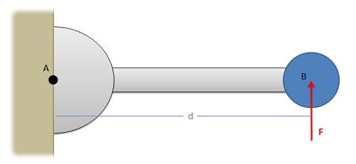
When using scalar quantities, the magnitude of the moment will be equal to the perpendicular distance between the line of action of the force and the point we are taking the moment about. \[ M \, = \, F * d \]
To determine the sign of the moment, we determine what type of rotation the force would cause. In this case, we can see that the force would cause the lever to rotate counterclockwise about point A. Counterclockwise rotations are caused by positive moments while clockwise rotations are caused by negative moments.
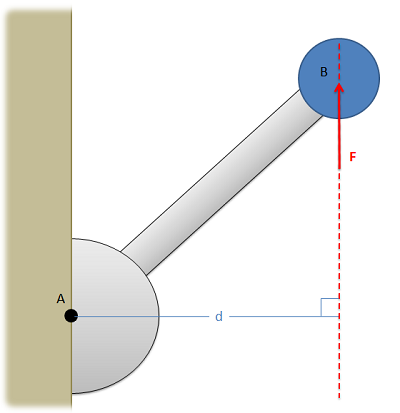
Another important factor to remember is that the value \(d\) is the perpendicular distance from the force to the point we are taking the moment about. We could measure the distance from point A to the head of the force vector, or the tail of the force vector, or really any point along the line of action of force \(F\). The distance we need to use for the scalar moment calculation, however, is the shortest distance between the point and the line of action of the force. This will always be a line perpendicular to the line of action of the force, going to the point about which we are taking the moment.
The Scalar Model in 3 Dimensions
For three-dimensional scalar calculations, we will still find the magnitude of the moment in the same way, multiplying the magnitude of the force by the perpendicular distance between the point and the line of action of the force. This perpendicular distance again is the minimum distance between the point and the line of action of the force. In some cases, finding this distance may be very difficult.
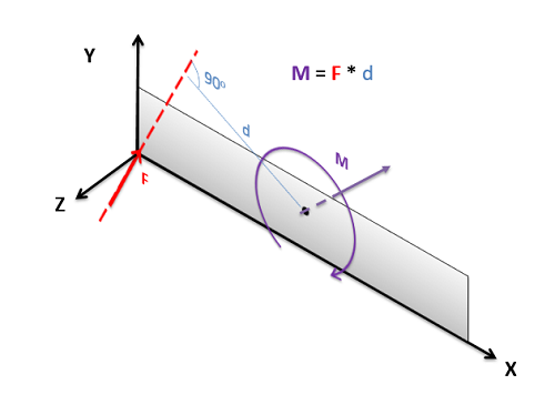
Another difficult factor in three dimensional scalar problems is finding the axis of rotation, as this is now more complex that just "clockwise or counterclockwise". The axis of rotation will be a line traveling though the point about which we are taking the moment, and perpendicular to both the force vector and the perpendicular displacement vector (the vector going from the point about which the moment was taken to the point of application of the force). While this is possible in any situation, it becomes very difficult if the force or displacement vectors do not lie in one of the three coordinate directions.
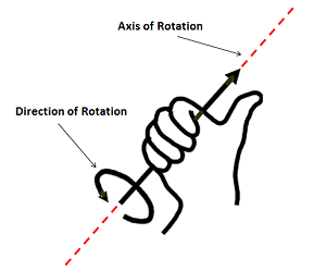
To further find the direction of the moment vector (which will act along the established line for axis of rotation), we will use the right-hand rule in a modified form. Wrap the fingers of your right hand around the axis of rotation line with your fingertips curling in the direction the body would rotate. If you do this, your thumb should point out along the line in the direction of the moment vector. This is an important last step, because we can rotate clockwise or counterclockwise in about any given axis of rotation. With the final moment vector, we known not only the axis of rotation, but which way the body would rotate about that axis.
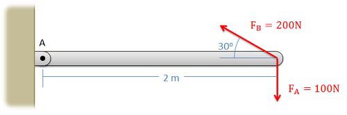
What is the moment that Force A exerts about point A? What is the moment that Force B exerts about Point A?
- Solution
-
Video \(\PageIndex{7}\): Worked solution to example problem \(\PageIndex{1}\), provided by Dr. Jacob Moore. YouTube source: https://youtu.be/E9Xq1fXdcyE.
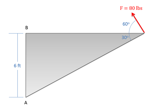
What is the moment that this force exerts about point A? What is the moment this force exerts about point B?
- Solution
-
Video \(\PageIndex{3}\): Worked solution to example problem \(\PageIndex{2}\), provided by Dr. Jacob Moore. YouTube source: https://youtu.be/9nb2q3EN5gs.
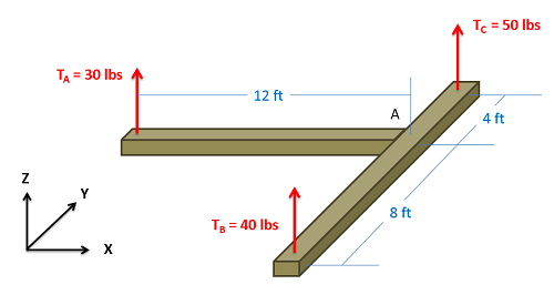
What are the moments that each of the three tension forces exert about point A (the point where the beams come together)?
- Solution
-
Video \(\PageIndex{4}\): Worked solution to example problem \(\PageIndex{3}\), provided by Dr. Jacob Moore. YouTube source: https://youtu.be/2W9-K2KsTMU.