
3.7: Chapter 3 Homework Problems
- Page ID
- 52384

\( \newcommand{\vecs}[1]{\overset { \scriptstyle \rightharpoonup} {\mathbf{#1}} } \)
\( \newcommand{\vecd}[1]{\overset{-\!-\!\rightharpoonup}{\vphantom{a}\smash {#1}}} \)
\( \newcommand{\id}{\mathrm{id}}\) \( \newcommand{\Span}{\mathrm{span}}\)
( \newcommand{\kernel}{\mathrm{null}\,}\) \( \newcommand{\range}{\mathrm{range}\,}\)
\( \newcommand{\RealPart}{\mathrm{Re}}\) \( \newcommand{\ImaginaryPart}{\mathrm{Im}}\)
\( \newcommand{\Argument}{\mathrm{Arg}}\) \( \newcommand{\norm}[1]{\| #1 \|}\)
\( \newcommand{\inner}[2]{\langle #1, #2 \rangle}\)
\( \newcommand{\Span}{\mathrm{span}}\)
\( \newcommand{\id}{\mathrm{id}}\)
\( \newcommand{\Span}{\mathrm{span}}\)
\( \newcommand{\kernel}{\mathrm{null}\,}\)
\( \newcommand{\range}{\mathrm{range}\,}\)
\( \newcommand{\RealPart}{\mathrm{Re}}\)
\( \newcommand{\ImaginaryPart}{\mathrm{Im}}\)
\( \newcommand{\Argument}{\mathrm{Arg}}\)
\( \newcommand{\norm}[1]{\| #1 \|}\)
\( \newcommand{\inner}[2]{\langle #1, #2 \rangle}\)
\( \newcommand{\Span}{\mathrm{span}}\) \( \newcommand{\AA}{\unicode[.8,0]{x212B}}\)
\( \newcommand{\vectorA}[1]{\vec{#1}} % arrow\)
\( \newcommand{\vectorAt}[1]{\vec{\text{#1}}} % arrow\)
\( \newcommand{\vectorB}[1]{\overset { \scriptstyle \rightharpoonup} {\mathbf{#1}} } \)
\( \newcommand{\vectorC}[1]{\textbf{#1}} \)
\( \newcommand{\vectorD}[1]{\overrightarrow{#1}} \)
\( \newcommand{\vectorDt}[1]{\overrightarrow{\text{#1}}} \)
\( \newcommand{\vectE}[1]{\overset{-\!-\!\rightharpoonup}{\vphantom{a}\smash{\mathbf {#1}}}} \)
\( \newcommand{\vecs}[1]{\overset { \scriptstyle \rightharpoonup} {\mathbf{#1}} } \)
\( \newcommand{\vecd}[1]{\overset{-\!-\!\rightharpoonup}{\vphantom{a}\smash {#1}}} \)
\(\newcommand{\avec}{\mathbf a}\) \(\newcommand{\bvec}{\mathbf b}\) \(\newcommand{\cvec}{\mathbf c}\) \(\newcommand{\dvec}{\mathbf d}\) \(\newcommand{\dtil}{\widetilde{\mathbf d}}\) \(\newcommand{\evec}{\mathbf e}\) \(\newcommand{\fvec}{\mathbf f}\) \(\newcommand{\nvec}{\mathbf n}\) \(\newcommand{\pvec}{\mathbf p}\) \(\newcommand{\qvec}{\mathbf q}\) \(\newcommand{\svec}{\mathbf s}\) \(\newcommand{\tvec}{\mathbf t}\) \(\newcommand{\uvec}{\mathbf u}\) \(\newcommand{\vvec}{\mathbf v}\) \(\newcommand{\wvec}{\mathbf w}\) \(\newcommand{\xvec}{\mathbf x}\) \(\newcommand{\yvec}{\mathbf y}\) \(\newcommand{\zvec}{\mathbf z}\) \(\newcommand{\rvec}{\mathbf r}\) \(\newcommand{\mvec}{\mathbf m}\) \(\newcommand{\zerovec}{\mathbf 0}\) \(\newcommand{\onevec}{\mathbf 1}\) \(\newcommand{\real}{\mathbb R}\) \(\newcommand{\twovec}[2]{\left[\begin{array}{r}#1 \\ #2 \end{array}\right]}\) \(\newcommand{\ctwovec}[2]{\left[\begin{array}{c}#1 \\ #2 \end{array}\right]}\) \(\newcommand{\threevec}[3]{\left[\begin{array}{r}#1 \\ #2 \\ #3 \end{array}\right]}\) \(\newcommand{\cthreevec}[3]{\left[\begin{array}{c}#1 \\ #2 \\ #3 \end{array}\right]}\) \(\newcommand{\fourvec}[4]{\left[\begin{array}{r}#1 \\ #2 \\ #3 \\ #4 \end{array}\right]}\) \(\newcommand{\cfourvec}[4]{\left[\begin{array}{c}#1 \\ #2 \\ #3 \\ #4 \end{array}\right]}\) \(\newcommand{\fivevec}[5]{\left[\begin{array}{r}#1 \\ #2 \\ #3 \\ #4 \\ #5 \\ \end{array}\right]}\) \(\newcommand{\cfivevec}[5]{\left[\begin{array}{c}#1 \\ #2 \\ #3 \\ #4 \\ #5 \\ \end{array}\right]}\) \(\newcommand{\mattwo}[4]{\left[\begin{array}{rr}#1 \amp #2 \\ #3 \amp #4 \\ \end{array}\right]}\) \(\newcommand{\laspan}[1]{\text{Span}\{#1\}}\) \(\newcommand{\bcal}{\cal B}\) \(\newcommand{\ccal}{\cal C}\) \(\newcommand{\scal}{\cal S}\) \(\newcommand{\wcal}{\cal W}\) \(\newcommand{\ecal}{\cal E}\) \(\newcommand{\coords}[2]{\left\{#1\right\}_{#2}}\) \(\newcommand{\gray}[1]{\color{gray}{#1}}\) \(\newcommand{\lgray}[1]{\color{lightgray}{#1}}\) \(\newcommand{\rank}{\operatorname{rank}}\) \(\newcommand{\row}{\text{Row}}\) \(\newcommand{\col}{\text{Col}}\) \(\renewcommand{\row}{\text{Row}}\) \(\newcommand{\nul}{\text{Nul}}\) \(\newcommand{\var}{\text{Var}}\) \(\newcommand{\corr}{\text{corr}}\) \(\newcommand{\len}[1]{\left|#1\right|}\) \(\newcommand{\bbar}{\overline{\bvec}}\) \(\newcommand{\bhat}{\widehat{\bvec}}\) \(\newcommand{\bperp}{\bvec^\perp}\) \(\newcommand{\xhat}{\widehat{\xvec}}\) \(\newcommand{\vhat}{\widehat{\vvec}}\) \(\newcommand{\uhat}{\widehat{\uvec}}\) \(\newcommand{\what}{\widehat{\wvec}}\) \(\newcommand{\Sighat}{\widehat{\Sigma}}\) \(\newcommand{\lt}{<}\) \(\newcommand{\gt}{>}\) \(\newcommand{\amp}{&}\) \(\definecolor{fillinmathshade}{gray}{0.9}\)An 18-inch shelf is supported by a pin joint at point A, and a cable at point B. The shelf itself has a weight of 60 lbs. If we want the net moment about point A to be zero, what should the tension in the cable be?
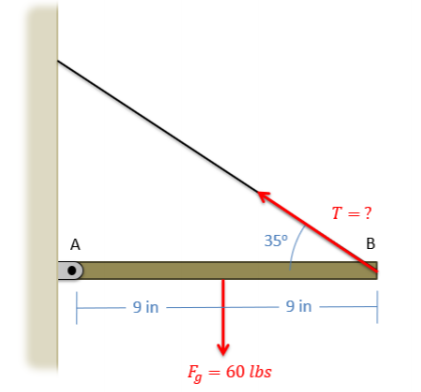.png?revision=1)
- Solution
-
\(T = 52.30 \, lbs\)
What is the moment the force shown below exerts about Point A? About Point B?
Hint: use Varginon's Theorem.
.png?revision=1)
- Solution
-
\(M_A = 10.88 \, kNm \)
\(M_B = 21.02 \, kNm\)
You are attempting to rotate a heavy table about the base of one leg at point O and are going to exert a 100-lb force at the opposite end. Person A recommends pulling straight up, while person B recommends pulling up at 30° from vertical. What would be the moment about point O, in inch-pounds, in either case?
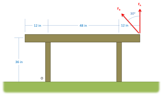.png?revision=1)
- Solution
-
\(M_{AO} = 6000 \, \text{in-lbs} \)
\(M_{BO} = 6996.15 \, \text{in-lbs}\)
Determine the moment vectors that each of the three tension forces in the diagram below exerts about the origin point O. Provide the answers in vector form with units.
.png?revision=1)
- Solution
-
\(M_{AO} = [0, \, -400, \, 0] \, Nm\)
\(M_{BO} = [-300, \, 0, \, 0] \, Nm\)
\( M_{CO} = [300, \, 0, \, 0] Nm\)
You exert a 50-lb force on the side of a fridge as shown below. Assuming the fridge is sitting on a rough surface and not moving, what is the magnitude of the moment exerted by the couple consisting of the pushing force and the friction force?
.png?revision=1)
- Solution
-
\(M = -100 \text{ft-lbs}\)
A space station consists of a large ring that spins in order to provide an artificial gravity for the astronauts in the station. To start the station spinning, a pair of thrusters is attached to the outside of the ring, each pointing in opposite directions as shown below.
a) If we want to exert a 10 kN-m moment with the thrusters, and the ring has a diameter of 45 meters, what thrust force should each thruster produce?
b) If we were to use the same thrusters on a 60-meter diameter ring, what moment would they exert?
.png?revision=1)
- Solution
-
a) \(F_{thruster} = 222.22 \, N\)
b) \(M_{thruster} = 13.33 \, kNm\)
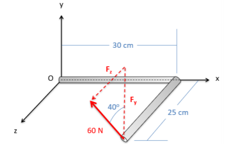
A 60-N force is applied in the \(yz\) plane, 40° from the \(y\) direction, on an L-shaped bar as shown below.
a) What is the moment vector this force exerts about point O?
b) What is the overall magnitude of the moment about point O?
.png?revision=1)
- Solution
-
\(M_O = [-11.49, \, -11.57, \, 13.79] \, Nm\)
\(|M| = 21.36 \, Nm\)
What is the moment that the force shown in the diagram exerts about point O? About the axis of the cylindrical shaft (the \(y\)-axis)?
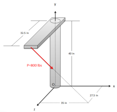.png?revision=1)
- Solution
-
\(M_O = [16484, \, 17046, \, -20979] \, in-lbs\)
\(M_y = 17046 \, in-lbs\)
The diving board shown below is supported by a pin joint at A and frictionless support at B. A 150-lb diver is standing at the end of the board. Determine the reaction forces acting on the diving board at points A and B.
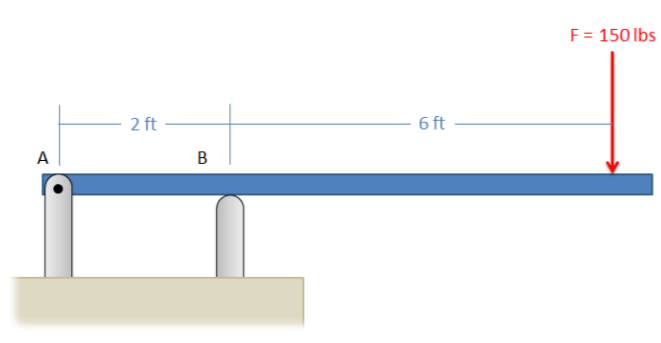.png?revision=1)
- Solution
-
\(F_{AX} = 0\)
\(F_{AY} = -450 \, lbs\)
\(F_{BY} = 600 \, lbs\)
A simplified crane is shown lifting a 400-kg load. The crane is supported by a pin joint at A, and a cable at B. Assuming the crane arm is in equilibrium, what are the reaction forces at A and the tension at B?
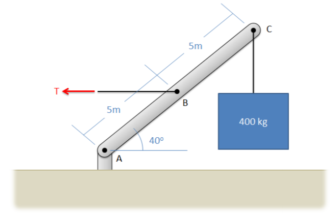.png?revision=1)
- Solution
-
\(F_{AX} = 9352.9 \, N\)
\(F_{AY} = 3924 \, N\)
\(T_{B} = 9352.9 \, N\)
An 8-foot ladder sits propped up against a wall at a 60-degree angle as shown below. It has a weight of 50 lbs acting at its center point and supports a 120-lb woman 6 feet from the bottom. Assume that friction acts at the bottom of the ladder, but not the top. What are the normal forces acting at the bottom and top of the ladder, and what is the friction force acting at the bottom of the ladder?
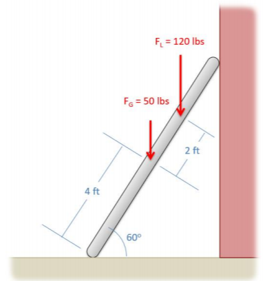.png?revision=1)
- Solution
-
\(F_{N \, Top} = 66.4 \, lbs\)
\(F_{N \, Bottom} = 170 \, lbs\)
\(F_f = 66.4 lbs\)
An SUV with a weight of 4200 lbs and a center of mass located as shown below is parked pointed downhill on a 10-degree incline. The parking is engaged, locking up the back wheels but not the front wheels. What is the expected normal force at the front wheels, the expected normal force at the back wheels, and the expected friction force at the back wheels assuming the SUV does not slip?
.png?revision=1)
- Solution
-
\(F_f = 729.3 \, lbs\)
\(F_{N \, front} = 3000.6 \, lbs\)
\(F_{N \, back} = 1135.6 \, lbs\)
A cart with a mass of 3500 kg sits on an inclined surface as shown below. Determine the reaction forces acting on each wheel of the cart as well as the tension in the cable supporting the cart.
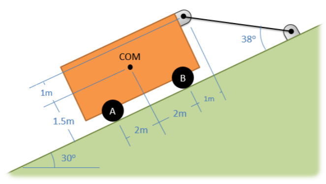.png?revision=1)
- Solution
-
\(T = 21786 \, N\)
\(F_A = 7222 \, N; \, F_B = 35925 \, N\)
The lighting rig above a stage consists of two 100-lb, uniform beams joined together in a T as shown below (assume the weight acts in the center of each beam). The rig is supported by three cables at A, B, and C. Determine the tension in each of the three cables.
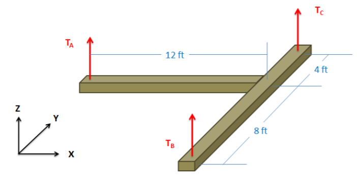.png?revision=1)
- Solution
-
\(T_A = 50 \, lbs; \, \, T_B = 66.7 \, lbs; \, T_C = 83.3 \, lbs\)
A 9-meter-long pole with a mass of 100 kg is suspended horizontally, 4 meters from the ceiling with three cables as shown below. Assuming the center of mass of the pole is at the center point of the pole, what is the expected tension in each of the three cables?
.png?revision=1)
- Solution
-
\(T_A = 357.66 \, N; \, T_B = 357.66 \, N; \, T_C = 408.75 \, N\)