

Chapter 3: Strain
- Page ID
- 145517

\( \newcommand{\vecs}[1]{\overset { \scriptstyle \rightharpoonup} {\mathbf{#1}} } \)
\( \newcommand{\vecd}[1]{\overset{-\!-\!\rightharpoonup}{\vphantom{a}\smash {#1}}} \)
\( \newcommand{\dsum}{\displaystyle\sum\limits} \)
\( \newcommand{\dint}{\displaystyle\int\limits} \)
\( \newcommand{\dlim}{\displaystyle\lim\limits} \)
\( \newcommand{\id}{\mathrm{id}}\) \( \newcommand{\Span}{\mathrm{span}}\)
( \newcommand{\kernel}{\mathrm{null}\,}\) \( \newcommand{\range}{\mathrm{range}\,}\)
\( \newcommand{\RealPart}{\mathrm{Re}}\) \( \newcommand{\ImaginaryPart}{\mathrm{Im}}\)
\( \newcommand{\Argument}{\mathrm{Arg}}\) \( \newcommand{\norm}[1]{\| #1 \|}\)
\( \newcommand{\inner}[2]{\langle #1, #2 \rangle}\)
\( \newcommand{\Span}{\mathrm{span}}\)
\( \newcommand{\id}{\mathrm{id}}\)
\( \newcommand{\Span}{\mathrm{span}}\)
\( \newcommand{\kernel}{\mathrm{null}\,}\)
\( \newcommand{\range}{\mathrm{range}\,}\)
\( \newcommand{\RealPart}{\mathrm{Re}}\)
\( \newcommand{\ImaginaryPart}{\mathrm{Im}}\)
\( \newcommand{\Argument}{\mathrm{Arg}}\)
\( \newcommand{\norm}[1]{\| #1 \|}\)
\( \newcommand{\inner}[2]{\langle #1, #2 \rangle}\)
\( \newcommand{\Span}{\mathrm{span}}\) \( \newcommand{\AA}{\unicode[.8,0]{x212B}}\)
\( \newcommand{\vectorA}[1]{\vec{#1}} % arrow\)
\( \newcommand{\vectorAt}[1]{\vec{\text{#1}}} % arrow\)
\( \newcommand{\vectorB}[1]{\overset { \scriptstyle \rightharpoonup} {\mathbf{#1}} } \)
\( \newcommand{\vectorC}[1]{\textbf{#1}} \)
\( \newcommand{\vectorD}[1]{\overrightarrow{#1}} \)
\( \newcommand{\vectorDt}[1]{\overrightarrow{\text{#1}}} \)
\( \newcommand{\vectE}[1]{\overset{-\!-\!\rightharpoonup}{\vphantom{a}\smash{\mathbf {#1}}}} \)
\( \newcommand{\vecs}[1]{\overset { \scriptstyle \rightharpoonup} {\mathbf{#1}} } \)
\(\newcommand{\longvect}{\overrightarrow}\)
\( \newcommand{\vecd}[1]{\overset{-\!-\!\rightharpoonup}{\vphantom{a}\smash {#1}}} \)
\(\newcommand{\ket}[1]{\left| #1 \right>}\)
\(\newcommand{\bra}[1]{\left< #1 \right|}\)
\(\newcommand{\braket}[2]{\left< #1 \vphantom{#2} \right| \left. #2 \vphantom{#1} \right>}\)
\(\newcommand{\braopket}[3]{\left< #1 \vphantom{#2}\vphantom{#3} \right| #2 \vphantom{#1}\vphantom{#3} \left| #3 \vphantom{#1}\vphantom{#2} \right>}\)
\(\newcommand{\qmvec}[1]{\mathbf{\vec{#1}}}\)
\(\newcommand{\op}[1]{\hat{\mathbf{#1}}}\)
\(\newcommand{\expect}[1]{\langle #1 \rangle}\)
\(\newcommand{\dfn}[1]{\emph{\textbf{#1}}}\)
Learning Objectives
-
Define strain
-
Explain the difference between normal strain and shear strain
-
Calculate normal and shear strains due to applied loads
Chapter 2 showed how to calculate normal and shear stresses with respect to a plane of interest, such as a cross-sectional area or an inclined plane. If stresses increase too much, the object will break, so it is important that engineers design structures and machines such that the stresses stay within certain acceptable limits. It is also important that objects do not deform so much that they are no longer fit for their original purpose. Strain is a measure of the intensity of a deformation—that is, the deformation per unit length.
Imagine two points on a body, A and B, separated by some distance L (Figure 3.1). In statics (and dynamics), it is assumed that objects are rigid and do not deform when subjected to forces. In reality, forces will cause an object to deform and consequently its dimensions will change. As points A and B move with the object, the distance between them will change to some new distance L’.

Figure 3.1: Nonrigid bodies will deform under load, and the distance between any two points A and B will change as the body deforms.
These deformations may be very large relative to the size of the object (e.g., a rubber band), or they may be relatively small (e.g., structural members), but there will always be some amount of deformation because no material is infinitely stiff, as we will learn in Chapter 4. Engineers must design structures and machines such that these deformations are not excessively large for the intended application.
This chapter introduces two types of strain. Section 3.1 covers normal strain, which like normal stress occurs when objects are subjected to axial loads. Section 3.2 covers shear strain, which like shear stress occurs when objects are subjected to shear loads.
3.1 Normal Strain
A simple example of normal strain is the deformation of a bar subjected to an axial load. Consider a bar of length L subjected to a tensile axial load P as shown in Figure 3.2. The load creates normal stress in the rod and also causes the rod to elongate by an amount ΔL.

Figure 3.2: Axial loads cause a change in length that depends partly on the original length of the object.
If the same load were applied to a longer rod of length 2L with the same cross-sectional area, the longer rod would elongate by an amount 2ΔL. The deformation depends on the original length of the rod in this case, but the strain doesn't. Strain is a measure that normalizes the change in length by the original length. Normal strain is represented by the Greek letter epsilon (e) and is defined as
(3.1)
where
This is a normal strain because it occurs under axial load and is associated with a change in the object's length. Since normal strain is defined by dividing one length by another, it is a dimensionless quantity—that is, it has no units. It is nonetheless fairly common to include units of mm/mm or in./in.
For example, if the rod was initially 5 m long and it elongated by 12 mm, the normal strain can be calculated as
Note that the units used for ΔL and L must be the same, but whether they are expressed in mm or m doesn't matter. Using meters instead yields the same answer.
In fact, because the normal strain is dimensionless, its magnitude is the same in any system of units.
Because strains tend to be quite small in many engineering applications, they are sometimes expressed with a prefix to eliminate the leading zeros. For example, a strain of 0.0024 may be expressed as 2.4 mm/m or 2,400 µm/m or simply 2,400 µ. Strains may also be expressed as a percentage, which can be found simply by multiplying the strain by 100 percent. The following strains are all equivalent:
Here we will use the sign convention that we defined for normal stress. Tensile forces and stresses, associated with elongation of the bar and tensile normal strain, are positive. Compressive forces and stresses, associated with shortening of the bar and compressive normal strain, are negative (Figure 3.3).

Figure 3.3: (A) Objects in tension will elongate. By convention, tension and elongation are positive. (B) Objects in compression will shorten. By convention, compression and shortening are negative.
See Example 3.1 for a problem involving a bar experiencing both tension and compression. Example 3.2 involves strain in two parallel cables.
Example 3.1
The bar is subjected to forces F1 = 30 kips and F2 = 10 kips as shown. Segment AB is originally 10 in. in length and segment BC is originally 15 in. in length. As a result of the applied forces, the normal strain in segment AB is -0.03 in./in. and the strain in segment BC is 0.045 in./in.
-
Determine the change in length of each segment.
-
Determine the average strain for the entire bar.

Solution
Using for each segment, rearrange to calculate the change in length of each segment.
To find the average strain for the entire bar, first find the overall change in length for the entire bar.
Overall the bar elongates by 0.375 in. The original length of the bar was 25 in. We can now determine the strain for the entire bar.
Example 3.2
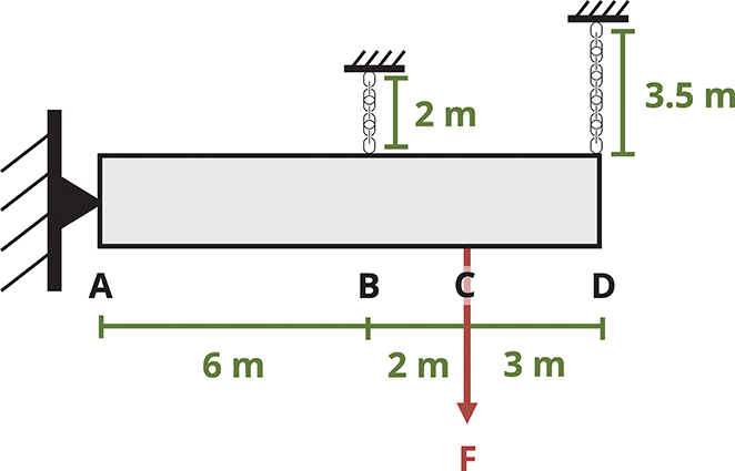
Rigid bar ABCD is supported by a pin at A and cables at B and D. After load F is applied, the strain in cable D is 2,300 µm/m.
Determine the strain in cable B.
Solution
Consider the deflected position of rigid bar ABCD. Now calculate the change in length of cable D.

Point D will deflect downward by 8.05 mm.
Use similar triangles to find the deflection of point B.
Cable B elongates by 4.39 mm. Use this to determine the strain in cable B. Be careful to be consistent with units. Use either ΔL = 4.39 mm and L = 2,000 mm or ΔL = 0.00439 m and L = 2 m.
Step-by-Step: Normal Strain
-
Determine the change in length of the object.
-
Calculate the normal strain,
3.2 Shear Strain
Consider a small square element that may be part of a body such as that shown in Figure 3.1. Just as the distance between points changes as the body deforms, so the shape of this square element also changes. The corners of the square element initially form right angles. As the body deforms and the points move with the object, the element's shape changes and the corners no longer form right angles (Figure 3.4). There is a small horizontal displacement of amount Δx.
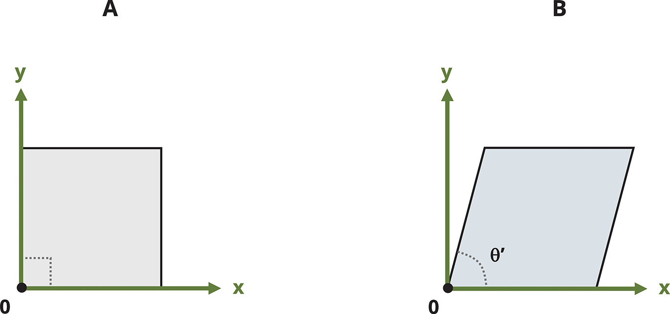
Figure 3.4: (A) The undeformed element is initially square, with right-angled corners. (B) As the body deforms, the square element skews and the corners are no longer right angles.
Shear strain is denoted by the Greek letter gamma () and, like normal strain, is a dimensionless quantity. Recall that normal strain was defined in Equation 3.1 as the change in length of the object divided by its original length. Shear strain is similarly defined, but the deformation is perpendicular to the side length instead of parallel to it (Figure 3.5). If the element has side length L and displacement Δx, the shear strain is defined as

Figure 3.5: As the element deforms under shear, the shear strain at corner O is defined as .
(3.2)
where
For small deformations, the shear strain is commonly approximated as a change in angle. Specifically, provided we start with right-angled corners, shear strain can be approximated as the original angle (before deformation) minus the new angle (after deformation). Regardless of the shape of the body, a square element can always be defined such that the original angle is always a right angle. After deformation, the new angle between these three points is θ’. By convention, shear strain is represented in radians. Thus the original right angle is represented as radians and the shear strain as
where
-
= Shear strain [rad]
-
= Original angle [rad]
-
θ’ = New angle [rad]
Finding angle directly, without first finding angle θ’, is often an easier approach. Consider the deformed element in Figure 3.5. If the element has side length L and horizontal displacement Δx, the angle γ can be found from . For small angles where (when calculated in radians), this is approximately , as defined earlier.
Note that because we always subtract the new angle from the original angle, if the angle increases, the result is a negative shear strain, and if the angle decreases, it is a positive shear strain (Figure 3.6).

Figure 3.6: (A) If the new angle θ’ is larger than radians, the shear strain is negative. (B) If the new angle θ’ is smaller than radians, the shear strain is positive.
See Example 3.3 and Example 3.4 to practice calculating shear strain.
Example 3.3
A thin rectangular plate has a base of 300 mm and a height of 500 mm. Initially corners A, B, C, and D are all right angles. The plate is subjected to a shear force V, which deforms the plate into the dotted lines shown. Corner D moves straight downward by 5 mm.
Determine the shear strain at corner A.

Solution
We could calculate the new angle at corner A as .

Angle α can be found, since there is a triangle of base 300 mm and height 5 mm.
Then
Now the shear strain can be calculated.
Notice that this is just the negative of angle a. Since the shear strain is the change in angle and α represents the increase of the angle, we could simply have said that angle α is the shear strain. As defined in Section 3.2, the shear strain is negative because the angle is increasing.
Example 3.4
A thin triangular plate ABC has a base of 8 in. and a height of 20 in. Corner A is initially a right angle. When subjected to a shear load, the plate deforms as shown. Corner B moves 0.1 in. to the right and corner C moves 0.06 in. downward.
Determine the shear strain at corner A.

Solution
The angle at A will decrease by angle α and increase by angle β. Start by finding these angles.

The new angle at A is
With the new angle known, we can calculate the shear strain.
Note that the shear strain can be calculated more directly. Given that shear strain is just the change in angle, we could have said that the angle at A decreases by angle α and increases by angle β.
Recall that shear strain is positive if the angle decreases and negative if the angle increases. The change in angle at A, and thus the shear strain, could be calculated as
Step-by-Step: Shear Strain
-
Begin with a corner that forms a right angle ( rads) prior to deformation.
-
After deformation, determine the new angle () at this corner.
-
Determine the shear strain,
Summary
Key Takeaways
Objects may experience a change in length. If, for example, the axial load is tensile, the length will increase. If the load is compressive, the length will decrease.
Normal strain is defined as the change in length divided by the original length. Although strain has no units, it is commonly written with units of mm/mm or in./in. or similar. Normal strain is positive if the length increases and negative if the length decreases.
Objects subjected to shear loads experience a change in angle. Shear strain is defined as this change in angle, expressed as original angle minus new angle, where the original angle is always a right angle. Shear strains are positive if the angle decreases and negative if the angle increases.
Shear strains are expressed in radians, not degrees, and so the original angle is always defined as radians.
Key Equations
Normal strain:
Shear strain:
References
Figures
All figures in this chapter were created by Kindred Grey in 2025 and released under a CC BY license.