6.2: Deflections of Circular Plates
- Page ID
- 21505

The governing equation (6.1.9) still holds but the Laplace operator \(\nabla^2\) should now be defined in the polar coordinate system \((r, \theta)\)
\[\nabla^2w = \frac{\partial^2w}{\partial r^2} + \frac{1}{r}\frac{\partial w}{\partial r} + \frac{1}{r^2}\frac{\partial^2w}{\partial \theta^2} \label{7.15}\]
In the circular plate subjected to axi-symmetric loading \(p = p(r)\), the third term in Equation \ref{7.15} vanishes and the Laplace operator can be put in the form
\[\nabla^2w = \frac{\partial^2w}{\partial r^2} + \frac{1}{r}\frac{\partial w}{\partial r} = \frac{1}{r}\frac{d}{dr} \left(r\frac{dw}{dr}\right) \]
With the above definition, the plate bending equation becomes
\[\frac{1}{r}\frac{d}{dr}\left\{r\frac{d}{dr}\left[\frac{1}{r}\frac{d}{dr}\left(r\frac{dw}{dr}\right)\right]\right\} = \frac{p(r)}{D}\]
and the solution is obtained by four successive integration
\[w(r) = \int \frac{1}{r} \int r \int \frac{1}{r} \int \frac{rp(r)}{D} dr dr dr dr \]
Assuming a uniform loading of the intensity \(p_o\), the above integration can be easily performed to give
\[w(r) = C_1 \ln r + C_2 r^2 + C_3r^2 \ln r + C_4 + \frac{p_or^4}{64D} \label{7.19}\]
As an illustration, consider clamped boundary conditions:
\[\text{at } r = R \quad w = 0 \text{ and } \frac{dw}{dr} = 0 \]
\[\text{at } r = 0 \quad \frac{dw}{dr} = 0 \text{ and } \bar{V}_r = 0 \]
where the shear force (per unit length), acting on a plate element at a distance \(r\) is
\[V_r = − \frac{1}{2\pi r} \int_{0}^{r} p_o 2\pi r dr = − \frac{p_o r}{2} \]
The two terms in Equation \ref{7.19} involving logarithms tend to infinity at \(r \rightarrow 0\). Therefore, in order for the solution to give finite values of deflections at the center, \(C_1 = C_3 = 0\). Now, the expression for the slope is
\[\frac{dw}{dr} = 2C_2r + \frac{p_or^3}{18D} \]
Now, the boundary conditions at \(r = 0\) are satisfied identically. From two boundary conditions at \(r = R\), one finds the integration constants
\[C_2 = − \frac{p_oR^2}{32D}, \quad C_4 = \frac{p_oR^4}{64D} \]
The final form of the solution for the plate deflection is
\[w(r) = \frac{p_oR^4}{64D} \left[1 − \left(\frac{r}{R}\right)^2 \right]^2 \label{7.24}\]
For comparison, the solution for the simply supported plate will be derived. The boundary conditions are mixed so the moment-curvature relation must be used
\[M_r = D \left[ \frac{d^2w}{dr^2} + \nu \frac{1}{r}\frac{dw}{dr}\right] \label{7.25a}\]
\[M_{\theta} = D \left[ \frac{1}{r}\frac{dw}{dr} + \nu \frac{d^2w}{dr^2}\right] \label{7.25b}\]
where the definition of moments in the cylindrical coordinate system was used. At the plate edge
\[w = 0 \text{ and } M_r = 0 \quad \text{ at } r = R \label{7.26}\]
From Equations \ref{7.19}, \ref{7.25a} - \ref{7.25b} and \ref{7.26}, the system of two algebraic equations for \(C_2\) and \(C_4\) is obtained, where solution is
\[C_2 = − \frac{p_oR^2}{32D}\frac{3 + \nu}{1 + \nu}, \quad C_4 = \frac{p_oR^4}{64D}\frac{5 + \nu}{1 + \nu}\]
The formula for the plate deflection is
\[w(r) = \frac{pR^4}{64D}\left[ \left( \frac{r}{R}\right)^4 - 2\left(\frac{r}{R}\right)^2 \frac{3 + \nu}{1 + \nu} + \frac{5 + \nu}{1 + \nu}\right] \]
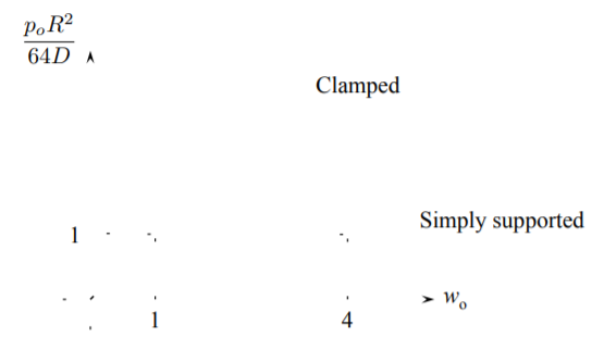
The ratio of the maximum deflection of the simply supported and clamped plate at \(r = 0\) is
\[\frac{w_{\text{simplysupported}}}{w_{\text{clamped}}} = \frac{5 + \nu}{1 + \nu} \approx 4 \]
It is interesting that a similar ratio for beams is exactly 5.
The clamped circular plate can leave at a prototype of the whole family of similar plates. It is therefore of interest to explore the properties of the above solution further. From Equation \ref{7.24} the radial and circumferential curvatures are:
\[\kappa_r = -\frac{d^2w}{dr^2} = \frac{p_oR^2}{16D} \left(1 - \frac{3r^2}{R^2}\right)\]
\[\kappa_{\theta} = -\frac{1}{r}\frac{dw}{dr} = \frac{p_oR^2}{16D} \left(1 - \frac{r^2}{R^2}\right)\]
From the constitutive equations, the radial and circumferential bending moments are
\[M_r = D[\kappa_r + \nu \kappa_{\theta}] + \frac{p_oR^2}{16} \left[ (1 + \nu) − (3 + \nu) \left( \frac{r}{R} \right)^2 \right] \]
\[M_{\theta} = D[\kappa_{\theta} + \nu \kappa_{r}] + \frac{p_oR^2}{16} \left[ (1 + \nu) − (1 + 3\nu) \left( \frac{r}{R} \right)^2 \right] \]
At the plate center, by symmetry
\[M_r = M_{\theta} = (1 + \nu) \frac{p_oR^2}{16} \label{7.32}\]
Another extreme value occurs at the clamped edge
\[M_r = \frac{p_oR^2}{8} , \quad M_{\theta} = −\nu \frac{p_oR^2}{8} \text{ at } r = R \label{7.33}\]
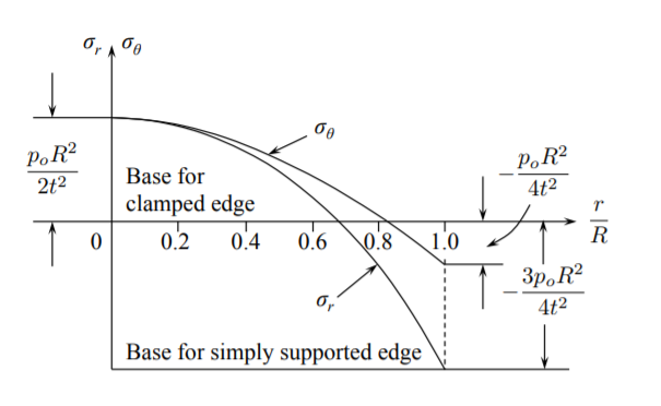
By comparing Equations \ref{7.32} and \ref{7.33}, it is seen that the maximum bending moment occurs at the edge \(r = R\). From the stress formula, Equation (3.7.7)
\[|\sigma_{rr}| = \left|\frac{M_rz}{h^3/12}\right|_{z=\frac{h}{2}} = p_o \frac{3}{4}\left(\frac{R}{h}\right)^2 \]
At the same time, the circumferential bending moment at \(r = R\) is
\[|\sigma_{\theta \theta}| = \frac{M_{\theta}z}{h^3/12} = p_o \frac{1}{4}\left(\frac{R}{h}\right)^2 \]